PPD-QCA62342x2 802.11a/b/g/n +BT module Module (SiP)
Qualcomm Atheros, Inc.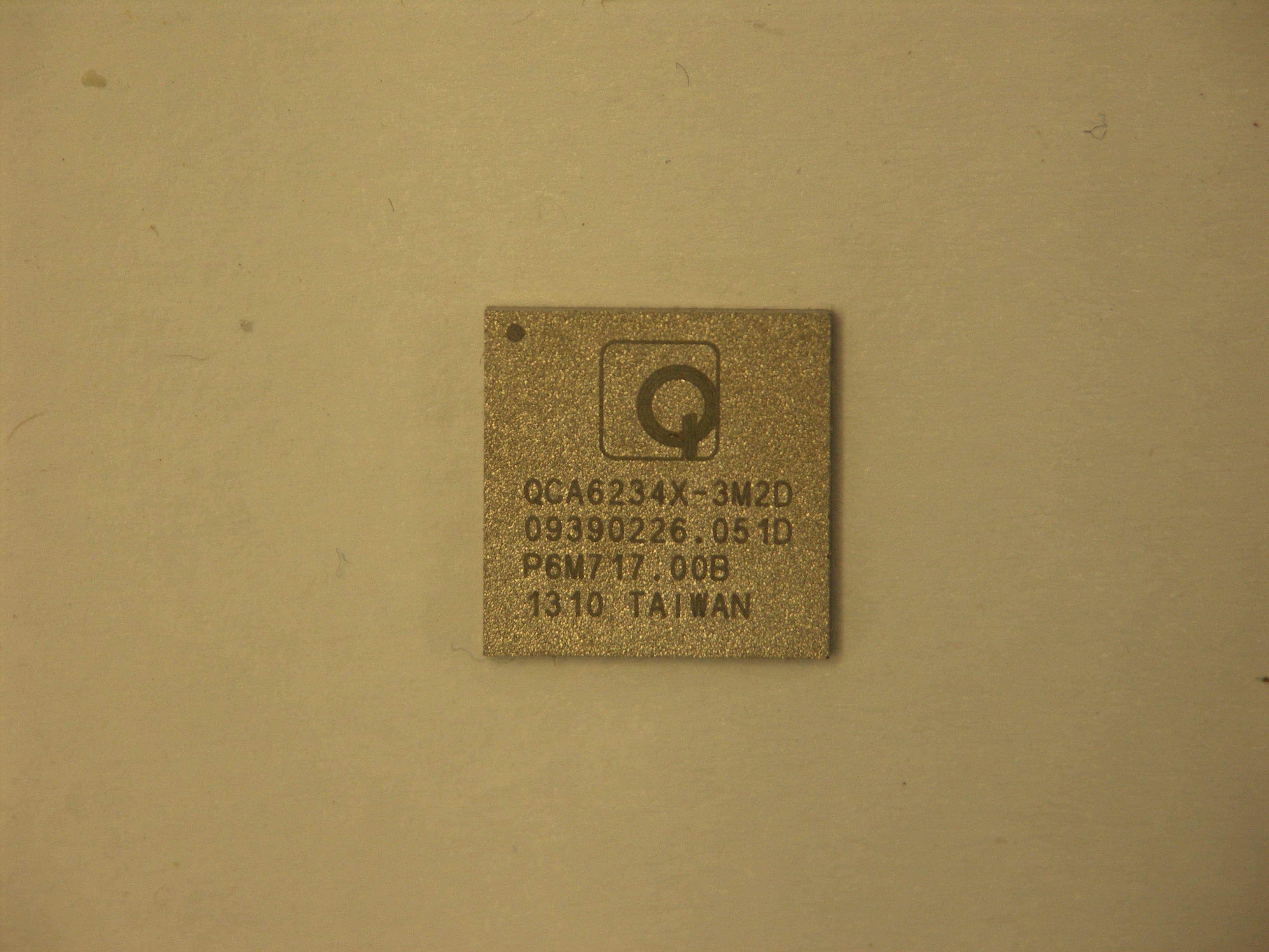
Click to zoom
Application Details
- Equipment Class
- DSS - Part 15 Spread Spectrum Transmitter
- Date of Grant
- Jul 11, 2013
- Application Purpose
- Original Equipment
- Date of Application
- Jul 11, 2013
- Equipment Note
- 2x2 802.11a/b/g/n +BT module Module (SiP)
- Frequency Range
- 2402.00000000 - 2480.00000000
- Company
- Qualcomm Atheros, Inc.
- Country
- United States
Documents & Files
Document Text
Text extracted from the exhibit documents filed with the FCC. Open a document above to read the original.
Users Manual
Confidential and Proprietary – Qualcomm Atheros, Inc. NO PUBLIC DISCLOSURE PERMITTED: Please report postings of this document on public servers or websites to: [email protected]. Restricted Distribution: Not to be distributed to anyone who is not an employee of either Qualcomm or its subsidiaries without the express approval of Qualcomm's Configuration Management. Not to be used, copied, reproduced, or modified in whole or in part, nor its contents revealed in any manner to others without the express written permission of Qualcomm Atheros, Inc. Qualcomm is a registered trademark of QUALCOMM Incorporated. Atheros is a registered trademark of Qualcomm Atheros, Inc. All other registered and unregistered trademarks are the property of QUALCOMM Incorporated, Qualcomm Atheros, Inc., or their respective owners and used with permission. Registered marks owned by QUALCOMM Incorporated and Qualcomm Atheros, Inc. are registered in the United States and may be registered in other countries. ARM is a registered trademark of ARM Limited. This technical data may be subject to U.S. and international export, re-export, or transfer (“export”) laws. Diversion contrary to U.S. and international law is strictly prohibited. Qualcomm Atheros, Inc. 1700 Technology Drive San Jose, CA 95110 U.S.A. © 2013 Qualcomm Atheros, Inc. QCA6234 Modular Certification OEM Integrator Instructions 80-xxxxx Rev. 1.4 July 12, 2013 80-xxxxx Rev. 1.4 MAY CONTAIN U.S. AND INTERNATIONAL EXPORT CONTROLLED INFORMATION 2 Confidential and Proprietary – Qualcomm Atheros, Inc. Revision history Revision Date Description Ver. 1.0 April 2013 Initial release Ver 1.1 June 2013 Ver 1.2 June 5, 2013 Updated FCC Labeling Ver 1.3 June 20, 2013 Updated System Level countries not done by QCA Ver 1.4 July 21, 2013 Typo/corrections per TCB review CAUTION: Qualcomm Atheros offers modular certifications (radio type approvals granted by global regulators) for the SiP product referenced in this document. The modular certifications may only be used by Qualcomm Atheros Partners/OEM Integrators who have signed the separately provided “Host Integrator Agreement”. Use of the modular certifications is subject to specific design and implementation restrictions and conditions as described in this document and the separately provided “SiP Module Certified Antennas and Layout” document. Any deviation from the provided instructions and agreements, including failure to take necessary action by the OEM Integrator could result in a violation of applicable national law and in such event, the modular certifications, and the host products into which the radio module is incorporated, may not be lawfully distributed or sold. Qualcomm Atheros assumes no responsibility for any liability or loss related to installation, integration, or operation of the Module. Per the Host Integrator agreement, Qualcomm Atheros reserves the right to review records and audit the Integrator’s adherence to the procedures and required actions stated in this document. 80-xxxxx Rev. 1.4 MAY CONTAIN U.S. AND INTERNATIONAL EXPORT CONTROLLED INFORMATION 3 Confidential and Proprietary – Qualcomm Atheros, Inc. Contents 1 Introduction ...................................................................................................... 4 2 Applicable Module ........................................................................................... 5 3 Available Global Modular Approvals ............................................................. 6 4 Deviation from Specifications for Host Layout, BOM, and Schematics ..... 7 5 Validation of SiP Radio Conformance as Implemented in Host .................. 8 6 Additional Regulatory Conformance Testing and/or Submissions Required by the Integrator ........................................................................... 9 7 Compliant/Allowable Tx Power Settings Programmed into EEPROM ...... 10 8 Allowable Antennas to Use with the SiP Module ........................................ 11 9 RF Safety of Each Host System Design....................................................... 13 10 Required Labeling on the Outside of the Host Device ............................. 15 10.1 FCC ........................................................................................................................... 15 10.2 Taiwan NCC ............................................................................................................. 15 10.3 European Community R&TTE ................................................................................. 16 11 Required Labeling on the Module .............................................................. 17 11.1 FCC labeling on the Module ..................................................................................... 17 11.2 Rest of world labeling on the Module ....................................................................... 17 11.3 Instructions to download the sample global label artwork with certification IDs .... 17 12 Required Regulatory Wording for User Guide/Installation Manual ......... 19 12.1 FCC compliance information .................................................................................... 19 12.2 Industry Canada notice ............................................................................................. 20 12.3 European Community (R&TTE) user manual wording and declaration .................. 22 12.4 European Community (R&TTE) Declaration of Conformity for System................. 23 12.5 Taiwan user manual wording .................................................................................... 24 12.6 Korea user manual wording ...................................................................................... 24 13 OEM Integrator Required Action Items ...................................................... 25 80-xxxxx Rev. 1.4 MAY CONTAIN U.S. AND INTERNATIONAL EXPORT CONTROLLED INFORMATION 4 Confidential and Proprietary – Qualcomm Atheros, Inc. 1 Introduction This documen…
Text truncated - open the document above for the full version.
Cover Letter(s)
QUALCOMM ATHEROS, INC. 1700 Technology Drive, San Jose, CA 95110 T 408.773.5200 | F 408- 773- 9940 qca.qualcomm.com Date:2013/6/3 Federal Communications Commission 7435 Oakland Mills Road Columbia MD 21046 Subject: Request for Confidentiality FCC ID: PPD -QCA6234 To Whom It May Concern: Pursuant to the provisions of Sections 0.457 and 0.459 of the Commission’s rules (47 CFR §§ 0.457, 0.459), we are requesting the Commission to withhold the following attachments as confidential document from public disclosure indefinitely. Schematic Diagram Block Diagram Theory of Operation and product data sheet Theory of Operation Addendum - Regulatory algorithms Certified Antennas and Layout document Above mentioned document contains detailed system and equipment description are considered as proprietary information in operation of the equipment. The public disclosure of above documents might be harmful to our company and would give competitor an unfair advantage in the market. Pursuant to DA 04-1705 of the Commission’s Rules, we request short-term confidential treatment for the following information until 180 days from date of Equipment Authorization in order to ensure sensitive business information remains confidential until the actual marketing of the device: External Photos Internal Photos Test Setup Photos Integrator Instructions It is our understanding that all measurement test reports, FCC ID label format and correspondent during certification review process cannot be granted as confidential documents and those information will be available for public review once the grant of equipment authorization is issued. Best Regards --------------------------------------------------------------------------- Michael Green / Manager, Global Product Compliance
Cover Letter(s)
Date: June 16, 2013 UL Verification Services Inc. Certification Division 47173 Benicia Street Fremont, CA 94538, USA To whom it may concern: I, the undersigned, hereby authorize UL Verification Services Inc. to act on our behalf in all manners relating to application for equipment authorization, including signing of all documents relating to these matters. Any and all acts carried out by UL Verification Services Inc. on our behalf shall have the same effect as acts of our own. I, the undersigned, hereby certify that we are not subject to a denial of federal benefits, that includes FCC benefits, pursuant to Section 5301 of the Anti-Drug Abuse Act of 1988, 21 U.S.C. 853(a). In authorizing UL Verification Services Inc. as our agent, we still recognize that we are responsible to: a) comply with the relevant provisions of the certification program; b) make all necessary arrangements for the conduct of the evaluation, including provision for examining documentation and access to all areas, records (including internal audit reports) and personnel for the purposes of evaluation (e.g. testing, inspection, assessment, surveillance, reassessment) and resolution of complaints; c) make claims regarding certification only in respect of the scope for which certification has been granted; d) do not use our product certification in such a manner as to bring the Certification Division into disrepute and not make any statement regarding our product certification which the Certification Division may consider misleading or unauthorized; e) upon suspension or cancellation of certification, discontinue use of all advertising matter that contains any reference thereto and return any certification documents as required by the Certification Division; f) use certification only to indicate the products are certified as being in conformity with specified standards; g) endeavor to ensure that no certificate or report nor any part thereof is used in a misleading manner; h) ensure that any reference to our product certification in communication media such as documents, brochures or advertising, complies with the requirements of the Certification Division; i) keep a record of all complaints made known to the us relating to the product’s compliance with requirements of the relevant standard and to make these records available to the Certification Division when requested; j) take appropriate action with respect to such complaints and any deficiencies found in products or services that affect compliance with the requirements for certification; k) document the actions taken. This authorization is valid until further written notice from the applicant. Sincerely Yours, Respectfully, Michael Green Manager, Global Product Compliance
Cover Letter(s)
Applicant/Grantee Qualcomm Atheros Inc. FCC ID: PPD- QCA6234 Section 15.212 Modular Transmitters Request for Modular Approval Request for Limited Modular Approval Requirements EUT Conditions Comply (Y/N) Single Modular Approval Requirements 1 The radio elements of the modular transmitter must have their own shielding. The physical crystal and tuning capacitors may be located external to the shielded radio elements. SiP package has a full Metallic coating. Y 2 The modular transmitter must have buffered modulation/data inputs (if such inputs are provided) to ensure that the module will comply with Part 15 requirements under conditions of excessive data rates or over-modulation. All inputs to the modules are buffered through logic or microprocessor inputs. Y 3 The modular transmitter must have its own power supply regulation. The transmitter has its own power supply regulator. Y 4 The modular transmitter must comply with the antenna and transmission system requirements of Sections 15.203, 15.204(b) and 15.204(c). The antenna must either be permanently attached or employ a “unique” antenna coupler (at all connections between the module and the antenna, including the cable). The “professional installation” provision of Section 15.203 is not applicable to modules but can apply to limited modular approvals under paragraph (b) of this section. Device complies with 15.203 & 15.204(c) via a permanent trace between SiP antenna output and the U.FL connector or integrated antenna. Y 5 The modular transmitter must be tested in a stand-alone configuration, i.e., the module must not be inside another device during testing for compliance with Part 15 requirements. Unless the transmitter module will be battery powered, it must comply with the AC line conducted requirements found in Section 15.207. AC or DC power lines and data input/output lines connected to the module must not contain ferrites, unless they will be marketed with the module (see Section 15.27(a)). The length of these lines shall be the length typical of actual use or, if that length is unknown, at least 10 centimeters to insure that there is no coupling between Device was tested outside the host for modular approval. Refer to setup photos. Y the case of the module and supporting equipment. Any accessories, peripherals, or support equipment connected to the module during testing shall be unmodi ed and commercially available (see Section 15.31(i)). 6 The modular transmitter must be equipped with either a permanently a xed label or must be capable of electronically displaying its FCC identi cation number. (A) If using a permanently a xed label, the modular transmitter must be labeled with its own FCC identi cation number, and, if the FCC identi cation number is not visible when the module is installed inside another device, then the outside of the device into which the module is installed must also display a label referring to the enclosed module. This exterior label can use wording such as the following: “Contains Transmitter Module FCC ID: XYZMODEL1” or “Contains FCC ID: XYZMODE L1.” Any similar wording that expresses the same meaning may be used. The Grantee may either provide such a label, an example of which must be included in the application for equipment authorization, or, must provide adequate instructions along with the module which explain this requirement. In the latter case, a copy of these instructions must be included in the application for equipment authorization. (B) If the modular transmitter uses an electronic display of the FCC identi cation number, the information must be readily accessible and visible on the modular transmitter or on the de vice in which it is installed. If the module is installed inside another device, then the outside of the device into which the module is installed must display a label referring to the enclosed module. This exterior label can use wording such as the following: “Contains FCC certi ed transmitter module(s).” Any similar wording that expresses the same meaning may be used. The user manual must include instructions on how to access the electronic display. A copy of these instructions must be included in the application for equipment authorization. 7 The modular transmitter must comply with requirements that ordinarily apply to a complete transmitter and the manufacturer must provide adequate instructions along with the module to explain any such requirements. A copy of these instructions must be included in the Refer to “Instuctions to OEM Integrators”. Y SiP package is too small to a x label or readable text with FCCID. End Integrators are instructed to label host device with the required text: Contains FCC ID: PPD-QCA6234 and to instruct where to nd the FCCID on the product. application for equipment authorization. 8 The modular transmitter must comply with any applicable RF exposure requirements in its final configuration. Transmitter meets RF Exposure requirements. of Refer to submitted test reports. . Y A limited modular approval may be granted for single or split modular transmitters that do not comply with all of the above requirements, e.g., shielding, minimum signaling amplitude, buffered modulation/data inputs, or power supply regulation, if the manufacturer can demonstrate by alternative means in the application for equipment authorization that the modular transmitter meets all the applicable Part 15 requirements under the operating conditions in which the transmitter will be used. Limited modular approval also may be granted in those instances where compliance with RF exposure rules is demonstrated only for particular product configurations. The applicant for certification must state how control of the end product into which the module will be installed will be maintained such that full compliance of the end product is always ensured.
ID Label/Location Info
Per KDB Tracking Number 436863: The FCC ID label will be placed in the User's Manual and on the outside of the host product as shown below
RF Exposure Info
FCC Part 1 Subpart I FCC Part 2 Subpart J INDUSTRY CANADA RSS 102 ISSUE 3 RF EXPOSURE REPORT FOR 2x2 802.11a/b/g/n +BT Module (SiP) MODEL NUMBER: QCA6234 FCC ID: PPD-QCA6234 IC: 4104A-QCA6234 REPORT NUMBER: 13U14995-10 ISSUE DATE: JULY 2, 2013 Prepared for QUALCOMM ATHEROS, INC. 1700 TECHNOLOGY DRIVE SAN JOSE, CA 95110 Prepared by UL VERIFICATION SERVICES INC. 47173 BENICIA STREET FREMONT, CA 94538, U.S.A. TEL: (510) 771-1000 FAX: (510) 661-0888 REPORT NO: 13U14995-10 DATE: JULY 02, 2013 FCC ID: PPD-QCA6234 IC: 4104A-QCA6234 Page 2 of 11 UL VERIFICATION SERVICES INC. FORM NO: CCSUP4701I 47173 BENICIA STREET, FREMONT, CA 94538, USA TEL: (510) 771-1000 FAX: (510) 661-0888 This report shall not be reproduced except in full, without the written approval of . UL Verification Services Inc. Revision History Rev. Issue Date Revisions Revised By -- 07/02/13 Initial Issue F. Ibrahim REPORT NO: 13U14995-10 DATE: JULY 02, 2013 FCC ID: PPD-QCA6234 IC: 4104A-QCA6234 Page 3 of 11 UL VERIFICATION SERVICES INC. FORM NO: CCSUP4701I 47173 BENICIA STREET, FREMONT, CA 94538, USA TEL: (510) 771-1000 FAX: (510) 661-0888 This report shall not be reproduced except in full, without the written approval of . UL Verification Services Inc. TABLE OF CONTENTS 1. ATTESTATION OF TEST RESULTS ................................................................................. 4 2. TEST METHODOLOGY ..................................................................................................... 5 3. REFERENCES ................................................................................................................... 5 4. FACILITIES AND ACCREDITATION ................................................................................. 5 5. MAXIMUM PERMISSIBLE RF EXPOSURE ....................................................................... 6 5.1. FCC RULES ................................................................................................................ 6 5.2. IC RULES .................................................................................................................... 7 5.3. EQUATIONS ................................................................................................................ 8 5.4. LIMITS AND IC EXEMPTION .....................................................................................10 6. RF EXPOSURE RESULTS ................................................................................................11 REPORT NO: 13U14995-10 DATE: JULY 02, 2013 FCC ID: PPD-QCA6234 IC: 4104A-QCA6234 Page 4 of 11 UL VERIFICATION SERVICES INC. FORM NO: CCSUP4701I 47173 BENICIA STREET, FREMONT, CA 94538, USA TEL: (510) 771-1000 FAX: (510) 661-0888 This report shall not be reproduced except in full, without the written approval of . UL Verification Services Inc. 1. ATTESTATION OF TEST RESULTS COMPANY NAME: QUALCOMM ATHEROS, INC 1700 TECHNOLOGY DRIVE SAN JOSE, CA 95100 EUT DESCRIPTION: 2x2 802.11a/b/g/n +BT Module (SiP) MODEL: QCA6234 SERIAL NUMBER: 75720088, 75720080 DATE TESTED: April 19 - May 24, 2013 APPLICABLE STANDARDS STANDARD TEST RESULTS FCC PART 1 SUBPART I & PART 2 SUBPART J Pass INDUSTRY CANADA RSS 102 ISSUE 3 Pass UL Verification Services Inc. calculated the RF Exposure of the above equipment in accordance with the requirements set forth in the above standards, using test results reported in the test report documents referenced below and/or documentation furnished by the applicant. All indications of Pass/Fail in this report are opinions expressed by UL Verification Services Inc. based on interpretations of these calculations. The results show that the equipment is capable of demonstrating compliance with the requirements as documented in this report. Note: The results documented in this report apply only to the tested sample, under the conditions and modes of operation as described herein. This document may not be altered or revised in any way unless done so by UL Verification Services Inc. and all revisions are duly noted in the revisions section. Any alteration of this document not carried out by UL Verification Services Inc. will constitute fraud and shall nullify the document. This report must not be used by the client to claim product certification, approval, or endorsement by NVLAP, NIST, any agency of the Federal Government, or any agency of any government. Approved & Released For UL Verification Services Inc. By: Calculated By: FRANK IBRAHIM DAVID GARCIA WiSE PROGRAM MANAGER EMC ENGINEER UL Vérification Services Inc. UL Vérification Services Inc. REPORT NO: 13U14995-10 DATE: JULY 02, 2013 FCC ID: PPD-QCA6234 IC: 4104A-QCA6234 Page 5 of 11 UL VERIFICATION SERVICES INC. FORM NO: CCSUP4701I 47173 BENICIA STREET, FREMONT, CA 94538, USA TEL: (510) 771-1000 FAX: (510) 661-0888 This report shall not be reproduced except in full, without the written approval of . UL Verification Services Inc. 2. TEST METHODOLOGY All calculations were made in accordance with FCC OET Bulletin 65 Edition 97-01 and IC Safety Code 6. 3. REFERENCES All measurements were made as documented in test report UL Verification Services Inc. Document 13U14995-1 for operation in the 2.4 GHz band and UL Verification Services Inc. Document 13U14995-2 for operation in the 5 GHz bands. Output power, Duty cycle and Antenna gain data is excerpted from the applicable test reports. Antenna gain data is excerpted from the applicable test reports. 4. FACILITIES AND ACCREDITATION The test sites and measurement facilities used to collect data are located at 47173 Benicia Street, Fremont, California, USA. UL Verification Services Inc. is accredited by NVLAP, Laboratory Code 200065-0. The full scope of accreditation can be viewed at http://www.ccsemc.com. REPORT NO: 13U14995-10 DATE: JULY 02, 2013 FCC ID: PPD-QCA6234 IC: 4104A-QCA6234 Page 6 of 11 UL VERIFICATION SERVICES INC. FORM NO: CCSUP4701I 47173 BENICIA STREET, FREMONT, CA 94538, USA TEL: (510) 771-1000 FAX: (510) 661-0888 This report shall not be reprodu…
Text truncated - open the document above for the full version.
Test Report
FCC 47 CFR PART 15 SUBPART C INDUSTRY CANADA RSS-210 ISSUE 8 CERTIFICATION TEST REPORT FOR 2x2 802.11a/b/g/n +BT Module (SiP) MODEL NUMBER: QCA6234 FCC ID: PPD-QCA6234 IC: 4104A-QCA6234 REPORT NUMBER: 13U14995-3, Revision A ISSUE DATE: JULY 1, 2013 Prepared for QUALCOMM ATHEROS, INC. 1700 TECHNOLOGY DRIVE SAN JOSE, CA 95100 Prepared by UL VERIFICATION SERVICES INC. 47173 BENICIA STREET FREMONT, CA 94538, U.S.A. TEL: (510) 771-1000 FAX: (510) 661-0888 REPORT NO: 13U14995-3A DATE: JULY 1, 2013 FCC ID: PPD-QCA6234 IC: 4104A-QCA6234 Page 2 of 110 UL VERIFICATION SERVICES INC. FORM NO: CCSUP4701I 47173 BENICIA STREET, FREMONT, CA 94538, USA TEL: (510) 771-1000 FAX: (510) 661-0888 This report shall not be reproduced except in full, without the written approval of UL Verification Services Inc. Revision History Rev. Issue Date Revisions Revised By -- 06/28/13 Initial Issue F. Ibrahim A 07/01/13 Corrected EUT Description AAumentado REPORT NO: 13U14995-3A DATE: JULY 1, 2013 FCC ID: PPD-QCA6234 IC: 4104A-QCA6234 Page 3 of 110 UL VERIFICATION SERVICES INC. FORM NO: CCSUP4701I 47173 BENICIA STREET, FREMONT, CA 94538, USA TEL: (510) 771-1000 FAX: (510) 661-0888 This report shall not be reproduced except in full, without the written approval of UL Verification Services Inc. TABLE OF CONTENTS 1. ATTESTATION OF TEST RESULTS ................................................................................. 5 2. TEST METHODOLOGY ..................................................................................................... 6 3. FACILITIES AND ACCREDITATION ................................................................................. 6 4. CALIBRATION AND UNCERTAINTY ................................................................................ 6 4.1. MEASURING INSTRUMENT CALIBRATION .............................................................. 6 4.2. SAMPLE CALCULATION ............................................................................................ 6 4.3. MEASUREMENT UNCERTAINTY ............................................................................... 6 5. EQUIPMENT UNDER TEST ............................................................................................... 7 5.1. DESCRIPTION OF EUT .............................................................................................. 7 5.2. MAXIMUM OUTPUT POWER...................................................................................... 7 5.3. DESCRIPTION OF AVAILABLE ANTENNAS .............................................................. 7 5.4. SOFTWARE AND FIRMWARE .................................................................................... 7 5.5. WORST-CASE CONFIGURATION AND MODE .......................................................... 7 5.6. DESCRIPTION OF TEST SETUP ................................................................................ 8 6. TEST AND MEASUREMENT EQUIPMENT ......................................................................10 7. ON TIME AND DUTY CYCLE ............................................................................................11 7.1. ON TIME AND DUTY CYCLE RESULTS ....................................................................11 7.2. DUTY CYCLE PLOTS ................................................................................................12 8. ANTENNA PORT TEST RESULTS ...................................................................................13 8.1. BASIC DATA RATE GFSK MODULATION .................................................................13 8.1.1. 20 dB AND 99% BANDWIDTH ............................................................................13 8.1.2. HOPPING FREQUENCY SEPARATION .............................................................17 8.1.3. NUMBER OF HOPPING CHANNELS ..................................................................19 8.1.4. AVERAGE TIME OF OCCUPANCY ....................................................................22 8.1.5. OUTPUT POWER ...............................................................................................27 8.1.6. AVERAGE POWER .............................................................................................30 8.1.7. CONDUCTED SPURIOUS EMISSIONS ..............................................................31 8.2. ENHANCED DATA RATE QPSK MODULATION........................................................36 8.2.1. AVERAGE TIME OF OCCUPANCY ....................................................................36 8.2.2. OUTPUT POWER ...............................................................................................40 8.2.3. AVERAGE POWER .............................................................................................43 8.3. ENHANCED DATA RATE 8PSK MODULATION ........................................................44 8.3.1. 20 dB AND 99% BANDWIDTH ............................................................................44 8.3.2. HOPPING FREQUENCY SEPARATION .............................................................48 8.3.3. NUMBER OF HOPPING CHANNELS ..................................................................50 8.3.4. AVERAGE TIME OF OCCUPANCY ....................................................................53 8.3.5. OUTPUT POWER ...............................................................................................57 REPORT NO: 13U14995-3A DATE: JULY 1, 2013 FCC ID: PPD-QCA6234 IC: 4104A-QCA6234 Page 4 of 110 UL VERIFICATION SERVICES INC. FORM NO: CCSUP4701I 47173 BENICIA STREET, FREMONT, CA 94538, USA TEL: (510) 771-1000 FAX: (510) 661-0888 This report shall not be reproduced except in full, without the written approval of UL Verification Services Inc. 8.3.6. AVERAGE POWER .............................................................................................60 8.3.7. CONDUCTED SPURIOUS EMISSIONS ..............................................................61 9. RADIATED TEST RESULTS .........................…
Text truncated - open the document above for the full version.
Test Setup Photos
REPORT NO: 13U14995-3A DATE: JULY 1, 2013 FCC ID: PPD-QCA6234 IC: 4104A-QCA6234 Page 103 of 110 UL VERIFICATION SERVICES INC. FORM NO: CCSUP4701I 47173 BENICIA STREET, FREMONT, CA 94538, USA TEL: (510) 771-1000 FAX: (510) 661-0888 This report shall not be reproduced except in full, without the written approval of UL Verification Services Inc. 11. SETUP PHOTOS ANTENNA PORT CONDUCTED RF MEASUREMENT SETUP ANTENNA PORT CONDUCTED PHOTO REPORT NO: 13U14995-3A DATE: JULY 1, 2013 FCC ID: PPD-QCA6234 IC: 4104A-QCA6234 Page 104 of 110 UL VERIFICATION SERVICES INC. FORM NO: CCSUP4701I 47173 BENICIA STREET, FREMONT, CA 94538, USA TEL: (510) 771-1000 FAX: (510) 661-0888 This report shall not be reproduced except in full, without the written approval of UL Verification Services Inc. RADIATED RF MEASUREMENT SETUP (BELOW 1 GHz) RADIATED FRONT PHOTO (BELOW 1 GHz) RADIATED BACK PHOTO (BELOW 1 GHz) REPORT NO: 13U14995-3A DATE: JULY 1, 2013 FCC ID: PPD-QCA6234 IC: 4104A-QCA6234 Page 105 of 110 UL VERIFICATION SERVICES INC. FORM NO: CCSUP4701I 47173 BENICIA STREET, FREMONT, CA 94538, USA TEL: (510) 771-1000 FAX: (510) 661-0888 This report shall not be reproduced except in full, without the written approval of UL Verification Services Inc. RADIATED RF MEASUREMENT SETUP (ABOVE 1 GHz) RADIATED FRONT PHOTO (ABOVE 1 GHz) RADIATED BACK PHOTO (ABOVE 1 GHz) REPORT NO: 13U14995-3A DATE: JULY 1, 2013 FCC ID: PPD-QCA6234 IC: 4104A-QCA6234 Page 106 of 110 UL VERIFICATION SERVICES INC. FORM NO: CCSUP4701I…
Text truncated - open the document above for the full version.
Contact Information
Applicant
Paul Guckian(Vice President, Regulatory Engineering)
Technical Contact
UL VERIFICATION SERVICES INC.ANA AUMENTADO
[email protected],[email protected]510.771.1087
47173 BENICIA ST · FREMONT, California
Non-Technical Contact
UL VERIFICATION SERVICES INC.ANA AUMENTADO
[email protected]510.771.1087
Test Firm
Compliance Certification ServicesThu Chan
Technical Specifications
| # | Rule Parts | Frequency Range | Power Output |
|---|---|---|---|
| 1 | 15C | 2.40 GHz - 2.48 GHz | 13.03 mW |
Other Applications from Qualcomm Atheros, Inc.
PPD-QCNFA425
Sep 01, 2015Single Stream 802.11a/b/g/n/ac + BT 4.1 M.2 1216 Type Card
Equipment Class
DTS - Digital Transmission System
PPD-QCA9008-SBD1
Aug 18, 2015802.11ad MODULE
Equipment Class
DXT - Part 15 Low Power Transceiver, Rx Verified
PPD-QCNFA344AH
May 27, 2015802.11a/b/g/n/ac + BT 4.1 M.2 2230 Type Card
Equipment Class
JBP - Part 15 Class B Computing Device Peripheral
PPD-QCNFA364AH
May 27, 2015802.11a/b/g/n/ac + BT 4.1 M.2 2230 Type Card
Equipment Class
DTS - Digital Transmission System
PPD-QCNFA344A
Apr 30, 2015802.11a/b/g/n/ac + BT 4.1 M.2 2230 Type Card
Equipment Class
NII - Unlicensed National Information Infrastructure TX