PPD-QCWB342Dual Band 2x2 MIMO 802.11ac/abgn WLAN plus BT
Qualcomm Atheros, Inc.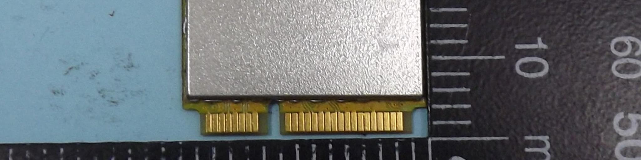
Click to zoom
Application Details
- Equipment Class
- DTS - Digital Transmission System
- Date of Grant
- Jul 21, 2013
- Application Purpose
- Original Equipment
- Date of Application
- Jul 21, 2013
- Equipment Note
- Dual Band 2x2 MIMO 802.11ac/abgn WLAN plus BT
- Frequency Range
- 5745.00000000 - 5825.00000000
- Company
- Qualcomm Atheros, Inc.
- Country
- United States
Documents & Files
Document Text
Text extracted from the exhibit documents filed with the FCC. Open a document above to read the original.
Users Manual
Confidential and Proprietary - Qualcomm Atheros, Inc. Not to be used, copied, reproduced in whole or in part, nor its contents revealed in any manner to others without the express written permission of Qualcomm Atheros, Inc. QUALCOMM is registered trademark of Qualcomm Incorporated. ATHEROS is a registered trademark of Qualcomm Atheros, Inc. Any other registered and unregistered trademarks are the property of Qualcomm Incorporated, Qualcomm Atheros, Inc. or their respective owners and used with permission. Registered marks owned by Qualcomm Incorporated and Qualcomm Atheros, Inc. are registered in the United States of America and may be registered in other countries. This technical data may be subject to U.S. and international export, re-export, or transfer (“export”) laws. Diversion contrary to U.S. and international law is strictly prohibited. Qualcomm Atheros, Inc. 1700 Technology Drive San Jose, CA 95110-1383 U.S.A. Copyright © 2011 Qualcomm Atheros, Inc. All rights reserved. WB342 Modular Certification OEM Integrator Instructions MKG-17218 Ver. 1.4 July 17, 2013 MKG-17218 Ver. 1.4 2 Confidential and Proprietary - Qualcomm Atheros, Inc. MAY CONTAIN U.S. AND INTERNATIONAL EXPORT CONTROLLED INFORMATION Revision history Revision Date Description Ver. 1.1 May 2013 Initial release Ver. 1.2 June 2013 Revision content to Section 8 Ver. 1.3 July 2013 Revision for some sentence Ver. 1.4 July 2013 Change antenna separation distance to 5 cm NOTE: The Qualcomm Atheros (QCA) design radio module (the “Module”) is designed for use only in specific countries in which QCA has obtained certificates of compliance with local laws and regulations. Therefore, the Module may not be sold, operated or incorporated into products for use in countries for which it has not been certified. See Section 3 herein. In addition, any deviation from the settings, methods, conditions and restrictions for integration of the Module into a host system, as detailed in this document, could be a violation of applicable national law and may be punishable as such, and in such event, the products into which the Module is incorporated may not be lawfully distributed or sold in such countries. QCA assumes no responsibility for any liability or loss related to installation, integration or operation of the Module. WB342 Modular Certification OEM Integrator Instructions MKG-17218 Ver. 1.4 3 Confidential and Proprietary - Qualcomm Atheros, Inc. MAY CONTAIN U.S. AND INTERNATIONAL EXPORT CONTROLLED INFORMATION Contents 1 Introduction ...................................................................................................... 4 2 Applicable Module ........................................................................................... 4 3 Available Global Modular Approvals from Qualcomm Atheros .................. 5 4 Additional Regulatory Conformance Testing and/or Submissions Required by the Integrator ........................................................................... 5 5 Compliant/Allowable Tx Power Settings Programmed into EEPROM ........ 7 6 Allowable Antennas For Use With The Radio Module .................................. 7 7 Antenna Placement inside the Host System and RF Safety ........................ 8 8 Simultaneous Transmission with Other Integrated or Plug-In Radios ....... 8 9 Module May Not Be Installed by End Users .................................................. 9 10 Required Labeling on the Outside of the Host .......................................... 10 10.1 FCC ........................................................................................................................... 10 10.2 Taiwan NCC ............................................................................................................. 10 10.3 European Community R&TTE ................................................................................. 11 11 Required Labeling on the Module .............................................................. 12 11.1 FCC labeling on the Module ..................................................................................... 12 11.2 Rest of world labeling on the Module ....................................................................... 12 11.3 Instructions to download the sample global label artwork with certification IDs .... 12 12 Required Regulatory Wording for User Manual/Installation Manual ....... 13 12.1 FCC compliance information .................................................................................... 13 12.2 Industry Canada notice ............................................................................................. 14 12.3 European Community (R&TTE) user manual wording and declaration .................. 15 12.4 European Community (R&TTE) Declaration of Conformity for System................. 17 12.5 Taiwan user manual wording .................................................................................... 17 12.6 Korea user manual wording ...................................................................................... 18 13 OEM Integrator Checklist ............................................................................ 19 WB342 Modular Certification OEM Integrator Instructions MKG-17218 Ver. 1.4 4 Confidential and Proprietary - Qualcomm Atheros, Inc. MAY CONTAIN U.S. AND INTERNATIONAL EXPORT CONTROLLED INFORMATION 1 Introduction This document describes the steps that the OEM integrator must follow when designing and manufacturing a system utilizing a Qualcomm Atheros (QCA) design radio module (the “Module”). Failure to follow the instructions in this document may invalidate the FCC certification and authorization of the Module for use in the U.S. and in other countries. The Qualcomm Atheros modular certifications described in this document apply only to radio conformance for the Module. The OEM integrator is responsible for all system-level EMI/EMC and Product Safety testing and certification that apply to the host system in the U.S.…
Text truncated - open the document above for the full version.
Cover Letter(s)
QUALCOMM ATHEROS, INC. 1700 Technology Drive, San Jose, CA 95110 T 408.773.5200 | F 408-773-9940 qca.qualcomm.com Power of Attorney 2013/5/27 To whom it may concern: We, the undersigned Qualcomm Atheros, Inc. hereby authorize Sporton International Inc. to act on our behalf in all matters relating to all processes required in the FCC Part 15 approval and any communication needed with the national authority. Any and all acts carried out by Sporton Internal Inc. on our behalf shall have the same effects as acts of our own. This authorization is limited to the following products: FCC ID: PPD-QCWB342 We further certifies that neither the applicant nor any party to this application, as defined in 47 CFR Ch. 1.2002 (b), is subject to a denial to Federal benefits, that include FCC benefits, pursuant to section 5301 of the Anti-Drug Abuse Act of 1998, 21 U.S.C. 835(a). If you have any questions regarding the authorization, please don’t hesitate to contact us. Thank you! Sincerely yours, --------------------------------------------------------------------------- Michael Green / Manager, Global Product Compliance
Cover Letter(s)
J QUALCOMM Incorporated 5775 Morehouse Drive San Diego, CA 92121-1714 www.qualcomm.com June 15, 2011 Federal Communications Commission 7435 Oakland Mills Road Columbia MD 21046 Subject: Authorization of Handling FCC Regulatory Applications To Whom It May Concern: I, hereby, authorize Mr. Michael Green, to handle FCC Regulatory related applications for QUALCOMM ATHEROS Incorporated and sign all required application documents. Best Regards, Paul Guckian VP, Engineering QUALCOMM Incorporated 5775 Morehouse Drive San Diego, CA 92121 Office: 858-651-1547 [email protected]
Cover Letter(s)
Date: May 31th 2013 Federal Communications Commission Authorization and Evaluation Division 7435 Oakland Mills Road Columbia, MD 21046 Attn: OET Dept. Ref: Modular Approval request letter FCC ID: PPD-QCWB342 Applicant: Qualcomm Atheros, Inc. Dear Examiner, The requirements regulated in 15.212 have been fulfilled and clearly explained below. 1. The requirement of RF shielding: The shielding of the radio portion can be demonstrated in exhibition External Photo. 2. The requirement of buffered inputs: Buffered data inputs stage has been integrated in chip QCA9862. 3. The requirement of power supply regulation: The part number of the power regulator is QCA9862. 4. The requirements of section 15.203 and 15.204(C): The requirements of antenna connector and spurious emission have been fulfilled. Please reference the exhibition Test Report. 5. The requirement of stand-alone test configuration: Please reference exhibition Test Configuration Photo for the stand-alone test configuration. 6. The requirement of labeling: The instruction on the labeling rule of the end product has been stated in the users manual of this module. Please also see the exhibition Label Sample. 7. The requirement of compliance on specific rule or operating requirements: The required FCC rule has been fulfilled and all the instructions for maintaining compliance has been clearly stated in the Users Manual. 8. The requirement of RF exposure: Please refer exhibition RF Exposure for the compliance of SAR RF exposure rule. Please do not hesitate to contact me for any questions of this request letter. Sincerely yours, Michael Green Manager, Global Product Compliance Qualcomm Atheros, Inc.
Cover Letter(s)
QUALCOMM ATHEROS, INC. 1700 Technology Drive, San Jose, CA 95110 T 408.773.5200 | F 408-773-9940 qca.qualcomm.com Date:2013/6/17 Federal Communications Commission 7435 Oakland Mills Road Columbia MD 21046 Subject: Request for Confidentiality FCC ID: PPD-QCWB342 To Whom It May Concern: Pursuant to the provisions of Sections 0.457 and 0.459 of the Commission’s rules (47 CFR §§ 0.457, 0.459), we are requesting the Commission to withhold the following attachments as confidential document from public disclosure indefinitely. Schematic Diagram Block Diagram Theory of Operation Theory of Operation Addendum - Regulatory algorithms Above mentioned document contains detailed system and equipment description are considered as proprietary information in operation of the equipment. The public disclosure of above documents might be harmful to our company and would give competitor an unfair advantage in the market. Pursuant to DA 04-1705 of the Commission’s Rules, we request short-term confidential treatment for the following information to 180 days of Equipment Authorization in order to ensure sensitive business information remains confidential until the actual marketing of the device: External Photos Internal Photos Test Setup Photos User Manual WB342 Integrator Instructions It is our understanding that all measurement test reports, FCC ID label format and correspondent during certification review process cannot be granted as confidential documents and those information will be available for public review once the grant of equipment authorization is issued. Best Regards --------------------------------------------------------------------------- Michael Green / Manager, Global Product Compliance
External Photos
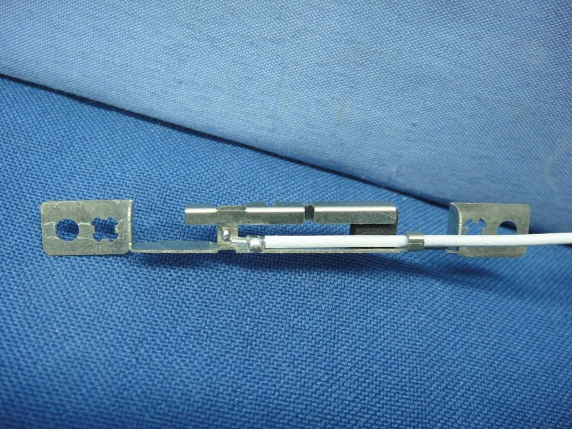
FCC / IC Radio Test Report Report No. : EP322814 SPORTON International Inc. PAGE NUMBER : B1 OF B4 TEL : 886-3-327-3456 ISSUED DATE : Jun. 17, 2013 FAX : 886-3-327-0973 APPENDIX B. Photographs of EUT FCC / IC Radio Test Report Report No. : EP322814 SPORTON International Inc. PAGE NUMBER : B3 OF B4 TEL : 886-3-327-3456 ISSUED DATE : Jun. 17, 2013 FAX : 886-3-327-0973 AUX Antenna FCC / IC Radio Test Report Report No. : EP322814 SPORTON International Inc. PAGE NUMBER : B4 OF B4 TEL : 886-3-327-3456 ISSUED DATE : Jun. 17, 2013 FAX : 886-3-327-0973 Main Antenna
ID Label/Location Info
PROPOSED FCC ID LABEL AND LOCATION Printed Color: Black 地色:White 材質:一般合成紙 粘著材:樹脂系糊 Top of EUT shielding FCC / IC Label Location QUALCOMM ATHEROS, INC. This device complies with Part 15 of the FCC Rules. Operation is subject to the following two conditions: (1) this device may not cause harmful interference, and (2) this device must accept any interference received, including interference that may cause undesired operation. FCC ID: PPD-QCWB342 IC: 4104A-QCWB342 Model: QCWB342
Internal Photos
FCC / IC Radio Test Report Report No. : EP322814 SPORTON International Inc. PAGE NUMBER : B1 OF B4 TEL : 886-3-327-3456 ISSUED DATE : Jun. 17, 2013 FAX : 886-3-327-0973 APPENDIX B. Photographs of EUT FCC / IC Radio Test Report Report No. : EP322814 SPORTON International Inc. PAGE NUMBER : B2 OF B4 TEL : 886-3-327-3456 ISSUED DATE : Jun. 17, 2013 FAX : 886-3-327-0973 FCC / IC Radio Test Report Report No. : EP322814 SPORTON International Inc. PAGE NUMBER : B3 OF B4 TEL : 886-3-327-3456 ISSUED DATE : Jun. 17, 2013 FAX : 886-3-327-0973 AUX Antenna FCC / IC Radio Test Report Report No. : EP322814 SPORTON International Inc. PAGE NUMBER : B4 OF B4 TEL : 886-3-327-3456 ISSUED DATE : Jun. 17, 2013 FAX : 886-3-327-0973 Main Antenna
RF Exposure Info
FCC OET BULLETIN 65 SUPPLEMENT C 01-01 IEEE Std 1528-2003 and IEEE Std 1528a-2005 SAR EVALUATION REPORT For QCWB342: 2X2 MIMO 802.11a/b/g/n/ac +BT Module Model: QCWB342 FCC ID: PPD-QCWB342 Report Number: 13U14858-1B Issue Date: 7/15/2013 Prepared for Qualcomm Atheros, Inc. 1700 Technology Dr. San Jose, CA 95110 Prepared by UL Verification Services Inc. 47173 BENICIA STREET FREMONT, CA 94538, U.S.A. TEL: (510) 771-1000 FAX: (510) 661-0888 Report No.: 13U14993-1B Issue Date: 7/15/2013 FCC ID: PPD-QCWB342 Page 2 of 37 UL VERIFICATION SERVICES INC. FORM NO: CCSUP4031G 47173 BENICIA STREET, FREMONT, CA 94538, USA TEL: (510) 771-1000 FAX: (510) 661-0888 This report shall not be reproduced except in full, without the written approval of UL Verification Services Inc. Revision History Rev. Issue Date Revisions Revised By -- 6/7/2013 Initial Issue -- A 7/5/2013 Section 9.2 – Deleted unauthorized 5GHz test frequencies. Section 12.2 – Added SAR result for channel 136 (replacing result for channel 124) Section 11 – Updated Liquid and system check data. Dave Weaver B 7/15/2013 Section 7.3 – Expanded test rationale for clarity. Dave Weaver Section 8 – Removed reference to non-existent section and added explanation of test separation distance. Section 4 – Corrected power sensor calibration date. Report No.: 13U14993-1B Issue Date: 7/15/2013 FCC ID: PPD-QCWB342 Page 3 of 37 UL VERIFICATION SERVICES INC. FORM NO: CCSUP4031G 47173 BENICIA STREET, FREMONT, CA 94538, USA TEL: (510) 771-1000 FAX: (510) 661-0888 This report shall not be reproduced except in full, without the written approval of UL Verification Services Inc. Table of Contents 1. Attestation of Test Results ............................................................................................................. 5 2. Test Methodology ........................................................................................................................... 6 3. Facilities and Accreditation ........................................................................................................... 6 4. Calibration and Uncertainty ........................................................................................................... 7 4.1. Measuring Instrument Calibration .............................................................................................. 7 4.2. Measurement Uncertainty .......................................................................................................... 8 5. Measurement System Description and Setup ............................................................................... 9 6. SAR Measurement Procedure ...................................................................................................... 10 6.1. Normal SAR Measurement Procedure ..................................................................................... 10 6.2. Volume Scan Procedures ........................................................................................................ 12 7. Device Under Test ......................................................................................................................... 13 7.1. General Information ................................................................................................................. 13 7.2. Band and Air Interfaces ........................................................................................................... 13 7.3. Testing Rationale ..................................................................................................................... 13 8. RF Exposure Conditions .............................................................................................................. 14 8.1. Body ........................................................................................................................................ 14 9. RF Output Power Measurement ................................................................................................... 15 9.1. WiFi (2.4 GHz Band) ................................................................................................................ 15 9.2. WiFi (5 GHz Bands) ................................................................................................................. 16 9.3. Bluetooth ................................................................................................................................. 19 10. Tissue Dielectric Properties ..................................................................................................... 20 10.1. Composition of Ingredients for the Tissue Material Used in the SAR Tests .......................... 21 10.2. Tissue Dielectric Parameter Check Results .......................................................................... 22 11. System Performance Check ..................................................................................................... 23 11.1. System Performance Check Measurement Conditions ......................................................... 23 11.2. Reference SAR Values for System Performance Check....................................................... 23 11.3. System Performance Check Results .................................................................................... 24 12. SAR Test Results ...................................................................................................................... 25 12.1. Wi-Fi (2.4 GHz Band) ........................................................................................................... 25 12.2. Wi-Fi (5 GHz Bands) ............................................................................................................ 26 12.3. Enhanced Energy Coupling .................................................................................................. 29 Report No.: 13U14993-1B Issue Date: 7/15/2013 FCC ID: PPD-QCWB342 Page 4 of 37 UL VERIFICATION SERVICES INC. FORM NO: CCSUP4031G 47173 BENICIA …
Text truncated - open the document above for the full version.
RF Exposure Info
Plot No. 1 Test Laboratory: UL CCS SAR Lab 1 Date: 5/15/2013 WiFi2.4GHz Frequency: 2437 MHz; Duty Cycle: 1:1; Room Ambient Temperature: 24.0C; Liquid Temperature: 23.0C Medium parameters used (interpolated): f = 2437 MHz; σ = 1.848 S/m; ε r = 50.753; ρ = 1000 kg/m 3 DASY5 Configuration: - Area Scan Setting: Find Secondary Maximum Within: 2.0 dB and with a peak SAR value greater than 0.0012W/kg - Electronics: DAE4 Sn1259; Calibrated: 2/7/2013 - Probe: EX3DV3 - SN3531; ConvF(7.54, 7.54, 7.54); Calibrated: 11/15/2012; - Sensor-Surface: 2.5mm (Mechanical Surface Detection) - Phantom: ELI-A v5.0; Type: QDOVA002AA; Serial: TP 1194 Horizontal Right/802.11b_ch 6 2.4GHz @ 9.5mm/Area Scan (9x9x1): Measurement grid: dx=12mm, dy=12mm Info: Interpolated medium parameters used for SAR evaluation. Maximum value of SAR (measured) = 0.823 W/kg Horizontal Right/802.11b_ch 6 2.4GHz @ 9.5mm/Zoom Scan (7x7x7)/Cube 0: Measurement grid: dx=5mm, dy=5mm, dz=5mm Reference Value = 21.111 V/m; Power Drift = -0.07 dB Peak SAR (extrapolated) = 1.46 W/kg SAR(1 g) = 0.753 W/kg; SAR(10 g) = 0.364 W/kg Info: Interpolated medium parameters used for SAR evaluation. Maximum value of SAR (measured) = 1.04 W/kg 0 dB = 1.04 W/kg = 0.17 dBW/kg Plot No. 2 Test Laboratory: UL CCS SAR Lab 1 Date: 5/20/2013 WiFi 5GHz Frequency: 5620 MHz; Duty Cycle: 1:1; Room Ambient Temperature: 24.0C; Liquid Temperature: 23.0C Medium parameters used: f = 5620 MHz; σ = 5.728 S/m; ε r = 47.403; ρ = 1000 kg/m 3 DASY5 Configuration: - Area Scan Setting: Find Secondary Maximum Within: 2.0 dB and with a peak SAR value greater than 0.0012W/kg - Electronics: DAE4 Sn1259; Calibrated: 2/7/2013 - Probe: EX3DV3 - SN3531; ConvF(3.55, 3.55, 3.55); Calibrated: 11/15/2012; - Sensor-Surface: 2mm (Mechanical Surface Detection) - Phantom: ELI-B v5.0; Type: QDOVA002AA; Serial: TP:1195 Horizontal Left/802.11a_Ch124/Area Scan (8x13x1): Measurement grid: dx=10mm, dy=10mm Maximum value of SAR (measured) = 1.10 W/kg Horizontal Left/802.11a_Ch124/Zoom Scan (7x7x12)/Cube 0: Measurement grid: dx=4mm, dy=4mm, dz=2mm Reference Value = 13.425 V/m; Power Drift = 0.03 dB Peak SAR (extrapolated) = 2.66 W/kg SAR(1 g) = 0.656 W/kg; SAR(10 g) = 0.253 W/kg Maximum value of SAR (measured) = 1.22 W/kg 0 dB = 1.22 W/kg = 0.86 dBW/kg Plot No. 3 Test Laboratory: UL CCS SAR Lab 1 Date: 5/17/2013 WiFi 5GHz Frequency: 5580 MHz; Duty Cycle: 1:1; Room Ambient Temperature: 24.0C; Liquid Temperature: 23.0C Medium parameters used: f = 5580 MHz; σ = 5.659 S/m; ε r = 48.195; ρ = 1000 kg/m 3 DASY5 Configuration: - Area Scan Setting: Find Secondary Maximum Within: 2.0 dB and with a peak SAR value greater than 0.0012W/kg - Electronics: DAE4 Sn1259; Calibrated: 2/7/2013 - Probe: EX3DV3 - SN3531; ConvF(3.55, 3.55, 3.55); Calibrated: 11/15/2012; - Sensor-Surface: 2mm (Mechanical Surface Detection (Locations From Previous Scan Used)), Sensor-Surface: 2mm (Mechanical Surface Detection) - Phantom: ELI-B v5.0; Type: QDOVA002AA; Serial: TP:1195 Horizontal Right/802.11a_Ch 116/Area Scan (8x13x1): Measurement grid: dx=10mm, dy=10mm Maximum value of SAR (measured) = 0.861 W/kg Horizontal Right/802.11a_Ch 116/Zoom Scan (7x7x12)/Cube 0: Measurement grid: dx=4mm, dy=4mm, dz=2mm Reference Value = 11.996 V/m; Power Drift = 0.01 dB Peak SAR (extrapolated) = 2.19 W/kg SAR(1 g) = 0.525 W/kg; SAR(10 g) = 0.196 W/kg Maximum value of SAR (measured) = 0.991 W/kg 0 dB = 0.991 W/kg = -0.04 dBW/kg Plot No. 4 Test Laboratory: UL CCS SAR Lab 1 Date: 5/20/2013 WiFi 5GHz Frequency: 5520 MHz; Duty Cycle: 1:1; Room Ambient Temperature: 24.0C; Liquid Temperature: 23.0C Medium parameters used: f = 5520 MHz; σ = 5.602 S/m; ε r = 47.645; ρ = 1000 kg/m 3 DASY5 Configuration: - Area Scan Setting: Find Secondary Maximum Within: 2.0 dB and with a peak SAR value greater than 0.0012W/kg - Electronics: DAE4 Sn1259; Calibrated: 2/7/2013 - Probe: EX3DV3 - SN3531; ConvF(3.72, 3.72, 3.72); Calibrated: 11/15/2012; - Sensor-Surface: 2mm (Mechanical Surface Detection (Locations From Previous Scan Used)), Sensor-Surface: 2mm (Mechanical Surface Detection) - Phantom: ELI-B v5.0; Type: QDOVA002AA; Serial: TP:1195 Horizontal Top/802.11a_Ch 104/Area Scan (8x13x1): Measurement grid: dx=10mm, dy=10mm Maximum value of SAR (measured) = 0.549 W/kg Horizontal Top/802.11a_Ch 104/Zoom Scan (7x7x12)/Cube 0: Measurement grid: dx=4mm, dy=4mm, dz=2mm Reference Value = 9.736 V/m; Power Drift = -0.11 dB Peak SAR (extrapolated) = 1.21 W/kg SAR(1 g) = 0.317 W/kg; SAR(10 g) = 0.133 W/kg Maximum value of SAR (measured) = 0.571 W/kg 0 dB = 0.571 W/kg = -2.43 dBW/kg Plot No. 5 Test Laboratory: UL CCS SAR Lab 1 Date: 5/20/2013 WiFi 5GHz Frequency: 5785 MHz; Duty Cycle: 1:1; Room Ambient Temperature: 24.0C; Liquid Temperature: 23.0C Medium parameters used: f = 5785 MHz; σ = 5.926 S/m; ε r = 47.132; ρ = 1000 kg/m 3 DASY5 Configuration: - Area Scan Setting: Find Secondary Maximum Within: 2.0 dB and with a peak SAR value greater than 0.0012W/kg - Electronics: DAE4 Sn1259; Calibrated: 2/7/2013 - Probe: EX3DV3 - SN3531; ConvF(3.86, 3.86, 3.86); Calibrated: 11/15/2012; - Sensor-Surface: 2mm (Mechanical Surface Detection) - Phantom: ELI-B v5.0; Type: QDOVA002AA; Serial: TP:1195 Horizontal Bottom/802.11a_Ch157/Area Scan (8x13x1): Measurement grid: dx=10mm, dy=10mm Maximum value of SAR (measured) = 0.321 W/kg Horizontal Bottom/802.11a_Ch157/Zoom Scan (7x7x12)/Cube 0: Measurement grid: dx=4mm, dy=4mm, dz=2mm Reference Value = 7.114 V/m; Power Drift = -0.01 dB Peak SAR (extrapolated) = 0.722 W/kg SAR(1 g) = 0.178 W/kg; SAR(10 g) = 0.064 W/kg Maximum value of SAR (measured) = 0.342 W/kg 0 dB = 0.342 W/kg = -4.66 dBW/kg Plot No. 6 Test Laboratory: UL CCS SAR Lab 1 Date: 5/17/2013 WiFi 5GHz Frequency: 5580 MHz; Duty Cycle: 1:1; Room Ambient Temperature: 24.0C; Liquid Temperature: 23.0C Medium parameters used: f = 5580 MHz; σ = 5.659 S/m; ε r = 48.195; ρ = 1000 kg/m 3 DASY5 Configuration: - Area Scan Setting: Find Secondary Maximum Within: 2.0 dB and with a peak SAR value greater…
Text truncated - open the document above for the full version.
RF Exposure Info
Plot No. 1 Test Laboratory: UL CCS SAR Lab 1 Date: 5/14/2013 SystemPerformanceCheck-D2450V2 SN 899 Frequency: 2450 MHz; Duty Cycle: 1:1; Room Ambient Temperature: 24.0C; Liquid Temperature: 23.0C Medium parameters used: f = 2450 MHz; σ = 1.865 S/m; ε r = 50.705; ρ = 1000 kg/m 3 DASY5 Configuration: - Area Scan Setting: Find Secondary Maximum Within: 2.0 dB and with a peak SAR value greater than 0.0012W/kg - Electronics: DAE4 Sn1259; Calibrated: 2/7/2013 - Probe: EX3DV3 - SN3531; ConvF(7.54, 7.54, 7.54); Calibrated: 11/15/2012; - Sensor-Surface: 2.5mm (Mechanical Surface Detection) - Phantom: ELI-A v5.0; Type: QDOVA002AA; Serial: TP 1194 Body/Pin=100 mW 2/Area Scan (71x71x1): Interpolated grid: dx=1.200 mm, dy=1.200 mm Reference Value = 59.841 V/m; Power Drift = -0.06 dB Fast SAR: SAR(1 g) = 4.91 W/kg; SAR(10 g) = 2.13 W/kg Maximum value of SAR (interpolated) = 7.16 W/kg Body/Pin=100 mW 2/Zoom Scan (7x7x7)/Cube 0: Measurement grid: dx=5mm, dy=5mm, dz=5mm Reference Value = 59.841 V/m; Power Drift = -0.06 dB Peak SAR (extrapolated) = 10.1 W/kg SAR(1 g) = 4.93 W/kg; SAR(10 g) = 2.3 W/kg Maximum value of SAR (measured) = 6.97 W/kg 0 dB = 6.97 W/kg = 8.43 dBW/kg Plot No. 2 Test Laboratory: UL CCS SAR Lab 1 Date: 5/14/2013 SystemPerformanceCheck-D2450V2 SN 899 Frequency: 2450 MHz; Duty Cycle: 1:1 Body/Pin=100 mW 2/Z Scan (1x1x21): Measurement grid: dx=20mm, dy=20mm, dz=5mm Maximum value of SAR (measured) = 6.55 W/kg Plot No. 3 Test Laboratory: UL CCS SAR Lab 1 Date: 5/15/2013 SystemPerformanceCheck-D5GHzV2 SN 1138 Frequency: 5200 MHz; Duty Cycle: 1:1; Room Ambient Temperature: 24.0C; Liquid Temperature: 23.0C Medium parameters used: f = 5200 MHz; σ = 5.181 S/m; ε r = 48.907; ρ = 1000 kg/m 3 DASY5 Configuration: - Area Scan Setting: Find Secondary Maximum Within: 2.0 dB and with a peak SAR value greater than 0.0012W/kg - Averaged Fast SAR: Polynomial fit - Electronics: DAE4 Sn1259; Calibrated: 2/7/2013 - Probe: EX3DV3 - SN3531; ConvF(4.21, 4.21, 4.21); Calibrated: 11/15/2012; - Sensor-Surface: 1.4mm (Mechanical Surface Detection) - Phantom: ELI-B v5.0; Type: QDOVA002AA; Serial: TP:1195 Body/5.2 GHz, Pin=100mW/Area Scan (61x61x1): Interpolated grid: dx=1.000 mm, dy=1.000 mm Reference Value = 50.136 V/m; Power Drift = -0.10 dB Fast SAR: SAR(1 g) = 6.68 W/kg; SAR(10 g) = 1.86 W/kg Maximum value of SAR (interpolated) = 17.4 W/kg Body/5.2 GHz, Pin=100mW/Zoom Scan (8x8x7)/Cube 0: Measurement grid: dx=4mm, dy=4mm, dz=1.4mm Reference Value = 50.136 V/m; Power Drift = -0.10 dB Peak SAR (extrapolated) = 26.8 W/kg SAR(1 g) = 6.83 W/kg; SAR(10 g) = 1.94 W/kg Maximum value of SAR (measured) = 15.9 W/kg 0 dB = 15.9 W/kg = 12.01 dBW/kg Plot No. 4 Test Laboratory: UL CCS SAR Lab 1 Date: 5/15/2013 SystemPerformanceCheck-D5GHzV2 SN 1138 Frequency: 5200 MHz; Duty Cycle: 1:1 Body/5.2 GHz, Pin=100mW/Z Scan (1x1x21): Measurement grid: dx=20mm, dy=20mm, dz=5mm Maximum value of SAR (measured) = 11.1 W/kg Plot No. 5 Test Laboratory: UL CCS SAR Lab 1 Date: 5/15/2013 SystemPerformanceCheck-D5GHzV2 SN 1138 Frequency: 5500 MHz; Duty Cycle: 1:1; Room Ambient Temperature: 24.0C; Liquid Temperature: 23.0C Medium parameters used: f = 5500 MHz; σ = 5.574 S/m; ε r = 48.338; ρ = 1000 kg/m 3 DASY5 Configuration: - Area Scan Setting: Find Secondary Maximum Within: 2.0 dB and with a peak SAR value greater than 0.0012W/kg - Averaged Fast SAR: Polynomial fit - Electronics: DAE4 Sn1259; Calibrated: 2/7/2013 - Probe: EX3DV3 - SN3531; ConvF(3.72, 3.72, 3.72); Calibrated: 11/15/2012; - Sensor-Surface: 1.4mm (Mechanical Surface Detection) - Phantom: ELI-B v5.0; Type: QDOVA002AA; Serial: TP:1195 Body/5.5 GHz, Pin=100mW 2/Area Scan (61x61x1): Interpolated grid: dx=1.000 mm, dy=1.000 mm Reference Value = 49.631 V/m; Power Drift = 0.09 dB Fast SAR: SAR(1 g) = 6.97 W/kg; SAR(10 g) = 1.96 W/kg Maximum value of SAR (interpolated) = 18.6 W/kg Body/5.5 GHz, Pin=100mW 2/Zoom Scan (8x8x7)/Cube 0: Measurement grid: dx=4mm, dy=4mm, dz=1.4mm Reference Value = 49.631 V/m; Power Drift = 0.09 dB Peak SAR (extrapolated) = 31.9 W/kg SAR(1 g) = 7.48 W/kg; SAR(10 g) = 2.13 W/kg Maximum value of SAR (measured) = 18.1 W/kg 0 dB = 18.1 W/kg = 12.58 dBW/kg Plot No. 6 Test Laboratory: UL CCS SAR Lab 1 Date: 5/15/2013 SystemPerformanceCheck-D5GHzV2 SN 1138 Frequency: 5500 MHz; Duty Cycle: 1:1 Body/5.5 GHz, Pin=100mW 2/Z Scan (1x1x21): Measurement grid: dx=20mm, dy=20mm, dz=5mm Maximum value of SAR (measured) = 12.3 W/kg Plot No. 7 Test Laboratory: UL CCS SAR Lab 1 Date: 5/15/2013 SystemPerformanceCheck-D5GHzV2 SN 1003 Frequency: 5600 MHz; Duty Cycle: 1:1; Room Ambient Temperature: 24.0C; Liquid Temperature: 23.0C Medium parameters used: f = 5600 MHz; σ = 5.677 S/m; ε r = 48.133; ρ = 1000 kg/m 3 DASY5 Configuration: - Area Scan Setting: Find Secondary Maximum Within: 2.0 dB and with a peak SAR value greater than 0.0012W/kg - Averaged Fast SAR: Polynomial fit - Electronics: DAE4 Sn1259; Calibrated: 2/7/2013 - Probe: EX3DV3 - SN3531; ConvF(3.55, 3.55, 3.55); Calibrated: 11/15/2012; - Sensor-Surface: 1.4mm (Mechanical Surface Detection) - Phantom: ELI-B v5.0; Type: QDOVA002AA; Serial: TP:1195 Body/5.6 GHz, Pin=100mW/Area Scan (6…
Text truncated - open the document above for the full version.
Contact Information
Applicant
Paul Guckian(Vice President, Regulatory Engineering)
Technical Contact
Sporton International Inc.Elaine Tsai
[email protected]886-3-327-3456
No. 52, Hwa Ya 1st Rd., HwaYa Technology Park · TaoYuan Hsien · Taiwan
Non-Technical Contact
Sporton International Inc.Elaine Tsai
[email protected]886-3-327-3456
Test Firm
Sporton International Inc.Alex Chen
Technical Specifications
| # | Rule Parts | Frequency Range | Power Output |
|---|---|---|---|
| 3 | 15C | 5.75 GHz - 5.83 GHz | 211.30 mW |
Other Applications from Qualcomm Atheros, Inc.
PPD-QCNFA425
Sep 01, 2015Single Stream 802.11a/b/g/n/ac + BT 4.1 M.2 1216 Type Card
Equipment Class
DTS - Digital Transmission System
PPD-QCA9008-SBD1
Aug 18, 2015802.11ad MODULE
Equipment Class
DXT - Part 15 Low Power Transceiver, Rx Verified
PPD-QCNFA344AH
May 27, 2015802.11a/b/g/n/ac + BT 4.1 M.2 2230 Type Card
Equipment Class
JBP - Part 15 Class B Computing Device Peripheral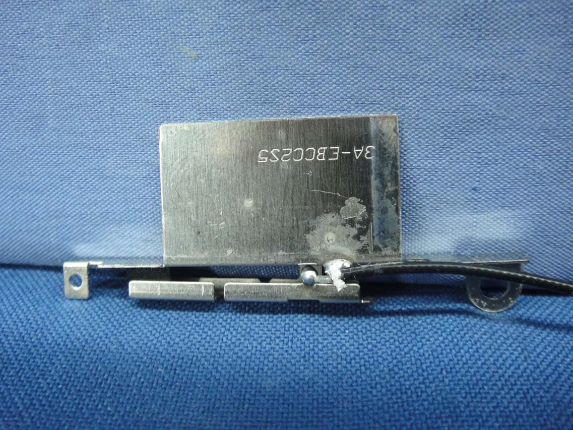
PPD-QCNFA364AH
May 27, 2015802.11a/b/g/n/ac + BT 4.1 M.2 2230 Type Card
Equipment Class
DTS - Digital Transmission System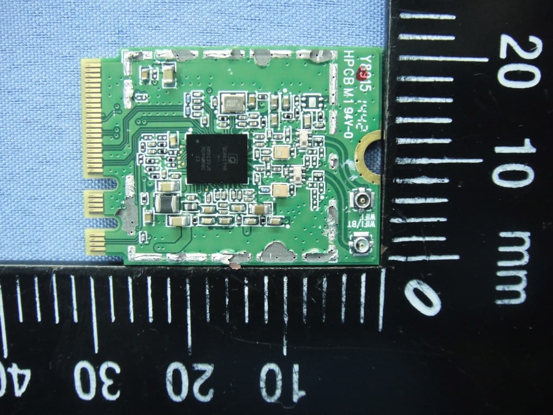
PPD-QCNFA344A
Apr 30, 2015802.11a/b/g/n/ac + BT 4.1 M.2 2230 Type Card
Equipment Class
NII - Unlicensed National Information Infrastructure TX