PQC-4843C1.4 GHz ACCESS POINT WITH REMOTE ANTENNA (ITS4843C)
Philips Medical Systems North America Co.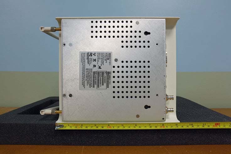
Click to zoom
Application Details
- Equipment Class
- TNB - Licensed Non-Broadcast Station Transmitter
- Date of Grant
- Aug 28, 2013
- Application Purpose
- Original Equipment
- Date of Application
- Aug 28, 2013
- Equipment Note
- 1.4 GHz ACCESS POINT WITH REMOTE ANTENNA (ITS4843C)
- Frequency Range
- 1427.90000000 - 1431.10000000
- Country
- United States
Documents & Files
Document Text
Text extracted from the exhibit documents filed with the FCC. Open a document above to read the original.
Users Manual
IntelliVue Smart-hopping 1.4 GHz High-power Access Point Installation Guide Part Number: 453564459791 Printed in the U.S.A. August, 2013 First Edition 453564459791 N e t w o r k p o w e r / S y n c R a d i o A c ti v i ty L i n k 10/100 48 VDC IOIOI Serial Service Port Draft - August 28, 2013 ii Proprietary Information This document contains proprietary information that is protected by copyright. Copyright Copyright © 2013 Koninklijke Philips N.V. All Rights Reserved. Manufacturer Philips Medical Systems 3000 Minuteman Road Andover, MA 01810-1099 (+1) 978-687-1501 This document was printed in the United States of America. Trademark Acknowledgements All trademarks, trade names and company names referenced herein are used for identification purposes only and are the property of their respective owners. FCC Notice These devices comply with part 15 of the FCC Rules. Operation is subject to the following two conditions: (1) these devices may not cause harmful interference, and (2) these devices must accept any interference received, including interference that may cause undesired operation. Pursuant to Part 15.21 of the FCC Rules, any changes or modifications to this equipment not expressly approved by Philips Medical Systems may cause harmful radio frequency interference, and void your authority to operate this equipment. This device has been designed to operate with the antenna having the part number 453564079561 and having a maximum gain of 3.2 dB. Antennas not included in this approved list or having a gain greater than 3.2 dB are strictly prohibited for use with this device. The required antenna impedance is 50 ohms. Warranty The information contained in this document is subject to change without notice. Philips Medical Systems makes no warranty of any kind with regard to this material, including, but not limited to, the implied warranties or merchantability and fitness for a particular purpose. Philips Medical Systems shall not be liable for errors contained herein or for incidental or consequential damages in connection with the furnishing, performance, or use of this material. Printing History New editions of this document will incorporate all material updated since the previous edition. The documentation printing date and part number indicate its current edition. The printing date and edition number change when a new edition is printed. The document part number changes when extensive technical changes are incorporated. First Edition ................................................................................................................................................... August, 2013 Draft - August 28, 2013 IntelliVue Smart-hopping 1.4 GHz High-power Access Point Installation Guideiii Contents Introduction . . . . . . . . . . . . . . . . . . . . . . . . . . . . . . . . . . . . . . . . . . . . . . . . . . . . . . . 1-2 A General Description of the IntelliVue Smart-hopping Core Access Point . . . . . 1-3 Core AP Mounting Options . . . . . . . . . . . . . . . . . . . . . . . . . . . . . . . . . . . . . . . . 1-4 Power Source . . . . . . . . . . . . . . . . . . . . . . . . . . . . . . . . . . . . . . . . . . . . . . . . . . 1-4 Synchronization Signal . . . . . . . . . . . . . . . . . . . . . . . . . . . . . . . . . . . . . . . . . . . 1-4 IntelliVue Patient Monitor Mobility . . . . . . . . . . . . . . . . . . . . . . . . . . . . . . . . . . 1-4 Technical Alerts . . . . . . . . . . . . . . . . . . . . . . . . . . . . . . . . . . . . . . . . . . . . . . . . . 1-5 Firmware Updates . . . . . . . . . . . . . . . . . . . . . . . . . . . . . . . . . . . . . . . . . . . . . . . 1-5 Management Interfaces . . . . . . . . . . . . . . . . . . . . . . . . . . . . . . . . . . . . . . . . . . 1-5 Connectors and Status Indicators . . . . . . . . . . . . . . . . . . . . . . . . . . . . . . . . . . . . . 1-6 IntelliVue Smart-hopping Core AP Connectors . . . . . . . . . . . . . . . . . . . . . . . . 1-6 Remote AP Connectors . . . . . . . . . . . . . . . . . . . . . . . . . . . . . . . . . . . . . . . . . . . 1-7 IntelliVue Smart-hopping Core AP Status LEDs. . . . . . . . . . . . . . . . . . . . . . . . 1-8 Remote Antenna Status LEDs . . . . . . . . . . . . . . . . . . . . . . . . . . . . . . . . . . . . . 1-8 Specifications. . . . . . . . . . . . . . . . . . . . . . . . . . . . . . . . . . . . . . . . . . . . . . . . . . . . . . 1-9 Ordering Information . . . . . . . . . . . . . . . . . . . . . . . . . . . . . . . . . . . . . . . . . . . . . . . 1-11 Regulatory Information . . . . . . . . . . . . . . . . . . . . . . . . . . . . . . . . . . . . . . . . . . . . . 1-12 Access Point Placement Guidelines . . . . . . . . . . . . . . . . . . . . . . . . . . . . . . . . . . . . 2-2 General Installation Procedure . . . . . . . . . . . . . . . . . . . . . . . . . . . . . . . . . . . . . . . . 2-3 Mounting the IntelliVue Smart-hopping Core AP to a Wall (Fixed Mount) . . . . . . 2-6 Mounting the IntelliVue Smart-hopping Core AP to a Wall (CA Earthquake Rated) . . . . . . . . . . . . . . . . . . . . . . . . . . . . . . . . . . . . . . . . . . . . . . 2-7 Mounting the IntelliVue Smart-hopping Core AP Above a Ceiling Tile . . . . . . . . . 2-9 Mounting the IntelliVue Smart-hopping Core AP Below a Ceiling Tile (Fixed Mount) . . . . . . . . . . . . . . . . . . . . . . . . . . . . . . . . . . . . . . . . . . . . . . . . . . . . . 2-12 Mounting the IntelliVue Smart-hopping Core AP Below a Ceiling Tile (Quick Release) . . . . . . . . . . . . . . . . . . . . . . . . . . . . . . . . . . . . . . . . . . . . . . . . . . . 2-16 Mounting the IntelliVue Smart-hopping Remote Antenna to a Wall (Fixed Mount) . . . . . . . . . . . . . . . . . . . . . . . . . . . . . . . . . . . . . . . . . . . . . . . . . . . . . 2-21 Mounting the IntelliVue Smart-hopping Remote Antenna to a Wall (CA Earthquake Rated) . . . . . . . . . . . . . . . . . . . . . . . . . . . . . . . . . . . . . . . . . . . . . 2-23 Mounting the IntelliVue Smart-hoppi…
Text truncated - open the document above for the full version.
Cover Letter(s)
Philips Medical Systems 3000 Minuteman Road Andover, MA 01810, USA Letter Of Agency Date: June2l,2013 To Whom It May Concern: Please be advised that Delroy Smith of Philips Medical Systems authorizes Larry Stillings of Compliance Worldwide, Inc. to act on our behalf, until otherwise notified, for applications submitted for the purpose of obtaining an FCC Grant of Equipment Authorization. We certify that we are not subject to denial of federal benefits, that includes FCC benefits, pursuant to Section 5301 of the Anti-Drug Abuse ACT of 1988, U.S.C. 862. Further, no party, as defined in 47 CFR 1.2002(b), to the application is subject to denial of federal benefits, that includes FCC benefits. Thank you for your attention to this matter. Signatory Delroy Smith Principal Scientist 1 -978-659-3382
Cover Letter(s)
Philips Medical Systems 3000 Minuteman Road Andover, MA 01810, USA Date: June 21, 2013 Federal Communications Commission Authorization and Evaluation Division Confidentiality Request regarding application for certification of FCC ID: PQC-4843C Pursuant to Sections 0.457 and 0.459 of the Commission’s Rules, we hereby request confidential treatment of information accompanying this application as outlined below: Exhibit Type File Name Block Diagram PQC-4843C BlkDia.pdf Schematics PQC-4843C Schem.pdf Operational Description PQC-4843C OpDes.pdf Tuning Procedure PQC-4843C TunPro.pdf Parts List PQC-4843C PartsLst.pdf The above materials contain trade secrets and proprietary information not customarily released to the public. The public disclosure of these materials may be harmful to the applicant and provide unjustified benefits to its competitors. The applicant understands that pursuant to Section 0.457 of the Rules, disclosure of this application and all accompanying documentation will not be made before the date of the Grant for this application. Pursuant to DAO4-1 705 June 15, 2004 of the Commission’s public notice, we also require temporary confidential treatment of information accompanying this application as outlined below: Exhibit Type File Name Internal Photos PQC-4843C lntPho.pdf Temporary confidentiality from public disclosure is important for Philips Medical Systems from a commercial perspective, It enables the company to complete its development and regulatory efforts prior to introducing the product to the marketplace. Releasing information on the product via the FCC website prior to formal market introduction can be confusing to our customers and the medical community, and places the company at a competitive disadvantage. Sincerely, Delroy Smith Principal Scientist 1 -978-659-3382 Philips Medical Systems 3000 Minuteman Road Andover, MA 01810, USA Letter Of Agency Date: June2l,2013 To Whom It May Concern: Please be advised that Delroy Smith of Philips Medical Systems authorizes Larry Stillings of Compliance Worldwide, Inc. to act on our behalf, until otherwise notified, for applications submitted for the purpose of obtaining an FCC Grant of Equipment Authorization. We certify that we are not subject to denial of federal benefits, that includes FCC benefits, pursuant to Section 5301 of the Anti-Drug Abuse ACT of 1988, U.S.C. 862. Further, no party, as defined in 47 CFR 1.2002(b), to the application is subject to denial of federal benefits, that includes FCC benefits. Thank you for your attention to this matter. Signatory Delroy Smith Principal Scientist 1 -978-659-3382
External Photos
External Photos ITS4843C Remote Antenna: Access point:
ID Label/Location Info
0 ASEE EDMRAS ISSUED06 OCT’10 453564239231-M-ADWG K.HOFFMAN 06 OCT’10 D. PECK 06 OCT’10 453564239211 453564239211-M-MART SMART-HOPPING 1.4 GHZ AP PRIMARY / PRODUCT I.D. LABEL ARTWORK (REFERENCE ONLY) K.HOFFMAN Made in the USA From Foreign and Domestic Components OPERATION OF THIS EQUIPMENT REQUIRES THE PRIOR COORDINATION WITH A FREQUENCY COORDINATOR DESIGNATED BY THE FCC FOR THE WIRELESS MEDICAL TELEMETRY SERVICE. THIS DEVICE COMPLIES WITH PART 15 OF THE FCC RULES. OPERATION IS SUBJECT TO THE FOLLOWING TWO CONDITIONS: (1) THAT THIS DEVICE MAY NOT CAUSE HARMFUL INTERFERENCE AND (2) THIS DEVICE MUST ACCEPT ANY INTER- FERENCE RECEIVED, INCLUDING INTERFERENCE THAT MAY CAUSE UNDESIRED OPERATION. NNNNNNNNNNNN GMDN: 37356 FCC ID: PQC-4843C NNNNNNNNNNNN USXXXXXXXX **NNNNNNNNNNNN **USXXXXXXXX MMMMMMMMMMMM *MMMMMMMMMMMM* Service # MMMMMMMMMMMM **NNNNNNNNNNNN *MMMMMMMMMMMM* 989803171211 ITS4843C Smart-hopping 1.4 GHz AP BSEE EDMR RE-LAYOUT TO REMOVE CE ! MARK & K.HOFFMAN REVISED FCC MARKING 16 NOV’10 CSEE EDMRREDIMENSIONED FOR TEARAWAY MAC ADDRESS 28 APR’10 K.HOFFMAN DSEE EDMRNEW MODEL # AND FCC ID 01 MAY’13 K.HOFFMAN Philips Medical Systems 3000 Minuteman Rd. Andover, MA 01810 USA
Internal Photos
Internal Photos ITS4843C Remote Antenna: Access point:
RF Exposure Info
Test Number: 311-13 Issue Date: 06/05/2013 Page 26 of 27 Compliance Worldwide, Inc. - 357 Main Street - Sandown, NH 03873 (603) 887 3903 Fax 887 6445 http://www.cw-inc.com 7. Measurement Data (continued) 7.7. Public Exposure to Radio Frequency Energy Levels (15.247(i) (1.1307 (b)(1)) RSS- GEN 5.5, RSS 102 1. The measured output power was calculated from the peak field strength measurements using the following equation: Frequency Peak Field Strength Distance Antenna Gain 1 Measured Output Power Channel (MHz) (dBμV/m) (m) (dBi) (mW) 1 1395.9 111.87 3.0 2.0 29.11 3 1399.1 110.78 3.0 2.0 22.65 4 1427.9 111.09 3.0 2.0 24.32 6 1431.1 111.38 3.0 2.0 26.00 1 Antenna gain value was supplied by the manufacturer (E x d) 2 (30 x G) P = the power in Watts. E = the measured maximum field strength in V/m G = the numeric gain of the transmitting antenna over an isotropic radiator. d = the distance in meters of the field strength measurement. 2. The DUT output power was derived from the measured output power in the above table to determine the power density. Power Density MPE Distance (cm) DUT Output Power (dBm) DUT Antenna Gain (dBi) (mW/cm2) (W/m2) Limit (mW/cm2) Channel Frequency (1) (2) (3) (4) (5) Result 1395.9 20.0 14.64 2.0 0.0091802 0.091802 0.93 Compliant 1399.1 20.0 13.55 2.0 0.0071425 0.071425 0.93 Compliant 1427.9 20.0 13.86 2.0 0.0076710 0.076710 0.95 Compliant 1431.1 20.0 14.15 2.0 0.0082007 0.082007 0.95 Compliant PD = Power Density (mW/cm 2 ) OP = DUT Output Power (dBm) AG = DUT Antenna Gain (dBi) d = MPE Distance (cm) 1. Reference CFR 2.1093(b): For purposes of this section, a portable device is defined as a transmitting device designed to be used so that the radiating structure(s) of the device is/are within 20 centimeters of the body of the user. 2. Section 7.1 of this test report. Output power was calculated from the measured field strength. 3. Antenna gain value for this product was taken from the client’s specification data sheet. 4. Power density is calculated from power measurement and antenna gain. 5. Reference CFR 1.1310, Table 1: Limits for Maximum Permissible Exposure (MPE), Section (B): Limits for General Population/Uncontrolled Exposure. OP + AG (4 x π x d²) PD = P =
RF Exposure Info
Test Number: 305-13 Issue Date: 05/31/2013 Page 29 of 30 Compliance Worldwide, Inc. - 357 Main Street - Sandown, NH 03873 (603) 887 3903 Fax 887 6445 http://www.cw-inc.com 7. Measurement Data (continued) 7.8. Public Exposure to Radio Frequency Energy Levels (15.247(i) (1.1307 (b)(1)) RSS- GEN 5.5, RSS 102 1. The measured output power was calculated from the peak field strength measurements using the following equation: Frequency Peak Field Strength Distance Antenna Gain 1 Measured Output Power Channel (MHz) (dBμV/m) (m) (dBi) (mW) 1 1395.9 111.66 3.0 2.0 27.74 3 1399.1 111.58 3.0 2.0 27.23 4 1427.9 111.54 3.0 2.0 26.98 6 1431.1 111.91 3.0 2.0 29.38 1 Antenna gain value was supplied by the manufacturer (E x d) 2 (30 x G) P = the power in Watts. E = the measured maximum field strength in V/m G = the numeric gain of the transmitting antenna over an isotropic radiator. d = the distance in meters of the field strength measurement. 2. The DUT output power was derived from the measured output power in the above table to determine the power density. Power Density MPE Distance (cm) DUT Output Power (dBm) DUT Antenna Gain (dBi) (mW/cm2) (W/m2) Limit (mW/cm2) Channel Frequency (1) (2) (3) (4) (5) Result 1395.9 20.0 14.43 2.0 0.0087468 0.0087468 0.93 Compliant 1399.1 20.0 14.35 2.0 0.0085872 0.0085872 0.93 Compliant 1427.9 20.0 14.31 2.0 0.0085085 0.0085085 0.95 Compliant 1431.1 20.0 14.68 2.0 0.0092651 0.0092651 0.95 Compliant PD = Power Density (mW/cm 2 ) OP = DUT Output Power (dBm) AG = DUT Antenna Gain (dBi) d = MPE Distance (cm) 1. Reference CFR 2.1093(b): For purposes of this section, a portable device is defined as a transmitting device designed to be used so that the radiating structure(s) of the device is/are within 20 centimeters of the body of the user. 2. Section 7.1 of this test report. Output power was calculated from the measured field strength. 3. Antenna gain value for this product was taken from the client’s specification data sheet. 4. Power density is calculated from power measurement and antenna gain. 5. Reference CFR 1.1310, Table 1: Limits for Maximum Permissible Exposure (MPE), Section (B): Limits for General Population/Uncontrolled Exposure. OP + AG (4 x π x d²) PD = P =
Test Report
Compliance Worldwide, Inc. - 357 Main Street - Sandown, NH 03873 (603) 887 3903 Fax 887 6445 http://www.complianceworldwide.com COMPLIANCE WORLDWIDE INC. TEST REPORT 311-13 In Accordance with the Requirements of Federal Communications Commission CFR 47 Part 95, Subpart H Wireless Medical Telemetry Devices In the bands 1395-1400 and 1427-1432 MHz Issued to Philips Medical Systems 3000 Minuteman Drive Andover, MA 01810 978-659-2800 for the ITS4843C Philips Telemetry System IntelliVue Access Point ITS4846A 1.4 GHz Remote Antenna FCC ID: PQC-4843C Report Issued on June 5, 2013 Tested by This test report shall not be reproduced, except in full, without written permission from Compliance Worldwide, Inc. Test Number: 311-13 Issue Date: 06/05/2013 Page 2 of 27 Compliance Worldwide, Inc. - 357 Main Street - Sandown, NH 03873 (603) 887 3903 Fax 887 6445 http://www.cw-inc.com Table of Contents 1. Scope........................................................................................................................................ 3 2. Product Details.......................................................................................................................... 3 2.1. Manufacturer ..................................................................................................................... 3 2.2. Model Number ................................................................................................................... 3 2.3. Serial Number.................................................................................................................... 3 2.4. Description......................................................................................................................... 3 2.5. Power Source .................................................................................................................... 3 2.6. EMC Modifications............................................................................................................. 3 3. Product Configuration ............................................................................................................... 3 3.1. Operational Characteristics & Software............................................................................. 3 3.2. EUT Hardware................................................................................................................... 3 3.3. EUT Cables/Transducers .................................................................................................. 3 3.4. Support Equipment............................................................................................................ 4 3.5. Support Equipment Cables/Transducers........................................................................... 4 3.6. Miscellaneous.................................................................................................................... 4 3.7. Block Diagram ................................................................................................................... 5 4. Measurements Parameters....................................................................................................... 6 4.1. Measurement Equipment Used to Perform Test ............................................................... 6 4.2. Measurement & Equipment Setup..................................................................................... 6 4.3. Test Procedure .................................................................................................................. 7 4.4. Measurement Uncertainty ................................................................................................. 7 5. Choice of Equipment for Test Suits ..........................................................................................7 5.1. Choice of Model................................................................................................................. 7 5.2. Presentation ...................................................................................................................... 7 5.3. Choice of Operating Frequencies ..................................................................................... 7 6. Measurement Summary............................................................................................................ 8 7. Measurement Data ................................................................................................................... 9 7.1. Radiated Field Strength of Fundamental ........................................................................... 9 7.2. Combined Radiated Field Strength of Harmonics ........................................................... 12 7.3. Occupied Bandwidth........................................................................................................13 7.4. Band Edge....................................................................................................................... 15 7.5. Spurious Radiated Emissions.......................................................................................... 17 7.6. Frequency Stability .......................................................................................................... 25 7.7. Public Exposure to Radio Frequency Energy Levels ...................................................... 26 8. Test Site Description............................................................................................................... 27 Test Number: 311-13 Issue Date: 06/05/2013 Page 3 of 27 Compliance Worldwide, Inc. - 357 Main Street - Sandown, NH 03873 (603) 887 3903 Fax 887 6445 http://www.cw-inc.com 1. Scope This test report certifies that the Philips IntelliVue ITS4846A 1.4 GHz Remote Antenna, as tested, meets the Federal Communications Commission CFR 47, PART 95 requirement. The scope of this test report is limited to the test sample provided by the client, only in as much as that sample represents other produc…
Text truncated - open the document above for the full version.
Test Report
Compliance Worldwide, Inc. - 357 Main Street - Sandown, NH 03873 (603) 887 3903 Fax 887 6445 http://www.complianceworldwide.com COMPLIANCE WORLDWIDE INC. TEST REPORT 305-13 In Accordance with the Requirements of Federal Communications Commission CFR 47 Part 95, Subpart H Wireless Medical Telemetry Devices In the bands 1395-1400 and 1427-1432 MHz Issued to Philips Medical Systems 3000 Minuteman Drive Andover, MA 01810 978-659-2800 for the ITS4843C IntelliVue Access Point Philips Telemetry System 1.4 GHz Access Point FCC ID: PQC-4843C Report Issued on May 31, 2013 Tested by This test report shall not be reproduced, except in full, without written permission from Compliance Worldwide, Inc. Test Number: 305-13 Issue Date: 05/31/2013 Page 2 of 30 Compliance Worldwide, Inc. - 357 Main Street - Sandown, NH 03873 (603) 887 3903 Fax 887 6445 http://www.cw-inc.com Table of Contents 1. Scope........................................................................................................................................ 3 2. Product Details.......................................................................................................................... 3 2.1. Manufacturer ..................................................................................................................... 3 2.2. Model Number ................................................................................................................... 3 2.3. Serial Number.................................................................................................................... 3 2.4. Description......................................................................................................................... 3 2.5. Power Source .................................................................................................................... 3 2.6. EMC Modifications............................................................................................................. 3 3. Product Configuration ............................................................................................................... 3 3.1. Operational Characteristics & Software............................................................................. 3 3.2. EUT Hardware................................................................................................................... 3 3.3. EUT Cables/Transducers .................................................................................................. 3 3.4. Support Equipment............................................................................................................ 4 3.5. Support Equipment Cables/Transducers........................................................................... 4 3.6. Miscellaneous.................................................................................................................... 4 3.7. Block Diagram ................................................................................................................... 5 4. Measurements Parameters....................................................................................................... 6 4.1. Measurement Equipment Used to Perform Test ............................................................... 6 4.2. Measurement & Equipment Setup..................................................................................... 6 4.3. Test Procedure .................................................................................................................. 7 4.4. Measurement Uncertainty ................................................................................................. 7 5. Choice of Equipment for Test Suits ..........................................................................................7 5.1. Choice of Model................................................................................................................. 7 5.2. Presentation ...................................................................................................................... 7 5.3. Choice of Operating Frequencies ..................................................................................... 7 6. Measurement Summary............................................................................................................ 8 7. Measurement Data ................................................................................................................... 9 7.1. Radiated Field Strength of Fundamental ........................................................................... 9 7.2. Combined Radiated Field Strength of Harmonics ........................................................... 12 7.3. Occupied Bandwidth........................................................................................................13 7.4. Band Edge....................................................................................................................... 15 7.5. Spurious Radiated Emissions.......................................................................................... 17 7.6. Frequency Stability .......................................................................................................... 25 7.7. Conducted Emissions...................................................................................................... 26 7.8. Public Exposure to Radio Frequency Energy Levels ...................................................... 29 8. Test Site Description............................................................................................................... 30 Test Number: 305-13 Issue Date: 05/31/2013 Page 3 of 30 Compliance Worldwide, Inc. - 357 Main Street - Sandown, NH 03873 (603) 887 3903 Fax 887 6445 http://www.cw-inc.com 1. Scope This test report certifies that the Philips IntelliVue 1.4 GHz Access Point, as tested, meets the Federal Communications Commission CFR 47, PART 95 requirement. The scope of this test report …
Text truncated - open the document above for the full version.
Test Setup Photos
Test Setup Photos ITS4843C Spurious Emissions Front Spurious Emissions Rear Field Strength Front Field Strength Rear Conducted Emission Front Conducted Emissions Rear
Test Setup Photos
Remote Antenna: Test Setup Photos ITS4843C Spurious Emissions Front Spurious Emissions Rear Field Strength Front Field Strength Rear
Contact Information
Applicant
Delroy Smith(Principal Architect)
Test Firm
Compliance Worldwide, Inc.Deb Bourbeau
Technical Specifications
| # | Rule Parts | Frequency Range | Power Output | Emission | Tolerance |
|---|---|---|---|---|---|
| 2 | 95H | 1.43 GHz - 1.43 GHz | 29.38 mW | 1M44L7D | 0.001663 % |
Other Applications from Philips Medical Systems North America Co.
PQC-AIM
Apr 14, 2024AIM
Equipment Class
DTS - Digital Transmission System
PQC-867216A
Jan 15, 2023Access Point
Equipment Class
DTS - Digital Transmission System
PQC-IITBV1
Mar 08, 20212.4G Radio Module
Equipment Class
DTS - Digital Transmission System
PQC-MX40SH1C4
Mar 31, 2014Intellivue MX40 1.4 GHz Patient Worn Device
Equipment Class
NII - Unlicensed National Information Infrastructure TX
PQC-OBRBSBV1
Nov 17, 2013CTG Base Station
Equipment Class
TNB - Licensed Non-Broadcast Station Transmitter