PQC-IITBV12.4G Radio Module
Philips Medical Systems North America Co.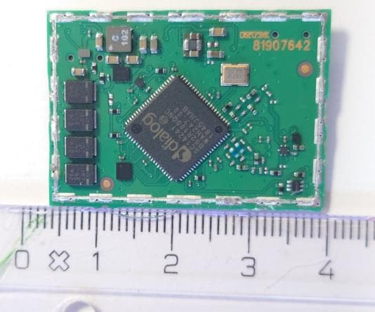
Click to zoom
Application Details
- Equipment Class
- DTS - Digital Transmission System
- Date of Grant
- Mar 08, 2021
- Application Purpose
- Original Equipment
- Date of Application
- Mar 08, 2021
- Equipment Note
- 2.4G Radio Module
- Frequency Range
- 2401.05600000 - 2482.27200000
- Country
- United States
Documents & Files
Document Text
Text extracted from the exhibit documents filed with the FCC. Open a document above to read the original.
Users Manual
_ _ IITBV1 ITS Module User’s Manual Manual Philips Medizin Systeme Böblingen GmbH Hewlett-Packard-Strasse 2, 71034 Böblingen, Germany, Tel +49(0)7031 463-0, Fax +49(0)7031 463-2202 Geschäftsführer: Dr. Dieter Haase (Sprecher), Dr. Peter Ziese, Matthijs de Groot Registergericht Stuttgart Reg.-Nr. HRB 245187, Sitz der Gesellschaft: Böblingen, www.philips.com/healthcare Product: IITBV1-ITS Module Model: IITBV1 FCC ID: PQC-IITBV1 IC: 3549A-IITBV1 For OEM integration only – device cannot be sold to general public. Therefore, we will not supply a User’s manual. We will ask OEM to include the following Notices required by FCC/ IC on the product and in the User’s manual. Notifications FCC ID: PQC-IITBV1 IC: 3549A-IITBV1 NOTICE Federal Communication Interference Statement (United States only) This equipment has been tested and found to comply with the limits for a class B digital device, pursuant to Part 15 of the FCC rules. These limits are designed to provide reasonable protection against harmful interference in a residential installation. This equipment generates, uses, and can radiate radio frequency energy and, if not installed and used in accordance with the instructions, may cause harmful interference to radio communications. However, there is no guarantee that interference will not occur in a particular installation. If this equipment does cause harmful interference to radio or television reception, which can be determined by turning the equipment off and on, the user is encouraged to try to correct the interference by one or more of the following measures: • Re-orient or relocate the receiving antenna • Increase the separation between the equipment and receiver _ _ • Connect the equipment to an outlet on a circuit different from that to which the receiver is connected • Consult the dealer or an experienced radio/TV technician for help This device and its antenna(s) must not be co-located or operation in conjunction with any other antenna or transmitter. Canadian Department of Communications Industry Canada Notice (Canada only) This Class B digital apparatus complies with Canadian ICES-003. Cet appareil numérique de la classe B est conforme à la norme NMB-003 du Canada. FCC Rules, Part 15/ Industry Canada This device complies with Part 15 of FCC Rules and Industry Canada licence-exempt RSS standard(s). Operation is subject to the following two conditions: • This device may not cause harmful interference, and • This device must accept any interference, including interference that may cause undesired operation of this device. Le présent appareil est conforme aux la partie 15 des règles de la FCC et CNR d'Industrie Canada applicables aux appareils radio exempts de licence. L'exploitation est autorisée aux deux conditions suivantes : l'appareil ne doit pas produire de brouillage, et l'utilisateur de l'appareil doit accepter tout brouillage radioélectrique subi, même si le brouillage est susceptible d'en compromettre le fonctionnement. This equipment complies with FCC/IC radiation exposure limits set forth for an uncontrolled environment and meets the FCC radio frequency (RF) Exposure Guidelines in Supplement C to OET65 and RSS-102 of the IC radio frequency (RF) Exposure rules. This equipment should be installed and operated keeping the radiator at least 20cm or more away from person’s body (excluding extremities: hands, wrists, feet and ankles). Cet équipement est conforme aux limites d’exposition aux rayonnements énoncées pour un environnement non contrôlé et respecte les règles les radioélectriques (RF) de la FCC lignes directrices d'exposition dans le Supplément C à OET65 et d’exposition aux fréquences _ _ radioélectriques (RF) CNR- 102 de l’IC. Cet équipement doit être installé et utilisé en gardant une distance de 20 cm ou plus entre le dispositif rayonnant et le corps (à l’exception des extrémités : mains, poignets, pieds et chevilles). Under Industry Canada regulations, this radio transmitter may only operate using an antenna of a type and maximum (or lesser) gain approved for the transmitter by Industry Canada. To reduce potential radio interference to other users, the antenna type and its gain should be so chosen that the equivalent isotropically radiated power (e.i.r.p.) is not more than that necessary for successful communication. Conformément à la réglementation d'Industrie Canada, le présent émetteur radio peut fonctionner avec une antenne d'un type et d'un gain maximal (ou inférieur) approuvé pour l'émetteur par Industrie Canada. Dans le but de réduire les risques de brouillage radioélectrique à l'intention des autres utilisateurs, il faut choisir le type d'antenne et son gain de sorte que la puissance isotrope rayonnée équivalente (p.i.r.e.) ne dépasse pas l'intensité nécessaire à l'établissement d'une communication satisfaisante. This radio transmitter 3549A-IITBV1 has been approved by Industry Canada to operate with the antenna types listed below with the maximum permissible gain and required antenna impedance for each antenna type indicated. Antenna types not included in this list, having a gain greater than the maximum gain indicated for that type, are strictly prohibited for use with this device. Le présent émetteur radio 3549A-IITBV1 a été approuvé par Industrie Canada pour fonctionner avec les types d'antenne énumérés ci-dessous et ayant un gain admissible maximal et l'impédance requise pour chaque type d'antenne. Les types d'antenne non inclus dans cette liste, ou dont le gain est supérieur au gain maximal indiqué, sont strictement interdits pour l'exploitation de l'émetteur. This device is going to be operated in 2400 MHz – 2483 MHz frequency range, it is restricted in indoor environment only. Frequency Tolerance:+/-10ppm _ _ WARNING: The FCC / The Industry Canada regulations provide that changes or modifications not expressly approved by the party responsible for compliance could void the user’s authority to operate the equipment. Manual and Product Labeling infor…
Text truncated - open the document above for the full version.
Cover Letter(s)
LONG-TERM CONFIDENTIALITY REQUEST for Certification Service in the USA Federal Communication Commission Equipment Authorization Division, Application Processing Branch 7435 Oakland Mills Road Columbia, MD 21048 TO WHOM IT MAY CONCERN Pursuant to Paragraphs $0.457 and 0.459 of the Commission's Rules (47 C.F.R.) and Section §552(6)%4) of the Freedom of Information Act, we request Long-Term Confidentialityfor the followingproduct: Grantee Code Equipment Product Code Check your GC here. Click Gramtee Search FCC ID: POC-IITBV1 For the product stated above, we request Long-Term Confidentiality for exhibits which contain Block Diagram, Operational Description, Parts List/Tune Up Info, Schematics, SDR Software/Security Info. The above exhibits contain our trade secrets and proprietary information that could be of benefit to our competitors. This informationwill not be publicly available. If you have any questions, please feel free to contact us at the address shown below. Sincerely, Company Philips Medizin Systeme Böblingen GmbH |Phone: +49 151 19615514 Name: Hewlett-Packard-Strasse 2 Fax: |+49 7031 463 2202 Company 71034 Boblingen [email protected] E-mail: Address: Germany Contact Stefan Breuer Name: Signature February 19, 2021 Date: Signature:| Document Version 2020-10-30
Cover Letter(s)
Modular Approval Attestation Federal Communication Commission Equipment Authorization Division, Application Processing Branch 7435 Oakland Mills Road Columbia, MD 21048 Certification and Engineering Bureau Innovation, Science and Economic Development Canada Spectrum Engineering Branch 3701 Carling Avenue, Building 94 Ottawa, Ontario K2H 882 Subject: FCC/ ISED Modular Approval Statement Check your CN here. Grantee Code Equipment Product Code Check your GC here. Click Grantee Search. FCC ID: PQC-IITBVI CN: UPN: 3549C IITBV (Company Number) (Unique Product Number) HVIN: (Hardware Version ld. Number) IITBV1 IITBVI PMN: (Product Marketing Name) HMN: N/A FVIN: 3.02 (Host Marketing Name) (Firmware Version ld. Number) TO WHOM IT MAY cONCERNN Pursuant to Paragraphs RSP-100, Issue 12 and CFR § 15.212, we herewith declare for our module. Yes No * Modular approval requirement (a) The radio elements shall have the radio frequency circuitry shielded. Physical/discrete and tuning capacitors may be located external to the shield, but shall be on the module assembly. Please provide a detailed explanation if the answer is "No.": (b) If the module has modulation/data input(s), they shall be buffered in order to ensure that the module will comply with the requirements set out in the applicable RadioStandards Specification (RSS)and Part 15 underconditions of excessive data rates or over-modulation. Pleaseprovidea detailed N/A explanation if the answer is "No.":NA (c) The module shall have its own powersupplyregulation on the module itself. This is to ensure that the module will comply with the requirements set out in the applicable standardregardless of the design of the power supplying circuitry in the host productthat housesthe module. Please providea detailed Power supply regulalion is provided by adapter board to the host device explanation if the answer is "No.":|e e s lor use n Grantec's host devices only and not for general sale (o) The module shall comply with the provisions for external power amplifiers and antennas detailed in the applicable RSS and rule part. The equlpment certification application shall contain: a dctaled descuption of the conliguratiom of highestantennagain for each type of trausnitting antemafor licence-exenmpt modules: the maxmun iransnitting antenna gain for licence modules, and a detauled descrsptuon of the eontyguration of lowest antenna puain for each type of receiving antennator Dyamie Frequency Selection (DFS) modules with removable antenna(s). Please provide a detailed N/A explanation if the answer is "No.": Modular approval requirement (e) The module shall be tested for compliance with the applicable standard in a stand-alone configuration i.c. the module shall not be inside another product during testing). Yes No* Please provide a detailed explanation if the answer is "No.":A (The module complics or will comply with applicable RSS- 102 exposure requirements and any applicable FCC RF exposure requirement ($8I.1307(b), 1.1310, 2.1091, and 2.1093) in its intended contiguration/integration in a host. Please provide a detailed explanation if the answer is "No.":A (g) The module must be labeled with its permanently affixed label (indicating ISED certisication number, HVIN and FCC identifier), or use an electronic display (see KDB Publication 784748 and RSP-100, section 5). N/A Please provide a detailed explanation if the answer is "No.":A (h) The module must comply with all specific rules applicable to the transmitter, including all the conditions provided in the integration instructions by the grante. Please provide a detailed explanation if the answer is "No.":NA i) (Only applicable for FCC) The module must contain a permanently attached antenna, or contain a unique antenna connector, and be marketed and operated only with specific antenna(s), per §§ 15.203, 15.204(b), 15,204(c). 15.212(a), 2.929(b). For further information concerning antenna connectors see: DA-00-1087. *Please provide a detailed explanation if the answer is "No.":NA N/A If you have any questions, please feel free to contact us at the address shown below Best regards, Company Philips Medizin Systeme Böblingen GmbH | Phone: Name: +49 151 19615514 Hewlett-Packard-Strasse2 Fax: +49 7031 463 2202 Company 71034 Böblingen [email protected] E-mail: Address: Germany Contact Stefan Breuer Name: Signature Signature: March 05, 2021 Date: INFO for upplicant: Limited Modolar Approval (LMA) may be granted when one or more of the requirementsin he table above cannot be demonstrated. LMA will also be issued in those instances where applicants can demonstrate that they will retain control over the final installation of the device, such that compliance of the end product is assured. In such cases, an operating condition on the LMA for the module must state that the module is only approved for use when installed in devices produced by a specificmanufacturer. When LMA is sought, the application for equipment certification must specifically state how control of the end produet, into which the module will be installed, will be maintained,such that ful compliance of the end product is always ensured.
Cover Letter(s)
PHILIPS Federal Communication Commission Equipment Authorization Division, Application Processing Branch 7435 Oakland Mills Road Philips Medizin Systeme Böblingen GmbH Regulatory and Clinical Affairs Monitoring & Analytics and Therapeutic Care Columbia, MD 21048 Certification and Engineering Bureau Innovation, Science and Economic Development Canada Spectrum Engineering Branch 3701 Carling Avenue, Building 94 +49 151/1961 5514 49 7031/463-2202 [email protected] Ottawa, Ontario K2H 852 01 March 2021 ATTESTATION STATEMENT To whom it may concern: We, Philips Medizin Systeme Böblingen GmbH, declare on our sole responsibility that the model ITBV1 with IC Certification Number: 3549C-IITBVvi FCC ID:PQC-IITBV1 is only approved for use by grantee in its own products and not intended for sale to third parties and that the user manual integration instructions are internal confidential manufacturing documents according to KDB 996369 D03, February 1, 2019. If you have any questions, please feel free to contact us at the address shown below Yours faithfully, Stefan Byéuer Senior Regulatory Affairs Engineer Philips Medizin Systeme Böblingen GmbH PHILIPS Philips Medizin Systemne Böblingen GmbH Hewlett-Pacard Strale 2, 71034 Boblingen, Germany, Telefon +49(0)/031 463 0, Ielefax +49(0)703 1 463-2202 Geschaftsführer:Dr. Dieter Haase (Sprecher), Dr. Peter Ziese, Matthijs de Giroot Registergericht Stuttgart Reg. Nr. HRB 245187, Sitz cder Gesellschaft: Boblingen www.philips.com/healthcare
External Photos
_ _ IITBV1 ITS Module Photos Manual Top Bottom No Shield
External Photos
Annex A 1-1037/20-01-01_AnnexA External photos of the Equipment Under Test This addendum is electronically signed and valid without handwritten signature. For verification of the electronic signatures, the public keys can be requested at the testing laboratory. Document authorized: Marco Bertolino Lab Manager Radio Communications & EMC CTC advanced GmbHUntertuerkheimer Str. 6-10 66117 Saarbruecken / Germany Phone: +49 681 5 98 - 0 Fax: +49 681 5 98 - 9075 web: ctcadvanced.com e-mail: [email protected] Photos Photo 1: Module front side Photo 2: Module back side 2020-10-27Document No. 1-1037/20-01-01_AnnexA2/11 Photo 3: Interface Photo 4: Interface 2020-10-27Document No. 1-1037/20-01-01_AnnexA3/11 Photo 5: Interface Photo 6: Interface 2020-10-27Document No. 1-1037/20-01-01_AnnexA4/11 Photo 7: Interface Photo 8: Power supply 2020-10-27Document No. 1-1037/20-01-01_AnnexA5/11 Photo 9: Power supply Photo 10: Power supply 2020-10-27Document No. 1-1037/20-01-01_AnnexA6/11 Photo 11: Antenna Apollo Photo 12: Antenna Apollo 2020-10-27Document No. 1-1037/20-01-01_AnnexA7/11 Photo 13: Antenna Apollo Photo 14: Antenna Apollo 2020-10-27Document No. 1-1037/20-01-01_AnnexA8/11 Photo 15: Antenna Delphi Photo 16: Antenna Delphi 2020-10-27Document No. 1-1037/20-01-01_AnnexA9/11 Photo 17: Antenna Delphi Photo 18: Antenna Delphi 2020-10-27Document No. 1-1037/20-01-01_AnnexA10/11 Document history VersionApplied changesDate of release initial release2020-10-27 - END OF DOCUMENT - 2020-10-27Document No. 1-1037/20-01-01_AnnexA11/11
Internal Photos
_ _ IITBV1 ITS Module Photos Manual Top Bottom No Shield
Internal Photos
Annex B 1-1037/20-01-01_AnnexB Internal photos of the Equipment Under Test This addendum is electronically signed and valid without handwritten signature. For verification of the electronic signatures, the public keys can be requested at the testing laboratory. Document authorized: Marco Bertolino Lab Manager Radio Communications & EMC CTC advanced GmbHUntertuerkheimer Str. 6-10 66117 Saarbruecken / Germany Phone: +49 681 5 98 - 0 Fax: +49 681 5 98 - 9075 web: ctcadvanced.com e-mail: [email protected] Photos Photo 1 2021-02-23Document No. 1-1037/20-01-01_AnnexB2/3 Document history VersionApplied changesDate of release initial release2021-02-23 - END OF DOCUMENT - 2021-02-23Document No. 1-1037/20-01-01_AnnexB3/3
RF Exposure Info
© CTC advanced GmbH Page 1 of 3 BNetzA - CAB - 02/21 - 102 D - P L - 1 2 0 7 6 - 0 1 - 0 3 Maximum Permissible Exposure (MPE) & Exposure evaluation Report identification number: 1-1037/20-01-04-A MPE (FCC_ISED) Certification numbers and labeling requirements FCC ID PQC-IITBV1 ISED number 3549C-IITBV1 HVIN (Hardware Version Identification Number) IITBV1 PMN (Product Marketing Name) IITBV1 FVIN (Firmware Version Identification Number) 3.02 HMN (Host Marketing Name) -/- This report is electronically signed and valid without handwriting signature. For verification of the electronic signatures, the public keys can be requested at the testing laboratory. Document authorised: Alexander Hnatovskiy Marco Scigliano Lab Manager Testing Manager Radio Communications & EMC Radio Communications & EMC Report no.: 1-1037/20-01-04-A © CTC advanced GmbH Page 2 of 3 EUT technologies: Technologies: Max. power [dBm] Antenna gain max.: [dBi] Declared by customer # conducted EIRP Proprietary 2450 MHz Antenna type 1 14.6 15.7 1.1 15.7 dBm A Proprietary 2450 MHz Antenna type 2 14.6 18.3 3.7 18.3 dBm A Details and origins of the measurements shown in the table above: A 1-1037/20-01-02 CTC advanced GmbH report Antenna Gains on page 22, Max conducted on page 26. Antenna type 1: Philips 453564817421 Antenna, for X3 and MX100 Antenna type 2: Philips 453564271931 Antenna, for MX400, MX450, MX500, MX550 Prediction of MPE limit at given distance - FCC Equation from page 18 of OET Bulletin 65, Edition 97-01 S = PG / 4π R 2 where: S = Power density P = Power input to the antenna G = Antenna gain R = Distance to the center of radiation of the antenna PG = Output Power including antenna gain The table below is excerpted from Table 1B of 47 CFR 1.1310 titled “Limits for Maximum Permissible Exposure (MPE), Limits for General Population/Uncontrolled Exposure” Frequency Range (MHz) Power Density (mW/cm 2 ) Averaging Time (minutes) 300 -1500 f/1500 30 1500 - 100000 1.0 30 where f = Frequency (MHz) Prediction: worst case PGDeclared max power (EIRP)18.3dBm RDistance20cm SMPE limit for uncontrolled exposure1 mW/cm 2 Calculated Power density:0.0135mW/cm² Calculated percentage of Limit: 1.35% This prediction demonstrates the following: The power density levels for FCC at a distance of 20 cm are below the maximum levels allowed by regulations. Report no.: 1-1037/20-01-04-A © CTC advanced GmbH Page 3 of 3 Prediction of MPE limit at given distance - ISED RSS-102, Issue 5, 2.5.2 RF exposure evaluation is required if the separation distance between the user and/or bystander and the device’s radiating element is greater than 20 cm, except when the device operates as follows: • below 20 MHz and the source-based, time-averaged maximum e.i.r.p. of the device is equal to or less than 1 W (adjusted for tune-up tolerance); • at or above 20 MHz and below 48 MHz and the source-based, time-averaged maximum e.i.r.p. of the device is equal to or less than 4.49/ƒ 0.5 W (adjusted for tune-up tolerance), where ƒ is in MHz; • at or above 48 MHz and below 300 MHz and the source-based, time-averaged maximum e.i.r.p. of the device is equal to or less than 0.6 W (adjusted for tune-up tolerance); • at or above 300 MHz and below 6 GHz and the source-based, time-averaged maximum e.i.r.p. of the device is equal to or less than 1.31 x 10 -2 ƒ 0.6834 W (adjusted for tune-up tolerance), where ƒ is in MHz; • at or above 6 GHz and the source-based, time-averaged maximum e.i.r.p. of the device is equal to or less than 5 W (adjusted for tune-up tolerance). Prediction: worst case Frequency 2450 MHz R Distance 20 cm P Max power input to the antenna 14.6 dBm G Antenna gain 3.7 dBi P G Maximum EIRP 18.3 dBm P G Maximum EIRP 67.6 mW Exclusion Limit from above: 2.71 W Calculated percentage of Limit: 2.49 % Conclusion: RF exposure evaluation is not required.
Test Report
Measurement Results 1-1037/20-01-02_log1_conducted Test logging This addendum is electronically signed and valid without handwritten signature. For verification of the electronic signatures, the public keys can be requested at the testing laboratory. Document authorized: Mihail Dorongovskij Lab Manager Radio Communications CTC advanced GmbHUntertuerkheimer Strasse 6-10 66117 Saarbruecken / Germany Phone: +49 681 5 98 - 0 Fax: +49 681 5 98 - 9075 web: ctcadvanced.com e-mail: [email protected] Table of Content IUT Summary3 1. FCC Part 15.247 Maximum Peak Conducted Output Power DTS ~ Generic 2G44 2. FCC Part 15.247 Maximum Peak Conducted Output Power DTS ~ Generic 2G47 3. FCC Part 15.247 Maximum Peak Conducted Output Power DTS ~ Generic 2G410 4. FCC Part 15.247 Bandwidth 6dB DTS ~ Generic 2G413 5. FCC Part 15.247 Bandwidth 6dB DTS ~ Generic 2G415 6. FCC Part 15.247 Bandwidth 6dB DTS ~ Generic 2G417 7. FCC Part 15.247 Peak Power Spectral Density DTS ~ Generic 2G419 8. FCC Part 15.247 Peak Power Spectral Density DTS ~ Generic 2G421 9. FCC Part 15.247 Peak Power Spectral Density DTS ~ Generic 2G423 10. FCC Part 15.247 Bandwidth 99PCT-20dB ~ Generic 2G425 11. FCC Part 15.247 Bandwidth 99PCT-20dB ~ Generic 2G428 12. FCC Part 15.247 Bandwidth 99PCT-20dB ~ Generic 2G431 13. FCC Part 15.247 TX Spurious Conduced ~ Generic 2G434 14. FCC Part 15.247 Maximum Peak Conducted Output Power DTS ~ Generic 2G438 15. FCC Part 15.247 Bandwidth 6dB DTS ~ Generic 2G441 16. FCC Part 15.247 Peak Power Spectral Density DTS ~ Generic 2G443 17. FCC Part 15.247 Bandwidth 99PCT-20dB ~ Generic 2G445 18. FCC Part 15.247 TX Spurious Conduced ~ Generic 2G448 19. FCC Part 15.247 Maximum Peak Conducted Output Power DTS ~ Generic 2G450 20. FCC Part 15.247 Bandwidth 6dB DTS ~ Generic 2G453 21. FCC Part 15.247 Peak Power Spectral Density DTS ~ Generic 2G455 22. FCC Part 15.247 Bandwidth 99PCT-20dB ~ Generic 2G457 23. FCC Part 15.247 TX Spurious Conduced ~ Generic 2G460 Document No. 1-1037/20-01-02_log1_conducted2/61 IUT Summary IUT DEFINITION & Common settings ManufacturerPhilips Medizin Systeme Böblingen GmbH Type2.4G SH1.0 Radio Serial No. | Setup No.000378 | 1.0 SW Version | HW Version3.02 | 2016 Comment 1 | 2 | Tlow | Tmid | Thigh [°C] 0 | 20 | 70 Vlow | Vmid | Vhigh [V] @Imax [A] 3.2 | 3.3 | 3.45 @1 Auto Control enabled Power Supply | Climatic BoxNo | No Antenna Gain [dBi] (only considered if explicitly mentioned in testresult)0 Additional Path Loss [dB]0.7 IUT Common Settings 2G4 Hopping supported No Burst length [ms]1 Nominal Bandwidth [MHz]1.4 User InteractionNo Document No. 1-1037/20-01-02_log1_conducted3/61 1. FCC Part 15.247 Maximum Peak Conducted Output Power DTS ~ Generic 2G4 Test References TC Start07.10.2020 17:21:00 Ambit Temp [°C] | Humidity [rel%] 28.0 | 34 System Version1.0.0.51 Test SpecificationFCC Part 15.247 Test MethodDTS: KDB 558074 D01 V05 - Chapter 8.3.1.1 RBW ≥ DTS Bandwidth Class / TC VersionTC_VM_FCC15247_Maximum_Peak_Conducted_Output_Power_DTS_V01 Version: 0.0.1 My DescriptionFCC 15.247 Maximum Peak Output Power Conducted DTS4 - Generic 2G4 Add. Information Test Parameter Technology to testGeneric 2G4 Antenna Port used1 Temperaturemid Voltagemid Frequency low to testTrue | Freq [MHz] 2401.056 Frequency mid to testFalse | Freq [MHz] 2440.8 Frequency high to testFalse | Freq [MHz] 2482.272 Switched PathIUT - SignalingUnit - SpectrumAnalyzer Devices in use | SA: Rohde&Schwarz,FSV-30,1321.3008K30/103170,3.60 Document No. 1-1037/20-01-02_log1_conducted4/61 Test at TX 2401.056 MHz READ SA SETTINGS: RefLevel [dBm] | RefLevelOffset [dB] | InpAtt [dB]18.36 | 10.91 | 25 Start [MHz] | Stop [MHz]2399.656 | 2402.456 RBW [MHz] | VBW [MHz]0.100000 | 0.300000 Detector | TraceModePOS | MAXH Sweep: Time [ms] | Count | Points per Section | Type50 | 200 | 10001 | SWE DTS Bandwidth Test DescriptionLower LimitUpper LimitMeasuredUnitVerdict DTS Bandwidth (6dB)------807kHzINFO Plot_FCC Part 15.247 Maximum Peak Conducted Output Power DTS ~ Generic 2G4 DTS BW_07102020_172127.png READ SA SETTINGS: RefLevel [dBm] | RefLevelOffset [dB] | InpAtt [dB]23.36 | 10.91 | 30 Start [MHz] | Stop [MHz]2399.656 | 2402.456 RBW [MHz] | VBW [MHz]2.000000 | 5.000000 Detector | TraceModePOS | MAXH Sweep: Time [ms] | Count | Points per Section | Type50 | 200 | 1001 | SWE RESULT Test DescriptionLower LimitUpper LimitMeasuredUnitVerdict Peak Power---30.0014.57dBmPASS Peak Power---100028.64178mWPASS Frequency at Peak------2400.799MHzINFO Document No. 1-1037/20-01-02_log1_conducted5/61 Plot_FCC Part 15.247 Maximum Peak Conducted Output Power DTS ~ Generic 2G4_07102020_172144.png TEST FINISHED General Verdict07.10.2020 17:21:44 / RT: 44 sPASS Document No. 1-1037/20-01-02_log1_conducted6/61 2. FCC Part 15.247 Maximum Peak Conducted Output Power DTS ~ Generic 2G4 Test References TC Start07.10.2020 17:31:08 Ambit Temp [°C] | Humidity [rel%] 28.0 | 34 System Version1.0.0.51 Test SpecificationFCC Part 15.247 Test MethodDTS: KDB 558074 D01 V05 - Chapter 8.3.1.1 RBW ≥ DTS Bandwidth Class / TC VersionTC_VM_FCC15247_Maximum_Peak_Conducted_Output_Power_DTS_V01 Version: 0.0.1 My DescriptionFCC 15.247 Maximum Peak Output Power Conducted DTS4 - Generic 2G4 Add. Information Test Parameter Technology to testGeneric 2G4 Antenna Port used1 Temperaturemid Voltagemid Frequency low to testFalse | Freq [MHz] 2401.056 Frequency mid to testTrue | Freq [MHz] 2440.8 Frequency high to testFalse | Freq [MHz] 2482.272 Switched PathIUT - SignalingUnit - SpectrumAnalyzer Devices in use | SA: Rohde&Schwarz,FSV-30,1321.3008K30/103170,3.60 Document No. 1-1037/20-01-02_log1_conducted7/61 Test at TX 2440.8 MHz READ SA SETTINGS: RefLevel [dBm] | RefLevelOffset [dB] | InpAtt [dB]18.31 | 10.99 | 25 Start [MHz] | Stop [MHz]2439.400 | 2442.200 RBW [MHz] | VBW [MHz]0.100000 | 0.300000 Detector | TraceModePOS | MAXH Sweep: Time [ms] | Count | Points per Section | Type50 | 200 | 10001 | SWE DTS Bandwidth Test DescriptionLower LimitUpper LimitMeasuredUnitVerdict DTS Bandwidth (6dB)------80…
Text truncated - open the document above for the full version.
Test Report
TEST REPORT Test report no.: 1-1037/20-01-02-B Testing laboratory Applicant CTC advanced GmbH Untertuerkheimer Strasse 6 – 10 66117 Saarbruecken / Germany Phone: + 49 681 5 98 - 0 Fax: + 49 681 5 98 - 9075 Internet: https://www.ctcadvanced.com e-mail: [email protected] Accredited Testing Laboratory: The testing laboratory (area of testing) is accredited according to DIN EN ISO/IEC 17025 (2018- 03) by the Deutsche Akkreditierungsstelle GmbH (DAkkS) The accreditation is valid for the scope of testing procedures as stated in the accreditation certificate starting with the registration number: D-PL-12076-01. Philips Medizin Systeme Böblingen GmbH Hewlett-Packard-Strasse 2 71034 Böblingen / GERMANY Phone: +49 7031 463 1879 Contact: Hansjörg Geywitz e-mail: [email protected] Phone: -/- Manufacturer Philips Medizin Systeme Böblingen GmbH Hewlett-Packard-Strasse 2 71034 Böblingen / GERMANY Test standard/s FCC - Title 47 CFR Part 15 FCC - Title 47 of the Code of Federal Regulations; Chapter I; Part 15 - Radio frequency devices RSS - 247 Issue 2 Digital Transmission Systems (DTSs), Frequency Hopping Systems (FHSs) and Licence - Exempt Local Area Network (LE-LAN) Devices For further applied test standards please refer to section 3 of this test report. Test Item Kind of test item: 2.4G Radio Module Model name: IITBV1 FCC ID: PQC-IITBV1 IC: 3549C-IITBV1 Frequency: DTS band 2400 MHz to 2483.5 MHz Technology tested: Proprietary Antenna: External Antenna Power supply: 3.3 V DC by external power supply Temperature range: 0°C to +70°C This test report is electronically signed and valid without handwritten signature. For verification of the electronic signatures, the public keys can be requested at the testing laboratory. Test report authorized: Test performed: Andreas Luckenbill Michael Dorongovski Head of Department Lab Manager Radio Communications Radio Communications Test report no.: 1-1037/20-01-02-B © CTC advanced GmbH Page 2 of 63 1 Table of contents 1 Table of contents ....................................................................................................................................... 2 2 General information ................................................................................................................................... 4 2.1 Notes and disclaimer....................................................................................................................... 4 2. 2 Application details .......................................................................................................................... 4 2.3 Test laboratories sub-contracted .................................................................................................... 4 3 Test standard/s, references and accreditations ......................................................................................... 5 4 Reporting statements of conformity – decision rule .................................................................................. 6 5 Test environment ....................................................................................................................................... 7 6 Test item ................................................................................................................................................... 7 6.1 General description ......................................................................................................................... 7 6.2 Additional information..................................................................................................................... 8 7 Sequence of testing ................................................................................................................................... 9 7.1 Sequence of testing radiated spurious 9 kHz t…
Text truncated - open the document above for the full version.
Contact Information
Applicant
Delroy Smith(Principal Architect)
Test Firm
cetecom advanced GmbHGerald Schmidt
Technical Specifications
| # | Rule Parts | Frequency Range | Power Output |
|---|---|---|---|
| 1 | 15C | 2.40 GHz - 2.48 GHz | 28.84 mW |
Other Applications from Philips Medical Systems North America Co.
PQC-AIM
Apr 14, 2024AIM
Equipment Class
DTS - Digital Transmission System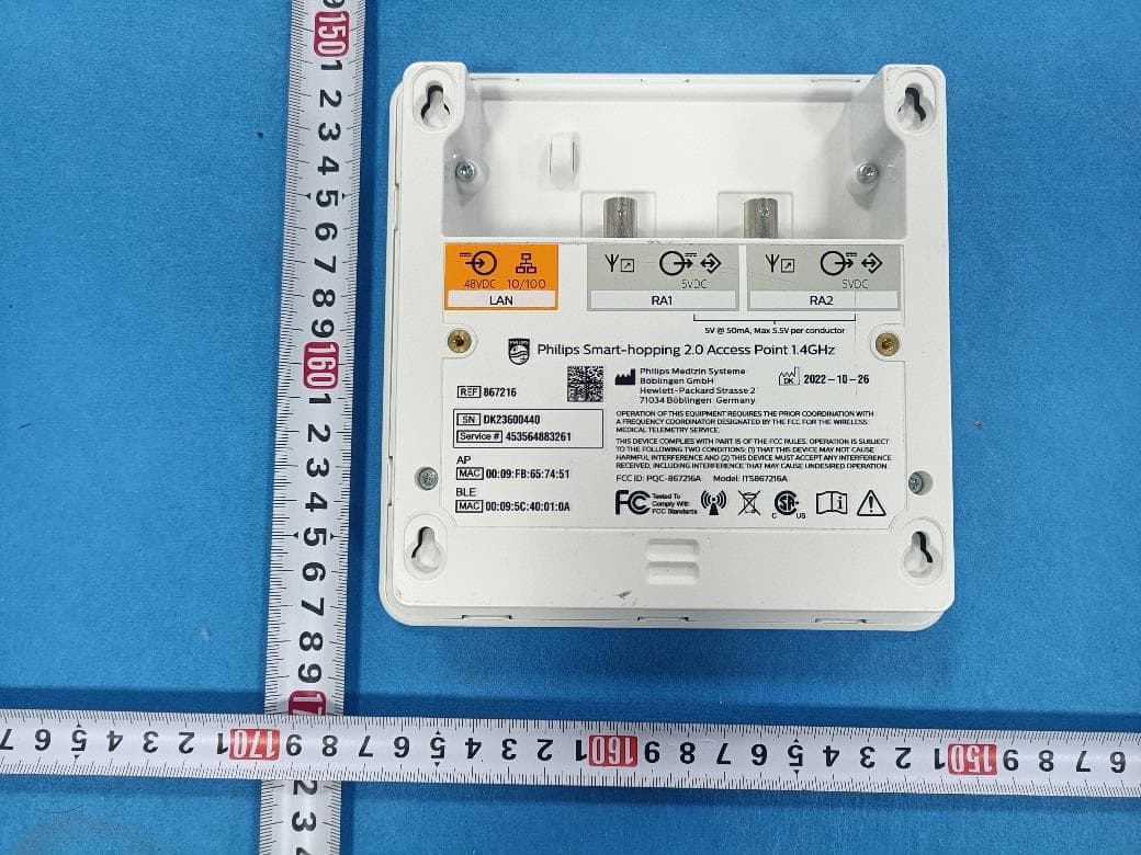
PQC-867216A
Jan 15, 2023Access Point
Equipment Class
DTS - Digital Transmission System
PQC-MX40SH1C4
Mar 31, 2014Intellivue MX40 1.4 GHz Patient Worn Device
Equipment Class
NII - Unlicensed National Information Infrastructure TX
PQC-OBRBSBV1
Nov 17, 2013CTG Base Station
Equipment Class
TNB - Licensed Non-Broadcast Station Transmitter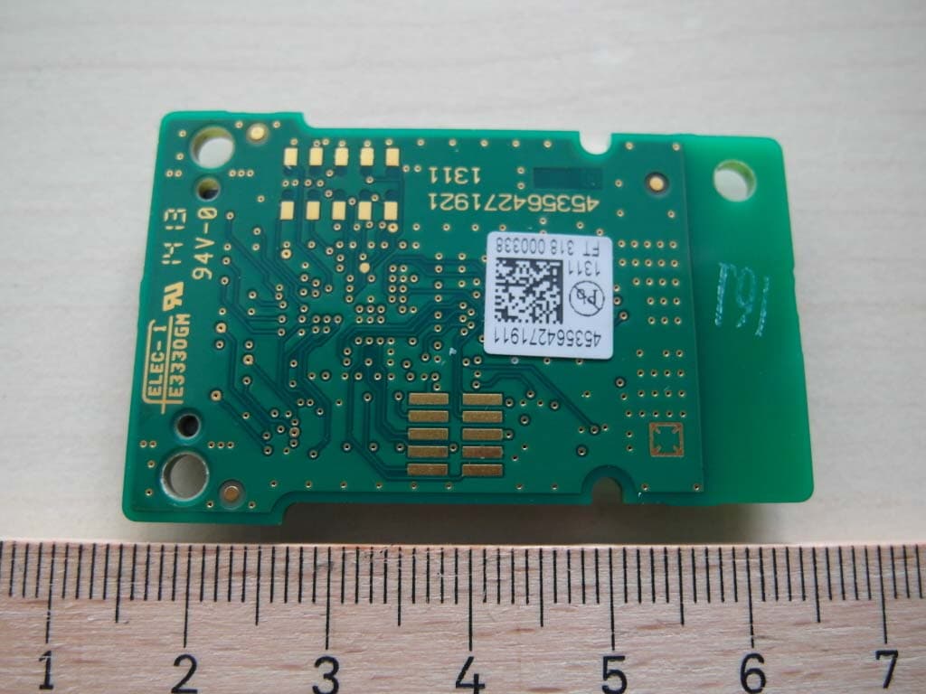
PQC-SRRBV3
Nov 17, 2013SRR Module
Equipment Class
DTS - Digital Transmission System