PQC-OBRBSBV1CTG Base Station
Philips Medical Systems North America Co.
Click to zoom
Application Details
- Equipment Class
- TNB - Licensed Non-Broadcast Station Transmitter
- Date of Grant
- Nov 17, 2013
- Application Purpose
- Original Equipment
- Date of Application
- Nov 17, 2013
- Equipment Note
- CTG Base Station
- Frequency Range
- 608.37500000 - 613.62500000
- Country
- United States
Documents & Files
Document Text
Text extracted from the exhibit documents filed with the FCC. Open a document above to read the original.
Users Manual
Instructions for Use Avalon Fetal Monitor FM20/30, FM40/50, Avalon CL Release J.3. with Software Revision J.30.xx Patient Monitoring 3 1Table of Contents 1Introduction9 Who this Book is For9 Confirm Fetal Life Before Using the Monitor10 Introducing the Avalon Family of Fetal Monitors11 2What's New29 What's New in Release J.329 What's New in Release G.032 3Basic Operation35 Supported Measurements35 Avalon FM20 and FM3036 Avalon FM40 and FM5039 Avalon CL Transducer System40 Getting to Know Your Avalon FM20/FM3040 Getting to Know Your Avalon FM40/FM5043 Transducers45 Getting to Know Your Avalon CL47 Cableless Transducers51 CL Pods55 Operating and Navigating56 Operating Modes63 Automatic Screen Layouts64 Settings64 Preparing to Monitor67 Switching the Monitor to Standby98 After Monitoring98 Disconnecting from Power99 Power On/Power Off Behavior99 Monitoring After a Power Failure99 Troubleshooting100 4FM20/30 Battery Option101 External Power Supply M8023A102 Using Batteries102 Optimizing Battery Performance105 5Alarms109 Alarm Mode110 Nurse Call Systems110 4 Visual Alarm Indicators110 Audible Alarm Indicators111 Acknowledging Alarms114 Acknowledging Disconnect INOPs114 Alarm Reminder114 Pausing or Switching Off Alarms115 Alarm Limits117 Reviewing Alarms118 Latching Alarms118 Testing Alar ms120 Alarm Behavior at Power On121 6Patient Alarms and INOPs123 Alarm Messages123 Technical Alarm Messages (INOPs)126 7Admitting and Discharging137 Admit/Discharge on the Monitor137 New Patient Check139 OB TraceVue/IntelliSpace Perinatal139 8Non-Stress Test Timer141 Setting NST Autostart/Autostop141 Viewing the NST Timer141 Timer Expiry Notification142 Accessing the NST Setup Pop-up Keys142 9Non-Stress Test Report145 Setting Up an NST Report145 NST Report Status Window146 NST Criteria148 Non-Reassuring Report149 Non-Reactive NST Test149 10Cross-Channel Verification (CCV)151 Misidentification of Heart Rates151 Cross-Channel Verification Functionality152 Overview of Cross-Channel Comparisons152 Coincidence Examples154 Recommended Actions for INOP Coincidence156 11Monitoring FHR and FMP Using Ultrasound157 Technical Description157 Limitations of the Technology158 Misidentification of MHR as FHR158 What You Need158 5 Cableless Monitoring - Important Considerations159 Preparing to Monitor160 Selecting Fetal Heart Sound161 Changing the Fetal Heart Sound Volume161 Fetal Movement Profile163 Troubleshooting165 Additional Information166 Testing Ultrasound Transducers173 12Monitoring Twin FHRs175 Important Considerations175 Monitoring Twins Externally176 Monitoring Twins Internally177 Separating FHR Traces177 Troubleshooting181 13Monitoring Triple FHRs183 Important Considerations183 Monitoring Triplets184 Separating FHR Traces184 "Standard" Separation Order184 "Classic" Separation Order185 Switching Trace Separation On and Off186 When Trace Separation is On187 When Trace Separation is Off188 Troubleshooting188 14Fetal Heart Rate Alarms191 Changing Alarm Settings191 Changing Signal Loss Delay192 15Monitoring Uterine Activity Externally193 What You Need193 External Toco Monitoring194 Toco Sensitivity195 Troubleshooting195 Testing Toco Transducers195 16Monitoring Uterine Activity Internally197 What You Need197 Internal (IUP) Monitoring199 Troubleshooting199 17Monitoring FHR Using DECG201 Misidentification of MHR as FHR201 What You Need203 6 Making Connections205 Monitoring DECG206 Suppressing Artifacts208 Troubleshooting209 Testing DECG Mode209 18Monitoring Noninvasive Blood Pressure211 Introducing the Oscillometric Noninvasive Blood Pressure Measurement211 Preparing to Measure Noninvasive Blood Pressure212 Starting and Stopping Measurements214 Enabling Automatic Mode and Setting Repetition Time215 Enabling Sequence Mode and Setting Up The Sequence215 Choosing the Alarm Source216 Assisting Venous Puncture216 Calibrating NBP216 Troubleshooting217 19Monitoring Maternal Temperature219 Measuring Tympanic Temperature219 20Monitoring SpO2227 Selecting an SpO2 Sensor227 Applying the Sensor227 Connecting SpO2 Cables228 Measuring SpO2228 SpO2 Signal Quality Indicator (Fast SpO2 only)229 Assessing a Suspicious SpO2 Reading230 Understanding SpO2 Alarms230 Setting Up Tone Modulation231 Setting the QRS Volume231 21Monitoring Maternal Heart / Pulse Rate233 Priority for Maternal Heart / Pulse Rate233 Misidentification of MHR for FHR234 MHR from MECG Electrodes235 Monitoring MECG Wave238 Pulse Rate from Toco MP240 Pulse Rate from SpO2241 Adjusting the Heart Rate / Pulse Alarm Limits241 Average Pulse Rate from Noninvasive Blood Pressure242 Testing MECG Mode242 7 22Printing the ECG Waveform243 23Paper Save Mode for Maternal Measurements249 24Recovering Data251 Recovering Traces on Paper251 Recovering Traces on an OB TraceVue/IntelliSpace Perinatal System252 Recording Stored Data252 25Care and Cleaning255 General Points255 Cleaning and Disinfecting256 Cleaning and Disinfecting Monitoring Accessories257 Cleaning and Disinfecting the Tympanic Temperature Accessories258 Sterilizing258 26Maintenance259 Inspecting the Equipment and Accessories259 Inspecting the Cables and Cords259 Maintenance Task and Test Schedule260 Recorder Maintenance260 Cleaning the Print Head265 Disposing of the Monitor266 27Accessories and Supplies267 Information on Latex267 Avalon CL Base Station268 Transducers268 Fetal Accessories268 MECG Accessories270 Noninvasive Blood Pressure Accessories270 SpO2 Accessories273 Tympanic Temperature Accessories277 Recorder Paper277 Batteries277 28Specifications and Standards Compliance279 Environmental Specifications279 Physical Specifications281 Performance Specifications285 Recorder Specifications294 Compatible External Displays: FM40/FM50 Only296 Manufacturer's Information296 Trademark Acknowledgment296 Regulatory and Standards Compliance297 Environment306 8 Monitoring After a Loss of Power307 ESU, MRI and Defibrillation307 Cardiac Pacemakers and Electrical Stimulators307 Fast Transients/Bursts307 Symbols on the System308 29Default…
Text truncated - open the document above for the full version.
External Photos
Test report no.: 1-4695/12-01-03_AnnexA 2013-07-09 Page 1 of 5 Annex A This test report annex is electronically signed and valid without handwriting signature. For verification of the electronic signatures, the public keys can be requested at the testing laboratory. Test report annex authorised: Stefan Bös Senior Testing Manager Test report no.: 1-4695/12-01-03_AnnexA 2013-07-09 Page 2 of 5 External photos of the EUT Photo documentation: Photo 1: Photo 2: Test report no.: 1-4695/12-01-03_AnnexA 2013-07-09 Page 3 of 5 Photo 3: Photo 4: Test report no.: 1-4695/12-01-03_AnnexA 2013-07-09 Page 4 of 5 Photo 5: Photo 6: Test report no.: 1-4695/12-01-03_AnnexA 2013-07-09 Page 5 of 5 Document history Version Applied changes Date of release 1.0 Initial release 2013-07-09
Internal Photos
Test report no.: 1-4695/12-01-03_AnnexB 2013-07-09 Page 1 of 12 Annex B This test report annex is electronically signed and valid without handwriting signature. For verification of the electronic signatures, the public keys can be requested at the testing laboratory. Test report annex authorised: Stefan Bös Senior Testing Manager Test report no.: 1-4695/12-01-03_AnnexB 2013-07-09 Page 2 of 12 Internal photos of the EUT Photo documentation: Photo 1: Photo 2: Test report no.: 1-4695/12-01-03_AnnexB 2013-07-09 Page 3 of 12 Photo 3: Photo 4: Test report no.: 1-4695/12-01-03_AnnexB 2013-07-09 Page 4 of 12 Photo 5: Photo 6: Test report no.: 1-4695/12-01-03_AnnexB 2013-07-09 Page 5 of 12 Photo 7: Photo 8: Test report no.: 1-4695/12-01-03_AnnexB 2013-07-09 Page 6 of 12 Photo 9: Photo 10: Test report no.: 1-4695/12-01-03_AnnexB 2013-07-09 Page 7 of 12 Photo 11: Photo 12: Test report no.: 1-4695/12-01-03_AnnexB 2013-07-09 Page 8 of 12 Photo 13: Photo 14: Test report no.: 1-4695/12-01-03_AnnexB 2013-07-09 Page 9 of 12 Photo 15: Photo 16: Test report no.: 1-4695/12-01-03_AnnexB 2013-07-09 Page 10 of 12 Photo 17: Photo 18: Test report no.: 1-4695/12-01-03_AnnexB 2013-07-09 Page 11 of 12 Photo 19: Test report no.: 1-4695/12-01-03_AnnexB 2013-07-09 Page 12 of 12 Document history Version Applied changes Date of release 1.0 Initial release 2013-07-09
RF Exposure Info
RF-Exposure 2013-09-09 Page 1 of 2 Environmental assessment (EA) The device is designed to carry 3 transmitters: - Medical telemetry transmitter operating at 608-614 MHz, FCC ID: PQC-OBRBSBV1, IC: 3549C-OBRBSBV1 - 2 x transmitter operating at 2400-2483.5 MHz, FCC ID: PQC-SRRBV3, IC: 3549C-SRRBV3 This device is to be used only for fixed and mobile applications. The antenna(s) used for this transmitter must be installed to provide a separation distance of at least 20 cm from all the persons and must not be co-located or operating in conjunction with any other antenna or transmitter. The table below is excerpted from Table 1B of 47 CFR 1.1310 titled Limits for Maximum Permissible Exposure (MPE) and Health Canada Safety Code 6, Limits for General Population/Uncontrolled Exposure: Frequency Range (MHz) Power density (mW/cm 2 ) Averaging time (minutes) 300 – 1500 f (MHz) /1500 30 1500 – 100.000 1.0 30 Based on the above table the Limits for Maximum Permissible Exposure (MPE) are: For 608 MHz frequency band device: 0.40 mW/cm 2 For 2400 MHz frequency band device: 1.00 mW/cm 2 For this consideration the max measured source based time averaged powers are: Max. power for 600 MHz operation: 4.3 mW ERP Max. power for 2400 MHz operation: 0.2 mW EIRP Using the equation from page 19 of OET Bulletin 65, Edition 97-01: 2 4R PG S where: S = power density (in appropriate units, e.g. mW/cm 2 ) P = power input to the antenna (in appropriate units, e.g., mW) G = power gain of the antenna in the direction of interest relative to an isotropic radiator R = distance to the center of radiation of the antenna (appropriate units, e.g., cm) At a distance of 20 cm the calculated power density of the individual transmitter are: 600 MHz transmitter: 0.00086 mW/cm 2 2400 MHz transmitter: 0.00001 mW/cm 2 (2 transmitter) 600 MHz transmitter: 0.22 % of Maximum Permissible Exposure 2400 MHz transmitter: 0.003 % of Maximum Permissible Exposure (2 transmitter) RF-Exposure 2013-09-09 Page 2 of 2 For the simulation of the simultaneous transmission condition the following antenna separation distances were estimated. (see picture) Result: The sum percentage for location that are at least 20 cm from any active antenna is 0.226% and below the Limits for Maximum Permissible Exposure. Distance12.5cm Distance14cm Distance11.5cm
Test Report
2013-07-09 Page 1 of 36 TEST REPORT Test report no.: 1-4695/12-01-03-C Testing laboratory Applicant CETECOM ICT Services GmbH Untertuerkheimer Strasse 6 – 10 66117 Saarbruecken / Germany Phone: + 49 681 5 98 - 0 Fax: + 49 681 5 98 - 9075 Internet: http://www.cetecom.com e-mail: [email protected] Accredited Testing Laboratory: The testing laboratory (area of testing) is accredited according to DIN EN ISO/IEC 17025 (2005) by the Deutsche Akkreditierungsstelle GmbH (DAkkS) The accreditation is valid for the scope of testing procedures as stated in the accreditation certificate with the registration number: D-PL-12076-01-01 Area of Testing: Radio/Satellite Communications Philips Medizin Systeme Böblingen GmbH Hewlett-Packard-Strasse 2 71034 Böblingen / GERMANY Phone: -/- Fax: +49 7031 463-2944 Contact: Hansjörg Geywitz e-mail: [email protected] Phone: +49 7031 463-1879 Manufacturer Philips Medizin Systeme Böblingen GmbH Hewlett-Packard-Strasse 2 71034 Böblingen / GERMANY Test standard/s 47 CFR Part 95 Title 47 of the Code of Federal Regulations; Chapter I Subpart H—Wireless Medical Telemetry Service (WMTS); Part 95 - Personal radio services RSS - 210 Issue 8 Spectrum Management and Telecommunications - Radio Standards Specification Low-power Licence-exempt Radiocommunication Devices (All Frequency Bands): Category I Equipment For further applied test standards please refer to section 3 of this test report. Test Item Kind of test item: CTG Base Station Model name: 866074 FCC ID: PQC-OBRBSBV1 IC: 3549C-OBRBSBV1 Frequency: 608 MHz – 614 MHz Lowest Channel 3 (608.375 MHz) / Highest Channel 38 (613.625 MHz) Antenna: Integrated antenna Power Supply: 6.0 V Base station with 6V DC inlet powered by external connected fetal monitor) Temperature Range: -20°C to +55 °C This test report is electronically signed and valid without handwriting signature. For verification of the electronic signatures, the public keys can be requested at the testing laboratory. Test report authorised: Test performed: Marco Bertolino Stefan Bös Testing Manager Senior Testing Manager Test report no.: 1-4695/12-01-03-C 2013-07-09 Page 2 of 36 1 Table of contents 1 Table of contents ............................................................................................................................................ 2 2 General information ....................................................................................................................................... 3 2.1 Notes and disclaimer .......................................................................................................................... 3 2.2 Application details ............................................................................................................................... 3 3 Test standard/s ............................................................................................................................................... 3 4 Test environment ............................................................................................................................................ 4 5 Test item .......................................................................................................................................................... 4 6 Test laboratories sub-contracted ................................................................................................................. 4 7 Additional information ................................................................................................................................... 4 8 Summary of measurement results ............................................................................................................... 5 9 RF measurements .......................................................................................................................................... 6 9.1 Description of test setup .................................................................................................................... 6 9.1.1 Radiated measurements............................................................................................................. 6 9.1.2 Conducted measurements.......................................................................................................... 7 9.2 Additional comments .......................................................................................................................... 7 9.3 RSP100 test report cover sheet / performance test data ................................................................ 8 10 Measurement results .............................................................................................................................. 9 10.1 Radiated field strength .................................................................................................................... 9 10.2 Frequency stability ........................................................................................................................ 10 10.3 Occupied bandwidth ...................................................................................................................... 12 10.4 Field strength of spurious radiation. ........................................................................................... 15 10.5 Receiver spurious emissions (radiated) ...................................................................................... 26 10.6 RX Spurious Emissions Conducted < 30 MHz ............................................................................ 31 11 Test equipment and ancillaries used for tests ................................................................................... 34 12 Observations ......................................................................................................................................... 34 Annex A Document history ..................................................................................…
Text truncated - open the document above for the full version.
Test Setup Photos
Test report no.: 1-4695/12-01-03_AnnexC 2013-07-09 Page 1 of 6 Annex C This test report annex is electronically signed and valid without handwriting signature. For verification of the electronic signatures, the public keys can be requested at the testing laboratory. Test report annex authorised: Stefan Bös Senior Testing Manager Test report no.: 1-4695/12-01-03_AnnexC 2013-07-09 Page 2 of 6 Test setup photos Photo documentation: Photo 1: Photo 2: Test report no.: 1-4695/12-01-03_AnnexC 2013-07-09 Page 3 of 6 Photo 3: Photo 4: Test report no.: 1-4695/12-01-03_AnnexC 2013-07-09 Page 4 of 6 Photo 5: Photo 6: Test report no.: 1-4695/12-01-03_AnnexC 2013-07-09 Page 5 of 6 Photo 7: Photo 8: Test report no.: 1-4695/12-01-03_AnnexC 2013-07-09 Page 6 of 6 Document history Version Applied changes Date of release 1.0 Initial release 2013-07-09
Contact Information
Applicant
Delroy Smith(Principal Architect)
Test Firm
cetecom advanced GmbHGerald Schmidt
Technical Specifications
| # | Rule Parts | Frequency Range | Power Output | Emission | Tolerance |
|---|---|---|---|---|---|
| 1 | 95H | 608.375 MHz - 613.625 MHz | 4.40 mW | 111KF1D | 1550.0000000000 Hz |
Other Applications from Philips Medical Systems North America Co.
PQC-AIM
Apr 14, 2024AIM
Equipment Class
DTS - Digital Transmission System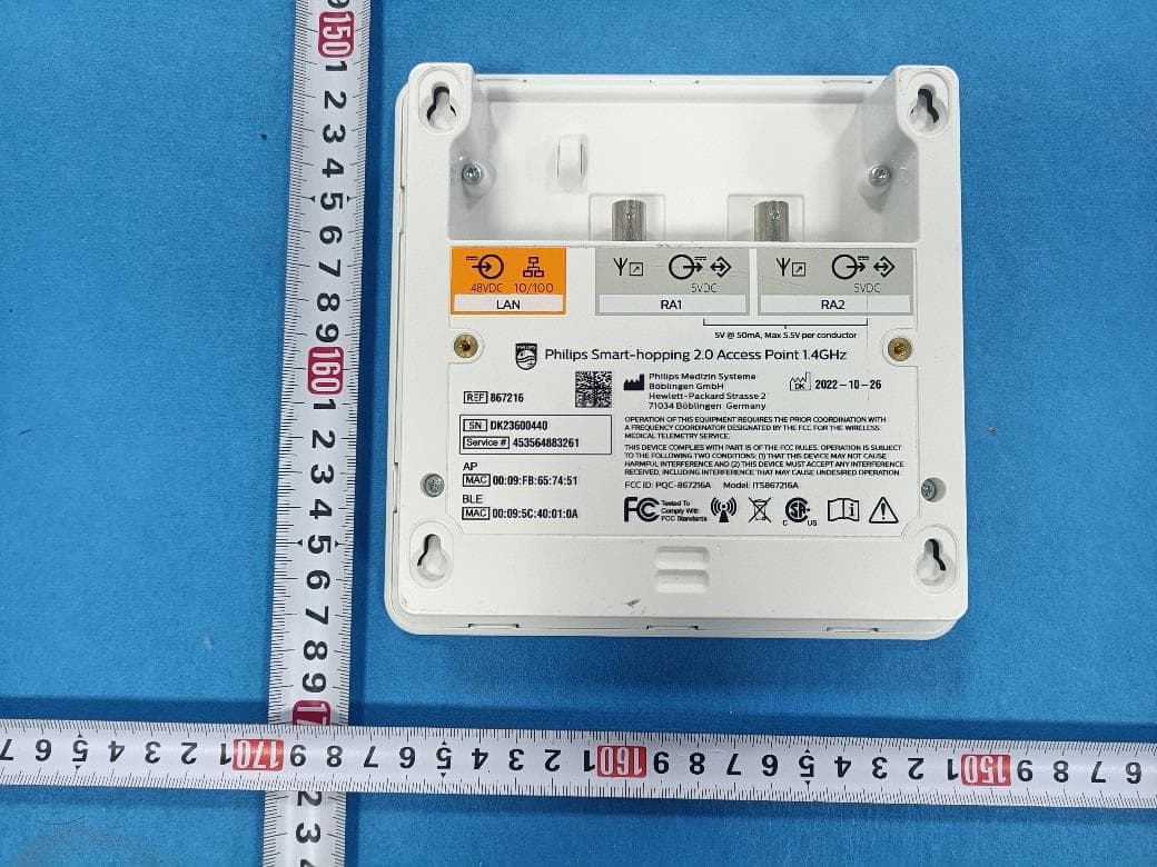
PQC-867216A
Jan 15, 2023Access Point
Equipment Class
DTS - Digital Transmission System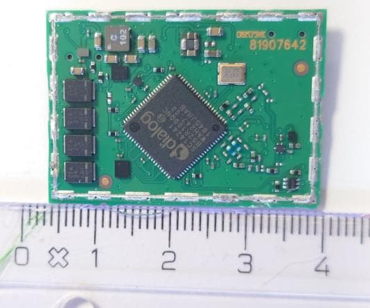
PQC-IITBV1
Mar 08, 20212.4G Radio Module
Equipment Class
DTS - Digital Transmission System
PQC-MX40SH1C4
Mar 31, 2014Intellivue MX40 1.4 GHz Patient Worn Device
Equipment Class
NII - Unlicensed National Information Infrastructure TX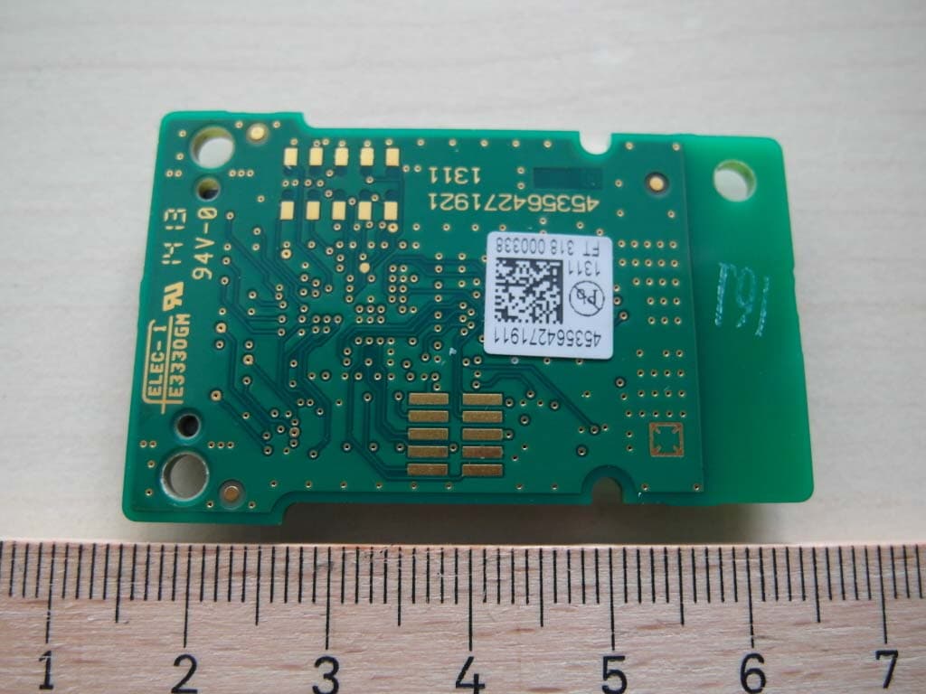
PQC-SRRBV3
Nov 17, 2013SRR Module
Equipment Class
DTS - Digital Transmission System