PQC-4852IntelliVue Access Point
Philips Medical Systems North America Co.Application Details
- Equipment Class
- DXX - Part 15 Low Power Communication Device Transmitter
- Date of Grant
- Mar 16, 2007
- Application Purpose
- Original Equipment
- Date of Application
- Nov 21, 2006
- Equipment Note
- IntelliVue Access Point
- Frequency Range
- 2401.05600000 - 2482.27200000
- Country
- United States
Documents & Files
Document Text
Text extracted from the exhibit documents filed with the FCC. Open a document above to read the original.
RF Exposure Info
RF Exposure Statement Philips Medical Systems hereby declares that the Wireless Medical Telemetry Access Point Device ITS4852A (FCC ID: PQC-4852). is compliant to 47 CFR part 15B and 15C, subpart 1.310 and subpart 2.1093 of FCC rules. The ITS4852A is an Access Point that is mounted in the ceiling or high on the walls of the hospital. As such, it is not in close proximity with users. Due to the location of the Access Point, a user will not be within 2 feet (0.609 meters) of the ITS4852A access point in normal use. Using free space propagation loss, the path loss to a use at 2 feet away is: -35.7dB, where path loss = -32.44 - 20Log(freq, MHz) + 60Log(distance, meters) The maximum ITS4852A RF radiated output power is 20dBm from the antenna (including antenna gain), so at 2 feet the amount of RF power that the user is exposed to is at worse case -15.7dBm (0.027 mW). As per the FCC/TCB training of October 15, 2004, this statement of compliance is sufficient for devices with sourced based time average power of less than 1 mW. This applies to both TCB and FCC filings. Since, the RF power that the user is exposed to with the ITS4852A is very much less than 1mW, this statement of compliance is appropriate to address RF exposure. Furthermore, the ITS4852A has a worse case duty cycle of 50%, thereby reducing the exposure level even further. Note: To reach an exposure level of 1mW the user would have to be at a distance of 4 inches from the Access Point antenna, a completely unrealistic scenario given the mounting configuration. Philips Medical Systems
Test Report
Compliance Worldwide, Inc. - 357 Main Street - Sandown, NH 03873 (603) 887 3903 Fax 887 6445 http://www.complianceworldwide.com COMPLIANCE WORLDWIDE INC. TEST REPORT 217-06R1 In Accordance with the Requirements of FCC PART 15, SUBPART C INDUSTRY CANADA RSS 210, ISSUE 6 Low Power License-Exempt Radio Communication Devices Intentional Radiators Issued to Philips Medical Systems 3000 Minuteman Drive Andover, MA 01810 978-659-2800 for ITS4852A = M4852A Telemetry II Access Point / ROW with the IntelliVue Information Center System Revision “J” Report Issued on October 25, 2006 Tested by This test report shall not be reproduced, except in full, without written permission from Compliance Worldwide, Inc. Test Number: 217-06R1 Issue Date: 10/25/2006 Page 2 of 23 Compliance Worldwide, Inc. - 357 Main Street - Sandown, NH 03873 (603) 887 3903 Fax 887 6445 http://www.cw-inc.com Table of Contents 1 Scope ................................................................................................................................... 3 2 Product Details..................................................................................................................... 3 2.1 Manufacturer............................................................................................................................ 3 2.3 Serial Number........................................................................................................................... 3 2.4 Description................................................................................................................................ 3 2.5 Power Source ........................................................................................................................... 3 2.6 EMC Modifications.................................................................................................................... 3 3 Product Configuration .......................................................................................................... 3 3.1 Operational Characteristics & Software ................................................................................... 3 3.2 Support Equipment................................................................................................................... 4 3.3 Additional Support Equipment (Directly connected to the DUT) ............................................. 4 3.4 Cables ...................................................................................................................................... 4 3.5 Block Diagram .......................................................................................................................... 5 4 Measurements Parameters.................................................................................................. 6 4.1 Measurement Equipment Used to Perform Test...................................................................... 6 4.2 Measurement & Equipment Setup ........................................................................................... 6 4.3 Test Procedure ......................................................................................................................... 6 5 Measurement Summary....................................................................................................... 7 6 Measurement Data............................................................................................................... 8 6.1 Power Line Conducted Emissions............................................................................................ 8 6.2 Radiated Field Strength of Fundamental............................................................................... 11 6.2 Radiated Field Strength of Harmonics................................................................................... 11 6.3 Spurious Radiated Emissions ................................................................................................13 6.4 Spurious Radiated Emissions >1 GHz ................................................................................... 15 6.5 Band Edge Measurements.....................................................................................................16 6.6 99% Power Bandwidth ........................................................................................................... 18 7 Test Site Description ......................................................................................................................... 19 8 Test Setup Photographs.................................................................................................................... 20 Test Number: 217-06R1 Issue Date: 10/25/2006 Page 3 of 23 Compliance Worldwide, Inc. - 357 Main Street - Sandown, NH 03873 (603) 887 3903 Fax 887 6445 http://www.cw-inc.com 1 Scope This test report certifies that the Philips ITS4852A = M4852A Telemetry II Access Point (AP)/ROW, as tested, meets the FCC Part 15, Subpart C and Industry Canada RSS 210, Issue 6 requirements. The scope of this test report is limited to the test sample provided by the client, only in as much as that sample represents other production units. If any significant changes are made to the unit, the changes shall be evaluated and a retest may be required. This report replaces test report# 217-06. 2 Product Details 2.1 Manufacturer: Philips Medical Systems 2.2 Model Number: ITS4852A = M4852A Telemetry II Access Point / ROW 2.3 Serial Number: US42300589 2.4 Description: ITS4852A = M4852A Access Point receives the telemetry signal from the Patient Worn Device and sends patient data to the IntelliVue Information Center through the current CTS Infrastructure via the M3185A IntelliVue Clinical Network. 2.5 Power Source: 48 Volts DC through Ethernet cable 2.6 EMC Modifications: None 3 Product Configuration 3.1 Operational Characteristics & Software 3.3.1 From APC Web interface, a) Go to ‘WMTS AP Configuration’ screen, b) Select ‘ISM AREA’ pull down …
Text truncated - open the document above for the full version.
Contact Information
Applicant
Delroy Smith(Principal Architect)
Technical Contact
Philips Medical SystemsBarry Wyshogrod
[email protected]978-659-7383
3000 Minuteman Road · Andover, Massachusetts · United States
Non-Technical Contact
Philips Medical SystemsBarry Wyshogrod
[email protected]978-659-7383
Test Firm
Compliance Worldwide, Inc.Larry Stillings
Technical Specifications
| # | Rule Parts | Frequency Range | Power Output |
|---|---|---|---|
| 1 | 15C | 2.40 GHz - 2.48 GHz | - |
Other Applications from Philips Medical Systems North America Co.
PQC-AIM
Apr 14, 2024AIM
Equipment Class
DTS - Digital Transmission System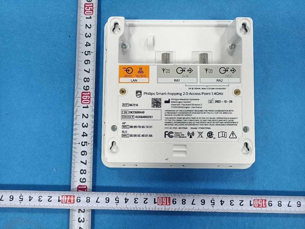
PQC-867216A
Jan 15, 2023Access Point
Equipment Class
DTS - Digital Transmission System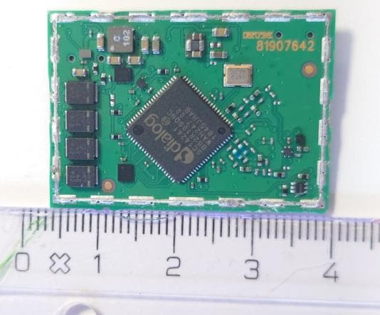
PQC-IITBV1
Mar 08, 20212.4G Radio Module
Equipment Class
DTS - Digital Transmission System
PQC-MX40SH1C4
Mar 31, 2014Intellivue MX40 1.4 GHz Patient Worn Device
Equipment Class
NII - Unlicensed National Information Infrastructure TX
PQC-OBRBSBV1
Nov 17, 2013CTG Base Station
Equipment Class
TNB - Licensed Non-Broadcast Station Transmitter