PQC-SRRBV3SRR Module
Philips Medical Systems North America Co.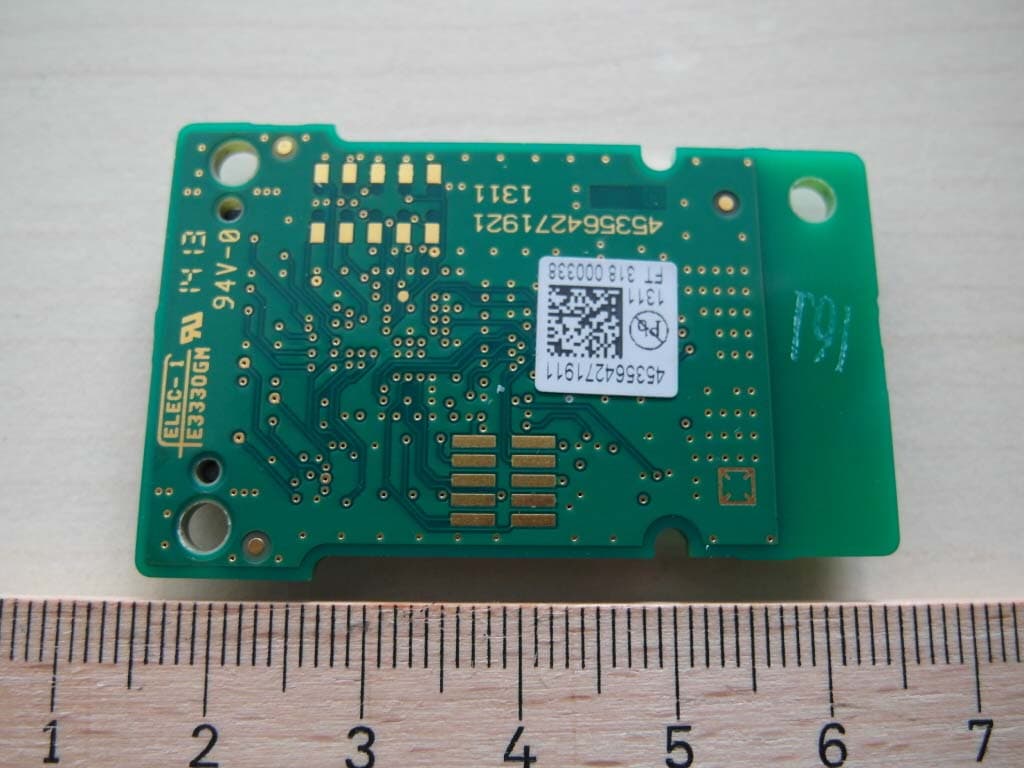
Click to zoom
Application Details
- Equipment Class
- DTS - Digital Transmission System
- Date of Grant
- Nov 17, 2013
- Application Purpose
- Original Equipment
- Date of Application
- Nov 17, 2013
- Equipment Note
- SRR Module
- Frequency Range
- 2405.00000000 - 2480.00000000
- Country
- United States
Documents & Files
Document Text
Text extracted from the exhibit documents filed with the FCC. Open a document above to read the original.
Users Manual
Instructions for Use IntelliVue Patient Monitor MX400/450/500/550/600/700/800 MX400/450/500/550 Release K with Rev. K.1x.xx MX600/700/800 Release J with Revison J.xx.xx Patient Monitoring 3 1Table of Contents 1Introduction13 Safety Information14 Security Information15 Introducing the Monitor16 Devices for Acquiring Measurements18 Operating and Navigating27 Operating Modes36 Understanding Screens37 Connecting Additional Displays to the Monitor38 Using the XDS Remote Display39 Using the Visitor Screen39 Understanding Profiles39 Understanding Settings41 Changing Wave Speeds42 Freezing Waves42 Using Labels44 Entering Measurements Manually46 Changing Monitor Settings47 Checking Your Monitor Revision48 Getting Started48 Disconnecting from Power49 Networked Monitoring50 Using the Integrated PC50 Using Your Monitor with a Monitor in Companion Mode52 2What's New?55 What's New in Release K.1 (for MX400/450/500/550 only)55 What's New in Release K.055 What's New in Release J.056 3Alarms59 Visual Alarm Indicators60 Audible Alarm Indicators61 Acknowledging Alarms63 Pausing or Switching Off Alarms64 Alarm Limits67 Reviewing Alarms71 Latching Alarms72 Testing Alar ms73 Alarm Behavior at Power On73 4 Alarm Recordings73 4Patient Alarms and INOPs75 Patient Alarm Messages75 Technical Alarm Messages (INOPs)81 5Managing Patients and Equipment105 Patient Concepts105 Equipment Concepts105 Managing Patients106 Managing Equipment119 Care Groups126 Information Center Compatibility132 6ECG, Arrhythmia, ST and QT Monitoring133 Skin Preparation for Electrode Placement133 Connecting ECG Cables133 Selecting the Primary and Secondary ECG Leads134 Checking Paced Mode134 Understanding the ECG Display134 Monitoring Paced Patients135 Changing the Size of the ECG Wave136 Changing the Volume of the QRS Tone137 Changing the ECG Filter Settings137 Selecting Positions of Va and Vb Chest Leads (for 6-lead placement)138 Choosing EASI or Standard Lead Placement138 About ECG Leads138 ECG Lead Fallback139 ECG Lead Placements139 EASI ECG Lead Placement145 Capture 12-Lead146 ECG and Arrhythmia Alarm Overview149 Using ECG Alarms151 ECG Safety Information152 About Arrhythmia Monitoring154 Switching Arrhythmia Analysis On and Off154 Choosing an ECG Lead for Arrhythmia Monitoring155 Atrial Fibrillation Alarm155 Aberrantly-Conducted Beats156 Intermittent Bundle Branch Block156 Understanding the Arrhythmia Display156 Arrhythmia Relearning159 Arrhythmia Alarms160 About ST Monitoring164 Switching ST or STE On and Off165 Understanding the ST Display166 5 Updating ST Baseline Snippets168 Recording ST Segments168 About the ST Measurement Points168 ST Alarms171 STE Alarms171 Viewing ST Maps172 About QT/QTc Interval Monitoring175 QT Alarms178 Switching QT Monitoring On and Off179 7Monitoring Pulse Rate181 Entering the Setup Pulse Menu181 System Pulse Source181 Switching Pulse On and Off182 Using Pulse Alarms182 8Monitoring Respiration Rate (Resp)185 Lead Placement for Monitoring Resp185 Understanding the Resp Display186 Changing Resp Detection Modes186 Changing the Size of the Respiration Wave187 Changing the Speed of the Respiration Wave188 Using Resp Alarms188 Changing the Apnea Alarm Delay188 Resp Safety Information188 9Monitoring SpO2191 SpO2 Sensors191 Applying the Sensor191 Connecting SpO2 Cables192 Measuring SpO2192 SpO2 Signal Quality Indicator (FAST SpO2 only)193 Assessing a Suspicious SpO2 Reading194 Changing the Averaging Time194 Understanding SpO2 Alarms194 Pleth Wave200 Perfusion Numeric200 Perfusion Change Indicator200 Setting SpO2/Pleth as Pulse Source200 Setting Up Tone Modulation201 Setting the QRS Volume201 Calculating SpO2 Difference201 10Monitoring NBP203 Introducing the Oscillometric NBP Measurement203 Preparing to Measure NBP205 6 Starting and Stopping Measurements207 Enabling Automatic Mode and Setting Repetition Time208 Enabling Sequence Mode and Setting Up The Sequence208 Choosing the NBP Alarm Source209 Switching Pulse from NBP On/Off209 Assisting Venous Puncture210 Calibrating NBP210 11Monitoring Temperature211 Making a Temp Measurement211 Calculating Temp Difference212 12Monitoring Invasive Pressure213 Setting up the Pressure Measurement213 Zeroing the Pressure Transducer215 Adjusting the Calibration Factor217 Displaying a Mean Pressure Value Only217 Changing the Pressure Wave Scale217 Optimizing the Waveform217 Using the Wave Cursor217 Non-Physiological Artifact Suppression218 Choosing the Pressure Alarm Source218 Calibrating Reusable Transducer CPJ840J6219 Calculating Cerebral Perfusion Pressure221 Calculating Pulse Pressure Variation221 Measuring IAP222 Measuring Pulmonary Artery Wedge Pressure222 Editing the Wedge223 Identifying the Pressure Analog Output Connector224 13Monitoring Cardiac Output225 Hemodynamic Parameters226 Using the C.O. Procedure Window226 Accessing the Setup C.O. and Setup CCO Menus228 Entering the HemoCalc Window228 Measuring C. O. Using the PiCCO Method228 Measuring C.O. Using the Right Heart Thermodilution Method233 Documenting C.O. Measurements235 C.O. Injectate Guidelines235 C.O./CCO Curve Alert Messages236 C.O./CCO Prompt Messages238 C.O./CCO Warning Messages238 C.O./CCO Safety Information239 14Monitoring Carbon Dioxide241 Measurement Principles242 7 Measuring CO2 using M3014A or X2242 Measuring Mainstream CO2 using M3016A246 Measuring Microstream CO2 using M3015A/B248 Setting up all CO2 Measurements250 Understanding the IPI Numeric252 15Monitoring Airway Flow, Volume and Pressure255 Attaching the Flow Sensor256 Zero Calibration258 Automatic Purging258 Manual Purging259 Gas Compensation259 Setting up Spirometry260 16Monitoring tcGas263 Identifying tcGas Module Components263 Setting the tcGas Sensor Temperature264 Using the tcGas Site Timer264 Setting the tcGas Barometric Pressure265 Remembraning the tcGas Transducer265 Calibrating the tcGas Transducer265 Applying the tcGas Transducer267 Finishing tcGas Monitoring268 Zeroing the tcGas Relative Heat Power268 TcGas Corrections268 17Monitoring I…
Text truncated - open the document above for the full version.
External Photos
Test report no.: 1-5420/12-01-01_AnnexA 2013-09-18 Page 1 of 3 Annex A This test report annex is electronically signed and valid without handwriting signature. For verification of the electronic signatures, the public keys can be requested at the testing laboratory. Test report annex authorised: Christoph Schneider Expert Test report no.: 1-5420/12-01-01_AnnexA 2013-09-18 Page 2 of 3 External photos of the EUT Photo documentation: Photo 1: Photo 2: Test report no.: 1-5420/12-01-01_AnnexA 2013-09-18 Page 3 of 3 Document history Version Applied changes Date of release 1.0 Initial release 2013-09-06
Internal Photos
Test report no.: 1-5420/12-01-01_AnnexB 2013-09-18 Page 1 of 3 Annex B This test report annex is electronically signed and valid without handwriting signature. For verification of the electronic signatures, the public keys can be requested at the testing laboratory. Test report annex authorised: Christoph Schneider Expert Test report no.: 1-5420/12-01-01_AnnexB 2013-09-18 Page 2 of 3 External photos of the EUT Photo documentation: Photo 1: Photo 2: Test report no.: 1-5420/12-01-01_AnnexB 2013-09-18 Page 3 of 3 Document history Version Applied changes Date of release 1.0 Initial release 2013-09-06
Test Report
2013-09-18 Page 1 of 52 TEST REPORT Test report no.: 1-5420/12-01-11 Testing laboratory Applicant CETECOM ICT Services GmbH Untertuerkheimer Strasse 6 – 10 66117 Saarbruecken / Germany Phone: + 49 681 5 98 - 0 Fax: + 49 681 5 98 - 9075 Internet: http://www.cetecom.com e-mail: [email protected] Accredited Testing Laboratory: The testing laboratory (area of testing) is accredited according to DIN EN ISO/IEC 17025 (2005) by the Deutsche Akkreditierungsstelle GmbH (DAkkS) The accreditation is valid for the scope of testing procedures as stated in the accreditation certificate with the registration number: D-PL-12076-01-01 Area of Testing: Radio/Satellite Communications Philips Medizin Systeme Böblingen GmbH Hewlett-Packard-Strasse 2 71034 Böblingen / GERMANY Phone: -/- Fax: +49 7031 463-2442 Contact: Markus Stacha e-mail: [email protected] Phone: +49 7031 463-2840 Manufacturer Philips Medizin Systeme Böblingen GmbH Hewlett-Packard-Strasse 2 71034 Böblingen / GERMANY Test standard/s 47 CFR Part 15 Title 47 of the Code of Federal Regulations; Chapter I Part 15 - Radio frequency devices RSS - 210 Issue 8 Spectrum Management and Telecommunications - Radio Standards Specification Low-power Licence-exempt Radiocommunication Devices (All Frequency Bands): Category I Equipment For further applied test standards please refer to section 3 of this test report. Test Item Kind of test item: 2.4 GHz Transceiver Model name: SRR Module BV3 FCC ID: PQC-SRRBV3 IC: 3549C-SRRBV3 Frequency: ISM band 2400 MHz to 2483.5 MHz (lowest channel 11 – 2405 MHz; highest channel 26 – 2480 MHz) Technology tested: proprietary Antenna: Integrated antenna Power supply: 5 V DC, USB powered Temperature range: -20°C to +55°C This test report is electronically signed and valid without handwriting signature. For verification of the electronic signatures, the public keys can be requested at the testing laboratory. Test report authorised: Test performed: Marco Bertolino Christoph Schneider Testing Manager Expert Test report no.: 1-5420/12-01-11 2013-09-18 Page 2 of 52 1 Table of contents 1 Table of contents ............................................................................................................................................ 2 2 General information ....................................................................................................................................... 3 2.1 Notes and disclaimer .......................................................................................................................... 3 2.2 Application details ............................................................................................................................... 3 3 Test standard/s ............................................................................................................................................... 3 4 Test environment ............................................................................................................................................ 4 5 Test item .......................................................................................................................................................... 4 5.1 Additional information ........................................................................................................................ 4 6 Test laboratories sub-contracted ................................................................................................................. 4 7 Summary of measurement results ............................................................................................................... 5 8 RF measurements .......................................................................................................................................... 6 8.1 Description of test setup .................................................................................................................... 6 8.1.1 Radiated measurements............................................................................................................. 6 8.1.2 Conducted measurements.......................................................................................................... 7 8.2 Additional comments .......................................................................................................................... 7 8.3 RSP100 test report cover sheet / performance test data ................................................................ 8 9 Measurement results ...................................................................................................................................... 9 9.1 Antenna gain ........................................................................................................................................ 9 9.2 Maximum output power .................................................................................................................... 10 9.3 Power spectral density ..................................................................................................................... 13 9.4 Spectrum bandwidth – 6 dB bandwidth .......................................................................................... 16 9.5 Spectrum bandwidth – 99% emission bandwidth .......................................................................... 19 9.6 Band edge compliance conducted .................................................................................................. 22 9.7 Band edge compliance radiated ...................................................................................................... 24 9.8 TX spurious emissions conducted .................................................................................................. 27 9.9 TX spurious emissions radiated ...................................................................................................... 31 9.10 RX spurious emissions radiated ...........................…
Text truncated - open the document above for the full version.
Test Setup Photos
Test report no.: 1-5420/12-01-01_AnnexD 2013-09-18 Page 1 of 5 Annex D This test report annex is electronically signed and valid without handwriting signature. For verification of the electronic signatures, the public keys can be requested at the testing laboratory. Test report annex authorised: Christoph Schneider Expert Test report no.: 1-5420/12-01-01_AnnexD 2013-09-18 Page 2 of 5 Test setup photos Photo documentation: Photo 1: Photo 2: Test report no.: 1-5420/12-01-01_AnnexD 2013-09-18 Page 3 of 5 Photo 3: Photo 4: Test report no.: 1-5420/12-01-01_AnnexD 2013-09-18 Page 4 of 5 Photo 5: Photo 6: Test report no.: 1-5420/12-01-01_AnnexD 2013-09-18 Page 5 of 5 Document history Version Applied changes Date of release 1.0 Initial release 2013-09-06
Contact Information
Applicant
Delroy Smith(Principal Architect)
Test Firm
cetecom advanced GmbHGerald Schmidt
Technical Specifications
| # | Rule Parts | Frequency Range | Power Output |
|---|---|---|---|
| 1 | 15C | 2.40 GHz - 2.48 GHz | 5.80 mW |
Other Applications from Philips Medical Systems North America Co.
PQC-AIM
Apr 14, 2024AIM
Equipment Class
DTS - Digital Transmission System
PQC-867216A
Jan 15, 2023Access Point
Equipment Class
DTS - Digital Transmission System
PQC-IITBV1
Mar 08, 20212.4G Radio Module
Equipment Class
DTS - Digital Transmission System
PQC-MX40SH1C4
Mar 31, 2014Intellivue MX40 1.4 GHz Patient Worn Device
Equipment Class
NII - Unlicensed National Information Infrastructure TX
PQC-OBRBSBV1
Nov 17, 2013CTG Base Station
Equipment Class
TNB - Licensed Non-Broadcast Station Transmitter