PQC-MX40WLAN2Intellivue MX40 WLAN2 Patient Worn Device
Philips Medical Systems North America Co.
Click to zoom
Application Details
- Equipment Class
- DTS - Digital Transmission System
- Date of Grant
- Apr 29, 2012
- Application Purpose
- Original Equipment
- Date of Application
- Apr 29, 2012
- Equipment Note
- Intellivue MX40 WLAN2 Patient Worn Device
- Frequency Range
- 2405.00000000 - 2480.00000000
- Country
- United States
Documents & Files
Document Text
Text extracted from the exhibit documents filed with the FCC. Open a document above to read the original.
Users Manual
IntelliVue MX40 Instructions for Use Release B.0 Draft Copy ii Notice Proprietary Information This document contains proprietary information, which is protected by copyright. First Edition 2012 4535 643 15721 Copyright Copyright © 2012 Koninklijke Philips Electronics N.V. All rights reserved. Reproduction in whole or in part is prohibited without the prior written consent of the copyright holder. Philips Medical Systems Nederland B.V. reserves the right to make changes in specifications and/or to discontinue any products at any time without notice or obligation and will not be liable for any consequences resulting from the use of this publication. This product contains software licensed under an open source license. For acknowledgments, license texts and source code, please refer to the IntelliVue Information Center iX M3290B Software\References\README.pdf. Windows ® is a registered trademark of Microsoft Corporation in the United States and other countries. EASI is a trademark of Zymed Inc. OxiCliq ® and OxiMax ® are registered trademarks of Nellcor Incorporated. Duracell ® is a registered trademark of Procter & Gamble Incorporated. STERRAD ® is a registered trademark of Advanced Sterilization Products. GORE-TEX ® is a registered trademark of W.L. Gore & Assoc. Incorporated. Tone modulation is licensed under US patent 4,653,498 from Nellcor Puritan Bennett Incorporated. Manufacturer Philips Medical Systems 3000 Minuteman Road Andover, MA 01810-1099 (978) 687-1501 Printed in USA Document number Draft Copy iii 4535 643 15721 Warranty The information contained in this document is subject to change without notice. Philips Medical Systems makes no warranty of any kind with regard to this material, including, but not limited to, the implied warranties or merchantability and fitness for a particular purpose. Philips Medical Systems shall not be liable for errors contained herein or for incidental or consequential damages in connection with the furnishing, performance, or use of this material. FCC This device complies with Part 15 and/or Part 95 of the FCC Rules. Operation is subject to the following two conditions: (1) these devices may not cause harmful interference, and (2) these devices must accept any interference received, including interference that may cause undesired operation. Changes and modifications not expressly approved by Philips Medical Systems can void your authority to operate this equipment under Federal Communications Commission's rules Protecting Personal Information It is recommended that customers have policies and procedures for the proper handling of personal or sensitive information, ePHI (electronic protected health information) and PHI (protected health information), which will maintain the confidentiality, integrity, and the availability of these types of data. Any organization using this product should implement the required protective means necessary to safeguard personal information consistent with each applicable country law, code and regulation; and consistent with their developed and maintained internal policies and procedures. While handling personal information is outside the scope of this document; in general, each organization is responsible for identifying: Who has access to personal data and under what conditions an individual has authorization to use that data. What security controls are in place to protect personal and sensitive data. How the data is stored and the conditions by which it is stored. How the data is transmitted and the conditions under which that data is transmitted. Draft Copy iv Protecting personal health information is a primary component of a security strategy. Personal and sensitive information should be protected according to the applicable laws, regulations and directives, such as HIPAA, PIPEDA and/or Council of the European Union security and privacy rules. Compliance Uses of the system for purposes other than those intended and expressly stated by the manufacturer, as well as incorrect use, incorrect operation, or modifications made to the system without explicit approval from Philips, may relieve the manufacturer (or his agent) from all or some responsibilities for resultant noncompliance, damage or injury. Printing History New editions of this document will incorporate all material updated since the previous edition. Update packages may be issued between editions and contain replacement and additional pages to be merged by a revision date at the bottom of the page. Note that pages which are rearranged due to changes on a previous page are not considered revised. The documentation printing date and part number indicate its current edition. The printing date changes when a new edition is printed. (Minor corrections and updates which are incorporated at reprint do not cause the date to change.) The document part number changes when extensive technical changes are incorporated. First Edition February 2012 Document Conventions In this guide: Warnings Warning A Warning alerts you to a potential serious outcome, adverse event or safety hazard. Failure to observe a warning may result in death or serious injury to the user or patient. Draft Copy v Cautions Caution A Caution alerts you to where special care is necessary for the safe and effective use of the product. Failure to observe a caution may result in minor or moderate personal injury or damage to the product or other property, and possibly in a remote risk of more serious injury. Notes A Note contains additional information on the product's usage. Draft Copy vi Draft Copy Contents 1 Contents 1. Introducing the IntelliVue MX40 1-1 MX40 Features -------------------------------------------------------------------------- 1-2 MX40 Models ---------------------------------------------------------------------------- 1-3 MX40 Release B.0 Compatibility --------------------------------------------------- 1-4 2. What's New? 2-1 New Features and Enhancements---------------------------------…
Text truncated - open the document above for the full version.
Cover Letter(s)
Compliance Worldwide, Inc. - 357 Main Street - Sandown, NH 03873 (603) 887 3903 Fax (603) 887 6445 www.complianceworldwide.com April 23, 2012 RE: Philips Medical Systems MX40 Patient Worn Monitor FCC ID: PQC-MX40WLAN2 IC: 3549B-MX40WLAN2 To whom it may concern: Please find enclosed an original application for Philips Medical Systems, Philips Telemetry System MX40 Patient Worn Monitor. This device was previously approved under FCC ID: PQC- MX40WLAN and IC: 3549B-MX40WLAN by TIMCO Engineering in August 2011. These approval ids consisted of a review of a 2.4 GHz WLAN 802.11 radio CW Test Report #304- 11R2 and 2.4 GHz Short Range Radio (SRR) under CW Test Report #264-11R1. This application includes data and information for the enabling of a 5 GHz WiFi WLAN Radio within the device along with an updated set of data for the 2.4 GHz 802.11 WiFi WLAN Radio and the original 2.4 GHz SRR Radio. This was achieved via a software change, and none of the hardware has changed since the original application. Since the power of the radio has increased in the 5 GHz band vs. what was originally reported in the 2.4 GHz band, a class II permissive change could not be performed. Although the reported power of the device in the 2.4 GHz and 5.8 GHz ranges exceeds the public exposure limits for a portable device, the source-based time averaged power is significantly below the limits. The only purpose of any of the radios in the device is to transmit telemetry data collected by the device back to either a central station or a bedside monitor. As shown in the timing plots of either the 2.4 or 5 GHz WLAN radios a very short transmission burst (less than 400 microseconds) is sent only once in a 100 mS period. An updated MPE Calculation for all the radios has been provided as part of this application. If you have any further questions, please don’t hesitate to contact me at (603) 887 3903 or via email at [email protected] Sincerely, Larry Stillings President
External Photos
External Photos, MX40, FCC ID: PQC-MX40WLAN2 Front Back
Internal Photos
Internal Photos, MX40, FCC ID: PQC-MX40WLAN2 Component side: SpO2 board Solder Side: SpO2 board Main board Main board with SRR and WLAN SRR and WLAN Module
RF Exposure Info
Test Set Up (MX40-WL2) Radiated Emissions Front Radiated Emissions Rear
Test Report
Compliance Worldwide, Inc. - 357 Main Street - Sandown, NH 03873 COMPLIANCE WORLDWIDE INC. TEST REPORT 264-11R2 In Accordance with the Requirements of FCC PART 15.247, SUBPART C INDUSTRY CANADA RSS 210, ISSUE 8 Low Power License-Exempt Radio Communication Devices Intentional Radiators Issued to Philips Medical Systems 3000 Minuteman Drive Andover, MA 01810 978-659-2800 for the Philips Telemetry System MX40 Patient Worn Monitor 2.4 GHz Short Range Radio (SRR) FCC ID: PQC-MX40WLAN2 IC: 3549B-MX40WLAN2 Report Issued on April 23, 2012 Tested by This test report shall not be reproduced, except in full, without written permission from Compliance Worldwide, Inc. (603) 887 3903 Fax 887 6445 http://www.complianceworldwide.com Test Number: 264-11R2 Issue Date: 04/23/2012 Page 2 of 30 Compliance Worldwide, Inc. - 357 Main Street - Sandown, NH 03873 (603) 887 3903 Fax 887 6445 http://www.cw-inc.com Table of Contents 1. Scope .................................................................................................................................. 3 2 .Product Details.................................................................................................................... 3 2.1 Manufacturer ............................................................................................................................ 3 2.3 Serial Number........................................................................................................................... 3 2.4 Description................................................................................................................................ 3 2.5 Power Source ........................................................................................................................... 3 2.6 EMC Modifications.................................................................................................................... 3 3. Product Configuration ......................................................................................................... 3 3.1 Operational Characteristics & Software ................................................................................... 3 3.2 EUT Hardware.......................................................................................................................... 4 3.3 . EUT Hardware/Software/Firmware Revision Level................................................................ 4 3.4 EUT Cables/Transducers ......................................................................................................... 4 3.5 Support Equipment................................................................................................................... 4 3.6 Support Equipment Cables/Transducers ................................................................................. 4 3.7 Miscellaneous........................................................................................................................... 4 3.7 Block Diagram .......................................................................................................................... 5 4. Measurements Parameters.................................................................................................6 4.1 Measurement Equipment Used to Perform Test...................................................................... 6 4.2 Measurement & Equipment Setup ........................................................................................... 6 4.3 Measurement Procedure .......................................................................................................... 6 5. Choice of Equipment for Test Suits..................................................................................... 7 5.1 Choice of Model........................................................................................................................ 7 5.2 Presentation ............................................................................................................................. 7 5.3 Choice of Operating Frequencies.............................................................................................7 6. Measurement Summary......................................................................................................8 7. Measurement Data.............................................................................................................. 8 7.1 Antenna Requirement .............................................................................................................. 8 7.2 Minimum 6 dB Bandwidth......................................................................................................... 8 7.3 99% Bandwidth....................................................................................................................... 11 7.4 Maximum Peak Conducted Output Power ............................................................................. 13 7.5 Operation with directional antenna gains greater than 6 dBi ................................................. 16 7.6 Transmitter Spurious Radiated Emissions ............................................................................. 16 7.7 Receiver Spurious Radiated Emissions ................................................................................. 19 7.8 Band Edge Measurements.....................................................................................................22 7.9 Power Spectral Density .......................................................................................................... 25 7.10 Public Exposure to Radio Frequency Energy Levels ........................................................... 27 8. Test Setup Photographs.............................................................................................................. 28 9. Test Site Description..................................................................................................................... 30 Test N…
Text truncated - open the document above for the full version.
Test Report
Compliance Worldwide, Inc. - 357 Main Street - Sandown, NH 03873 COMPLIANCE WORLDWIDE INC. TEST REPORT 141-12R1 In Accordance with the Requirements of FCC PART 15.247, SUBPART C INDUSTRY CANADA RSS 210, ISSUE 8, Annex 8 Low Power License-Exempt Radio Communication Devices Intentional Radiators Issued to Philips Medical Systems 3000 Minuteman Drive Andover, MA 01810 978-659-2800 for the Philips Telemetry System MX40 Patient Worn Monitor WLAN Radio FCC ID: PQC-MX40WLAN2 IC: 3549B-MX40WLAN2 Original Report Issued on April 23, 2012 Tested by This test report shall not be reproduced, except in full, without written permission from Compliance Worldwide, Inc. (603) 887 3903 Fax 887 6445 http://www.complianceworldwide.com Test Number: 141-12R1 Issue Date: 04/23/2012 Page 2 of 36 Compliance Worldwide, Inc. - 357 Main Street - Sandown, NH 03873 (603) 887 3903 Fax 887 6445 http://www.cw-inc.com Table of Contents 1. Scope .................................................................................................................................. 3 2 .Product Details.................................................................................................................... 3 2.1 Manufacturer ............................................................................................................................ 3 2.3 Serial Number........................................................................................................................... 3 2.4 Description................................................................................................................................ 3 2.5 Power Source ........................................................................................................................... 3 2.6 EMC Modifications.................................................................................................................... 3 3. Product Configuration ......................................................................................................... 4 3.1 Operational Characteristics & Software ................................................................................... 4 3.2 EUT Hardware.......................................................................................................................... 4 3.3 EUT Hardware/Software/Firmware Revision Level.................................................................. 4 3.4 EUT Cables/Transducers ......................................................................................................... 4 3.5 Support Equipment................................................................................................................... 4 3.6 Support Equipment Cables/Transducers ................................................................................. 5 3.7 Miscellaneous........................................................................................................................... 5 3.8 Block Diagram .......................................................................................................................... 5 4. Measurements Parameters.................................................................................................6 4.1 Measurement Equipment Used to Perform Test...................................................................... 6 4.2 Measurement & Equipment Setup ........................................................................................... 6 4.3 Measurement Procedure .......................................................................................................... 6 4.4 Measurement Uncertainty ........................................................................................................ 7 5. Choice of Equipment for Test Suits..................................................................................... 7 5.1 Choice of Model........................................................................................................................ 7 5.2 Presentation ............................................................................................................................. 7 5.3 Choice of Operating Frequencies.............................................................................................7 6. Measurement Summary......................................................................................................8 7. Measurement Data.............................................................................................................. 9 7.1 Antenna Requirement .............................................................................................................. 9 7.2 Minimum 6 dB Bandwidth......................................................................................................... 9 7.3 99% Bandwidth....................................................................................................................... 11 7.4 Maximum Peak Conducted Output Power ............................................................................. 14 7.5 Operation with directional antenna gains greater than 6 dBi ................................................. 16 7.6 Transmitter Spurious Radiated Emissions ............................................................................. 17 7.7 Receiver Spurious Radiated Emissions ................................................................................. 22 7.8 Band Edge Measurements.....................................................................................................25 7.9 Power Spectral Density .......................................................................................................... 28 7.10 Public Exposure to Radio Frequency Energy Levels ........................................................... 31 8. Test Setup Photographs.............................................................................................................. 34 9. Test Site Descri…
Text truncated - open the document above for the full version.
Test Setup Photos
Test Set Up (MX40-WL2) Radiated Emissions Front Radiated Emissions Rear
Contact Information
Applicant
Delroy Smith(Principal Architect)
Test Firm
Compliance Worldwide, Inc.Larry Stillings
Technical Specifications
| # | Rule Parts | Frequency Range | Power Output |
|---|---|---|---|
| 2 | 15C | 2.40 GHz - 2.48 GHz | 600.00 µW |
Other Applications from Philips Medical Systems North America Co.
PQC-AIM
Apr 14, 2024AIM
Equipment Class
DTS - Digital Transmission System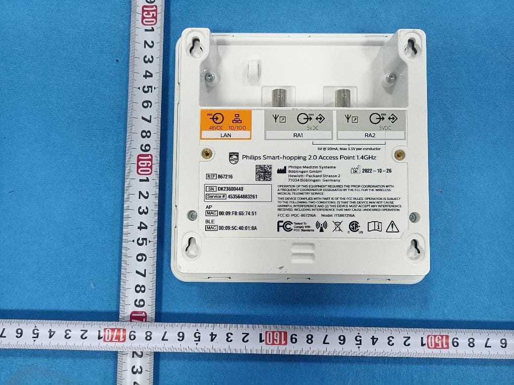
PQC-867216A
Jan 15, 2023Access Point
Equipment Class
DTS - Digital Transmission System
PQC-IITBV1
Mar 08, 20212.4G Radio Module
Equipment Class
DTS - Digital Transmission System
PQC-MX40SH1C4
Mar 31, 2014Intellivue MX40 1.4 GHz Patient Worn Device
Equipment Class
NII - Unlicensed National Information Infrastructure TX
PQC-OBRBSBV1
Nov 17, 2013CTG Base Station
Equipment Class
TNB - Licensed Non-Broadcast Station Transmitter