PQC-SRRBV2Single Short Range Radio Module
Philips Medical Systems North America Co.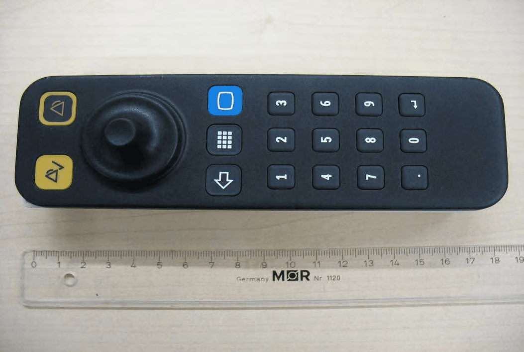
Click to zoom
Application Details
- Equipment Class
- DTS - Digital Transmission System
- Date of Grant
- Sep 09, 2010
- Application Purpose
- Original Equipment
- Date of Application
- Sep 09, 2010
- Equipment Note
- Single Short Range Radio Module
- Frequency Range
- 2405.00000000 - 2480.00000000
- Country
- United States
Documents & Files
Document Text
Text extracted from the exhibit documents filed with the FCC. Open a document above to read the original.
Users Manual
Instructions for Use IntelliVue Patient Monitor MX800 Release H.0 with Software Revision H.0x.xx Patient Monitoring Draft Part Number 453564208131 Printed in Germany 07/10 *453564208131* 3 1Table of Contents 1Introduction13 Introducing the Monitor13 Devices for Acquiring Measurements14 Operating and Navigating22 Operating Modes29 Understanding Screens31 Connecting Additional Displays to the Monitor32 Using the XDS Remote Display32 Using the Visitor Screen33 Understanding Profiles33 Understanding Settings34 Changing Wave Speeds36 Freezing Waves36 Entering Measurements Manually40 Changing Monitor Settings41 Checking Your Monitor Revision42 Getting Started42 Disconnecting from Power43 Networked Monitoring44 Using the Integrated PC44 Using the X2 or MP5 with a Host Monitor46 2Alarms47 Visual Alarm Indicators48 Audible Alarm Indicators49 Acknowledging Alarms51 Pausing or Switching Off Alarms52 Alarm Limits54 Reviewing Alarms58 Latching Alarms59 Testing Alar ms60 Alarm Behavior at Power On60 Alarm Recordings61 3Patient Alarms and INOPs63 Patient Alarm Messages63 Technical Alarm Messages (INOPs)68 4Managing Patients93 Admitting a Patient93 4 Quick Admitting a Patient94 Editing Patient Information95 Discharging a Patient95 Transferring Patients96 Data Upload from an MMS100 Care Groups103 5ECG, Arrhythmia, ST and QT Monitoring109 Skin Preparation for Electrode Placement109 Connecting ECG Cables109 Selecting the Primary and Secondary ECG Leads110 Checking Paced Status110 Understanding the ECG Display110 Monitoring Paced Patients111 Changing the Size of the ECG Wave112 Changing the Volume of the QRS Tone113 Changing the ECG Filter Settings113 Selecting Positions of Va and Vb Chest Leads (for 6-lead placement)114 Choosing EASI or Standard Lead Placement114 About ECG Leads114 ECG Lead Fallback115 ECG Lead Placements115 Capture 12-Lead121 EASI ECG Lead Placement123 ECG and Arrhythmia Alarm Overview124 Using ECG Alarms125 ECG Safety Information126 About Arrhythmia Monitoring127 Switching Arrhythmia Analysis On and Off128 Choosing an ECG Lead for Arrhythmia Monitoring128 Understanding the Arrhythmia Display130 Arrhythmia Relearning132 Arrhythmia Alarms133 About ST Monitoring137 Switching ST On and Off138 Understanding the ST Display139 Updating ST Baseline Snippets140 Recording ST Segments140 About the ST Measurement Points141 ST Alarms143 Viewing ST Maps144 About QT/QTc Interval Monitoring147 QT Alarms150 Switching QT Monitoring On and Off151 5 6Monitoring Pulse Rate153 Entering the Setup Pulse Menu153 System Pulse Source153 Switching Pulse On and Off154 Using Pulse Alarms154 7Monitoring Respiration Rate (Resp)157 Lead Placement for Monitoring Resp157 Understanding the Resp Display158 Changing Resp Detection Modes158 Changing the Size of the Respiration Wave159 Changing the Speed of the Respiration Wave160 Using Resp Alarms160 Changing the Apnea Alarm Delay160 Resp Safety Information160 8Monitoring SpO2163 SpO2 Sensors163 Applying the Sensor163 Connecting SpO2 Cables164 Measuring SpO2165 SpO2 Signal Quality Indicator (Fast SpO2 only)165 Assessing a Suspicious SpO2 Reading166 Changing the Averaging Time166 Understanding SpO2 Alarms166 Pleth Wave169 Perfusion Numeric169 Perfusion Change Indicator169 Setting SpO2/Pleth as Pulse Source170 Setting Up Tone Modulation170 Setting the QRS Volume170 Calculating SpO2 Difference170 9Monitoring NBP171 Introducing the Oscillometric NBP Measurement171 Preparing to Measure NBP173 Starting and Stopping Measurements174 Enabling Automatic Mode and Setting Repetition Time176 Enabling Sequence Mode and Setting Up The Sequence176 Choosing the NBP Alarm Source176 Switching Pulse from NBP On/Off177 Assisting Venous Puncture177 Calibrating NBP177 10Monitoring Temperature179 Making a Temp Measurement179 6 Calculating Temp Difference180 11Monitoring Invasive Pressure181 Setting up the Pressure Measurement181 Zeroing the Pressure Transducer183 Adjusting the Calibration Factor185 Displaying a Mean Pressure Value Only185 Changing the Pressure Wave Scale185 Optimizing the Waveform185 Using the Wave Cursor186 Non-Physiological Artifact Suppression186 Choosing the Pressure Alarm Source186 Calibrating Reusable Transducer CPJ840J6187 Calculating Cerebral Perfusion189 Calculating Pulse Pressure Variation189 Measuring Pulmonary Artery Wedge Pressure190 Editing the Wedge191 Identifying the Pressure Analog Output Connector192 12Monitoring Cardiac Output193 Hemodynamic Parameters193 Using the C.O.Procedure Window194 Accessing the Setup C.O. and Setup CCO Menus195 Entering the HemoCalc Window196 Measuring C. O. Using the PiCCO Method196 Measuring C.O. Using the Right Heart Thermodilution Method201 Documenting C.O. Measurements204 C.O. Injectate Guidelines204 C.O./CCO Curve Alert Messages205 C.O./CCO Prompt Messages207 C.O./CCO Warning Messages207 C.O./CCO Safety Information208 13Monitoring Carbon Dioxide211 Measurement Principles212 Measuring CO2 using M3014A or X2212 Measuring Mainstream CO2 using M3016A216 Measuring Microstream CO2 using M3015A/B218 Setting up all CO2 Measurements220 14Monitoring Airway Flow, Volume and Pressure223 Attaching the Flow Sensor224 Zero Calibration226 Automatic Purging227 Manual Purging227 Gas Compensation227 7 Setting up Spirometry228 15Monitoring tcGas231 Identifying tcGas Module Components231 Setting the tcGas Sensor Temperature231 Using the tcGas Site Timer232 Setting the tcGas Barometric Pressure233 Remembraning the tcGas Transducer233 Calibrating the tcGas Transducer233 Applying the tcGas Transducer235 Finishing tcGas Monitoring236 TcGas Corrections236 16Monitoring Intravascular Oxygen Saturation239 Selecting a Measurement Label240 Preparing to Monitor with the M1021A Wide Module240 Preparing to Monitor with the M1011A Narrow Module244 Further Information for Both Modules245 17Monitoring EEG247 EEG Monitoring Setup247 Using the EEG Impedance/Montage Window248 About Compressed Spectral Arrays (CSA)250 Changing EEG Settings251 EEG Reports252 EEG Safety Infor…
Text truncated - open the document above for the full version.
Users Manual
Draft Instructions for Use IntelliVue Cableless Measurements IntelliVue CL SpO2 Pod and CL NBP Pod Release A.0 Patient Monitoring Part Number 453564199661 Printed in Germany 07/10 *453564199661* 3 1Table of Contents 1Introduction and Basic Operation7 Introducing the IntelliVue Cableless Measurements8 Operating and Navigating11 Operating Modes15 Using the Patient Menu16 Using Profiles17 Setting the Date and Time17 Charging IntelliVue Cableless Measurement Devices17 2Monitoring with the IntelliVue Cableless Measurements19 IntelliVue Cableless Measurements Use Models19 Assigning an IntelliVue Cableless Measurement Device to a Patient Monitor or Telemetry Device20 Controls Available with a Patient Monitor22 Controls Available With a Telemetry Device23 3Monitoring SpO225 SpO2 Sensors25 Connecting SpO2 Sensors26 Applying the Sensor27 Measuring SpO228 Selecting Measurement Modes28 Understanding SpO2 Numerics and Symbols29 Assessing a Suspicious SpO2 Reading30 Changing the Averaging Time30 Understanding SpO2 Alarms30 Perfusion Numeric (only available on the Patient Monitor)31 4Monitoring NBP33 Introducing the Oscillometric NBP Measurement33 Preparing to Measure NBP35 Starting and Stopping Measurements36 Enabling Automatic Mode and Setting Repetition Time37 Enabling Sequence Mode and Setting Up The Sequence37 Understanding the NBP Numerics and Symbols38 Correcting the Measurement if Limb is not at Heart Level38 Switching Pulse from NBP On/Off38 Assisting Venous Puncture39 Calibrating NBP39 4 5Technical Alarms (INOPs)41 Display of INOPs41 Acknowledging an INOP41 Displaying a List of Current INOPs41 Setting the Volume of the INOP Tone42 Reference List of all INOPs42 6Care and Cleaning47 General Points47 Cleaning and Disinfecting the IntelliVue Cableless Measurements48 7Maintenance and Troubleshooting51 Inspecting the Equipment and Accessories51 Maintenance Task and Test Schedule51 Troubleshooting52 Disposing of the IntelliVue Cableless Measurement Devices52 8Integrated Battery Handling53 Battery Care53 Handling Precautions53 Storage54 Battery Lifetime Management54 9Accessories55 IntelliVue CL SpO2 Pod Accessories55 IntelliVue CL NBP Pod Accessories56 Miscellaneous Accessories57 10Specifications59 Intended Use59 Manufacturer's Information59 Symbols60 Installation Safety Information61 Safety Specifications61 EMC And Radio Regulatory Compliance61 IntelliVue CL SpO2 Pod Specifications63 IntelliVue CL NBP Pod Specifications65 Alarm Specifications68 Telemetry Device Battery Runtime Specifications69 IntelliVue CL Charging Station Specifications69 IntelliVue CL Transmitter Base Station Specifications70 Safety and Performance Tests72 Electromagnetic Compatibility (EMC) Specifications72 Accessories Compliant with EMC Standards72 Electrosurgery Interference/Defibrillation72 5 Index73 6 1 7 1Introduction and Basic Operation These Instructions for Use are for clinical professionals using the IntelliVue Cableless Measurements and their respective accessories together with IntelliVue Patient Monitors MP5/MP5T, MP2 or X2 or with the IntelliVue Telemetry System Transceiver TRx4841A/TRx4851A for monitoring and recording arterial oxygen saturation, pulse rate and non-invasive blood pressure of adult and pediatric patients. This section gives you an overview of the cableless measurements and how they are used. The remaining sections tell you how to perform individual measurements, and how to care for and maintain the equipment. Familiarize yourself with all instructions including warnings and cautions, and attend one of the training courses, before starting to make measurements with patients. Read and keep the Instructions for Use that come with any accessories, as these contain important information about care and cleaning that is not repeated here. When using the IntelliVue Cableless Measurements with an IntelliVue Patient Monitor or the telemetry system, refer to and adhere to all warnings in the Instructions for use of the respective device. In this guide: •A warning alerts you to a potential serious outcome, adverse event or safety hazard. Failure to observe a warning may result in death or serious injury to the user or patient. •A caution alerts you to where special care is necessary for the safe and effective use of the product. Failure to observe a caution may result in minor or moderate personal injury or damage to the product or other property, and possibly in a remote risk of more serious injury. IntelliVue Cableless Measurements refers to the IntelliVue Cableless Measurements product family consisting of the IntelliVue CL SpO 2 Pod and IntelliVue CL NBP Pod with their accessories and auxiliary devices such as the IntelliVue CL Charging Station. Display refers to the physical display of the CL device. Screen refers to everything you see on the IntelliVue CL measurement's display, such as measurement values, patient data and so forth. 1 Introduction and Basic Operation 8 Introducing the IntelliVue Cableless Measurements The IntelliVue Cableless Measurements family consists of the following components and their respective accessories: The cableless measurement devices provide measurement values on the built-in display and communicate them to other system components using a wireless short range radio (SRR) interface. They can also be controlled via SRR from an assigned patient monitor or an IntelliVue Information Center via a telemetry device. They have an LCD display and three keys for basic operation e.g. to assign the device to a patient. IntelliVue CL SpO 2 PodIntelliVue CL NBP Pod IntelliVue CL Charging Station 1 Introduction and Basic Operation 9 IntelliVue CL SpO2 Pod The IntelliVue CL SpO 2 Pod is a battery powered, cableless Pulse Oximetry measuring device. It is a wrist-worn device; you need a Mobile CL SpO 2 Cradle to hold the sensor connector in place and a wristband to fix the cradle to a patient's arm. Specialized single-patient SpO 2 sensors are available for use with the IntelliVue CL SpO 2 Pod…
Text truncated - open the document above for the full version.
External Photos
CETECOM ICT Services GmbH Test report no.: 1-1775-01-27/09 2010-09-07 Page 96 of 108 8 . 2 Ph o t o g r a p h s o f S i n g l e S R R M o d u l e 8 6 5 2 2 0 8 . 2 . 1 S i n g l e S R R M o d u l e 8 6 5 2 2 0 ( e x t e r n a l v i e w ) Photo 1: Photo 2: CETECOM ICT Services GmbH Test report no.: 1-1775-01-27/09 2010-09-07 Page 97 of 108 Photo 3: Photo 4: CETECOM ICT Services GmbH Test report no.: 1-1775-01-27/09 2010-09-07 Page 98 of 108 Photo 5: Photo 6: CETECOM ICT Services GmbH Test report no.: 1-1775-01-27/09 2010-09-07 Page 103 of 108 8 . 3 Ph o t o g r a p h s o f S i n g l e S R R M o d u l e 8 6 5 2 4 4 8 . 3 . 1 S i n g l e S R R M o d u l e 8 6 5 2 4 4 ( e x t e r n a l v i e w ) Photo 1: Photo 2: CETECOM ICT Services GmbH Test report no.: 1-1775-01-27/09 2010-09-07 Page 104 of 108 Photo 3: Photo 4: CETECOM ICT Services GmbH Test report no.: 1-1775-01-27/09 2010-09-07 Page 87 of 108 8 Photographs of t he E UT 8 . 1 Ph o t o g r a p h s o f S i n g l e S R R M o d u l e 8 6 5 2 1 5 8 . 1 . 1 S i n g l e S R R M o d u l e 8 6 5 2 1 5 ( e x t e r n a l v i e w ) Photo 1: CETECOM ICT Services GmbH Test report no.: 1-1775-01-27/09 2010-09-07 Page 88 of 108 Photo 2: Photo 3: CETECOM ICT Services GmbH Test report no.: 1-1775-01-27/09 2010-09-07 Page 89 of 108 Photo 4: Photo 5:
Internal Photos
CETECOM ICT Services GmbH Test report no.: 1-1775-01-27/09 2010-09-07 Page 99 of 108 8 . 2 . 2 S i n g l e S R R M o d u l e 8 6 5 2 2 0 ( i n t e r n a l v i e w ) Photo 1: Photo 2: CETECOM ICT Services GmbH Test report no.: 1-1775-01-27/09 2010-09-07 Page 100 of 108 Photo 3: Photo 4: CETECOM ICT Services GmbH Test report no.: 1-1775-01-27/09 2010-09-07 Page 101 of 108 Photo 5: Photo 6: CETECOM ICT Services GmbH Test report no.: 1-1775-01-27/09 2010-09-07 Page 102 of 108 Photo 7: Photo 8: CETECOM ICT Services GmbH Test report no.: 1-1775-01-27/09 2010-09-07 Page 105 of 108 Photo 5: Photo 6: CETECOM ICT Services GmbH Test report no.: 1-1775-01-27/09 2010-09-07 Page 106 of 108 8 . 3 . 2 S i n g l e S R R M o d u l e 8 6 5 2 4 4 ( i n t e r n a l v i e w ) Photo 1: Photo 2: CETECOM ICT Services GmbH Test report no.: 1-1775-01-27/09 2010-09-07 Page 107 of 108 Photo 3: Photo 4: CETECOM ICT Services GmbH Test report no.: 1-1775-01-27/09 2010-09-07 Page 108 of 108 Photo 5: CETECOM ICT Services GmbH Test report no.: 1-1775-01-27/09 2010-09-07 Page 90 of 108 8 . 1 . 2 S i n g l e S R R M o d u l e 8 6 5 2 1 5 ( i n t e r n a l v i e w ) Photo 1: Photo 2: CETECOM ICT Services GmbH Test report no.: 1-1775-01-27/09 2010-09-07 Page 91 of 108 Photo 3: Photo 4: CETECOM ICT Services GmbH Test report no.: 1-1775-01-27/09 2010-09-07 Page 92 of 108 Photo 5: Photo 6: CETECOM ICT Services GmbH Test report no.: 1-1775-01-27/09 2010-09-07 Page 93 of 108 Photo 7: Photo 8: CETECOM ICT Services GmbH Test report no.: 1-1775-01-27/09 2010-09-07 Page 94 of 108 Photo 9: Photo 10: CETECOM ICT Services GmbH Test report no.: 1-1775-01-27/09 2010-09-07 Page 95 of 108 Photo 11: Photo 12:
Internal Photos
CETECOM ICT Services GmbH Test report no.: 1-1775-01-08B/09 2010-08-16 Page 50 of 53 8 Photographs of t he E UT Photo documentation Photo 1: conducted test sample mounted on test board Photo 2: conducted test sample mounted on test board CETECOM ICT Services GmbH Test report no.: 1-1775-01-08B/09 2010-08-16 Page 51 of 53 Photo 3: conducted test sample mounted on test board Photo 4: test board CETECOM ICT Services GmbH Test report no.: 1-1775-01-08B/09 2010-08-16 Page 52 of 53 Photo 5: Conducted sample Photo 6: Conducted sample CETECOM ICT Services GmbH Test report no.: 1-1775-01-08B/09 2010-08-16 Page 53 of 53 Photo 7: Radiated sample Photo 8: Radiated sample
Test Report
CETECOM ICT Services GmbH Untertürkheimer Straße 6-10 . D-66117 Saarbrücken Phone: +49 (0) 681-598-0 Fax: -9075 RSC-Laboratory 2010-09-07 Page 1 of 108 Accredited testing-laboratory DAR registration number: DGA-PL-176/94-D1 Federal Motor Transport Authority (KBA) DAR registration number: KBA-P 00070-97 Recognized by the Federal Communications Commission Anechoic chamber registration no.: 90462 (FCC) Anechoic chamber registration no.: 3462C-1 (IC) Certification ID: DE 0001 Accreditation ID: DE 0002 Accredited Bluetooth ® Test Facility (BQTF) The Bluetooth word mark and logos are owned by the Bluetooth SIG, Inc. and any use of such marks by Cetecom ICT is under license Test report no. : 1-1775-01-27/09 Type identification : Single SRR Module 865215 Single SRR Module 865220 Single SRR Module 865244 Applicant : Philips Medizin Systeme Böblingen GmbH FCC ID : PQC-SRRBV2 IC Certification No : 3549C-SRRBV2 Test standards : 47 CFR Part 2 47 CFR Part 15 RSS – 210 Issue 7 CETECOM ICT Services GmbH Test report no.: 1-1775-01-27/09 2010-09-07 Page 2 of 108 Table of contents 1 G e n e r a l i n f o r m a t i o n . . . . . . . . . . . . . . . . . . . . . . . . . . . . . . . . . . . . . . . . . . . . . . . . . . . . . . . . . . . . . . . . . . . . . . . . . . . . . . . . . . . . . . . . . . . . . . . . . . . . 4 1.1 Notes ...................................................................................................................................................................4 1.2 Testing laboratory ...............................................................................................................................................5 1.3 Details of applicant .............................................................................................................................................5 1.4 Application details ..............................................................................................................................................5 2 T e s t s t a n d a r d / s . . . . . . . . . . . . . . . . . . . . . . . . . . . . . . . . . . . . . . . . . . . . . . . . . . . . . . . . . . . . . . . . . . . . . . . . . . . . . . . . . . . . . . . . . . . . . . . . . . . . . . . . . . . 6 3 T e c h n i c a l t e s t s . . . . . . . . . . . . . . . . . . . . . . . . . . . . . . . . . . . . . . . . . . . . . . . . . . . . . . . . . . . . . . . . . . . . . . . . . . . . . . . . . . . . . . . . . . . . . . . . . . . . . . . . . . . . 7 3.1 Details of manufacturer .......................................................................................................................................7 3.1.1 Test item......................................................................................................................................................7 3.1.2 Additional EUT information For IC Canada (appendix 2)..........................................................................8 3.1.3 EUT operating modes..................................................................................................................................9 3.1.4 Extreme conditions testing values ...............................................................................................................9 4 S u m m a r y o f M e a s u r e m e n t R e s u l t s a n d l i s t o f a l l p e r f o r m e d t e s t c a s e s . . . . . . . . . . . . . . . . . . . . . . . . 1 0 5 R F m e a s u r e m e n t t e s t i n g . . . . . . . . . . . . . . . . . . . . . . . . . . . . . . . . . . . . . . . . . . . . . . . . . . . . . . . . . . . . . . . . . . . . . . . . . . . . . . . . . . . . . . . . . . . . 1 1 5.1 Description of test set-up...................................................................................................................................11 5.1.1 Radiated measurements.............................................................................................................................11 5.1.2 Conducted measurements..........................................................................................................................11 5.2 Referenced documents ......................................................................................................................................12 5.3 Additional comments ........................................................................................................................................12 5.4 Antenna gain .....................................................................................................................................................13 5.5 Carrier frequency separation §15.247(a)(1) ......................................................................................................14 5.6 Number of hopping channels §15.247(a)(1) .....................................................................................................14 5.7 Time of occupancy (dwell time) §15.247(a)(1)(iii)...........................................................................................14 5.8 Power Spectral density (Hybrid system in Inquiry mode/Page scan) §15.247(e) .............................................14 5.9 Spectrum Bandwidth of a FHSS System / 20dB Bandwidth §15.247(a)(1)......................................................14 5.10 Maximum output power (conducted) § 15.247 (b)(1) ...................................................................................14 5.11 Max. peak output power (radiated) § 15.247 (b) (1) .....................................................................................15 5.11.1 Single SRR Module 865215......................................................................................................................15 5.11.2 Single SRR Module 865220......................................................................................................................18 5.11.3 Single SRR Module 865244.............................................…
Text truncated - open the document above for the full version.
Test Report
CETECOM ICT Services GmbH Untertürkheimer Straße 6-10 . D-66117 Saarbrücken Phone: +49 (0) 681-598-0 Fax: -9075 RSC-Laboratory 2010-08-16 Page 1 of 53 Accredited testing-laboratory DAR registration number: DGA-PL-176/94-D1 Federal Motor Transport Authority (KBA) DAR registration number: KBA-P 00070-97 Recognized by the Federal Communications Commission Anechoic chamber registration no.: 90462 (FCC) Anechoic chamber registration no.: 3462C-1 (IC) Certification ID: DE 0001 Accreditation ID: DE 0002 Accredited Bluetooth ® Test Facility (BQTF) The Bluetooth word mark and logos are owned by the Bluetooth SIG, Inc. and any use of such marks by Cetecom ICT is under license Test report no. : 1-1775-01-08B/09 Type identification : Single Short Range Radio Module intended for IntelliVue CL SpO2 Pod IntelliVue CL NBP Pod IntelliVue CL Charging Station 865244 Remote Control Applicant : Philips Medizin Systeme Böblingen GmbH FCC ID : PQC-SRRBV2 (Module) IC Certification No : 3549C- SRRBV2 (Module) FCC ID : PQC-CLNBPBV1 (IntelliVue CL NBP Pod) IC Certification No : 3549C-CLNBPBV1 (IntelliVue CL NBP Pod) Test standards : 47 CFR Part 2 47 CFR Part 15 RSS – 210 Issue 7 CETECOM ICT Services GmbH Test report no.: 1-1775-01-08B/09 2010-08-16 Page 2 of 53 Table of contents 1 G e n e r a l i n f o r m a t i o n . . . . . . . . . . . . . . . . . . . . . . . . . . . . . . . .. . . . . . . . . . . . . . . . . . . . . . . . . . . . . . . . . . . . . . . . . . . . . . . . . . .. . . . . . . . . . . . . . . . . 3 1.1 Notes ...................................................................................................................................................................3 1.2 Testing laboratory ...............................................................................................................................................4 1.3 Details of applicant .............................................................................................................................................4 1.4 Application details ..............................................................................................................................................4 2 T e s t s t a n d a r d / s . . . . . . . . . . . . . . . . . . . . . . . . . . . . . . . . . . . .. . . . . . . . . . . . . . . . . . . . . . . . . . . . . . . . . . . . . . . . . . . . . . . . . . .. . . . . . . . . . . . . . . . . . . . 5 3 T e c h n i c a l t e s t s . . . . . . . . . . . . . . . . . . . . . . . . . . . . . . . . . . . .. . . . . . . . . . . . . . . . . . . . . . . . . . . . . . . . . . . . . . . . . . . . . . . . . . .. . . . . . . . . . . . . . . . . . . . . 6 3.1 Details of manufacturer .......................................................................................................................................6 3.1.1 Test item......................................................................................................................................................6 3.1.2 Additional EUT information For IC Canada (appendix 2)..........................................................................7 3.1.3 EUT operating modes..................................................................................................................................8 3.1.4 Extreme conditions testing values ...............................................................................................................8 4 S u m m a r y o f M e a s u r e m e n t R e s u l t s a n d l i s t o f a l l p e r fo r m e d t e s t c a s e s . . . . . . . . . . . . . . . . . . . . . . . . . . 9 5 R F m e a s u r e m e n t t e s t i n g . . . . . . . . . . . . . . . . . . . . . . . . . . . . .. . . . . . . . . . . . . . . . . . . . . . . . . . . . . . . . . . . . . . . . . . . . . . . . . . .. . . . . . . . . . . . 1 0 5.1 Description of test set-up...................................................................................................................................10 5.1.1 Radiated measurements.............................................................................................................................10 5.1.2 Conducted measurements..........................................................................................................................10 5.2 Referenced documents ......................................................................................................................................11 5.3 Additional comments ........................................................................................................................................11 5.4 Antenna gain .....................................................................................................................................................12 5.5 Carrier frequency separation §15.247(a)(1) ......................................................................................................12 5.6 Number of hopping channels §15.247(a)(1) .....................................................................................................12 5.7 Time of occupancy (dwell time) §15.247(a)(1)(iii)...........................................................................................12 5.8 Power Spectral density (Hybrid system in Inquiry mode/Page scan) §15.247(e) .............................................13 5.9 Spectrum Bandwidth of a FHSS System 6/20dB Bandwidth §15.247(a)(1).....................................................15 5.10 Maximum output power (conducted) § 15.247 (b)(1) ...................................................................................19 5.11 Max. peak output power (radiated) § 15.247 (b)(1) ......................................................................................21 5.12 Band-edge compliance of conducted emissions §15.247 (d) ........................................................................22 5.13 Band-edge compliance of radiated emissions §15.205 ..…
Text truncated - open the document above for the full version.
Test Setup Photos
CETECOM ICT Services GmbH Test report no.: 1-1775-01-27/09 2010-09-07 Page 81 of 108 7 Photographs of t he Test Set- up 7 . 1 S i n g l e S R R M o d u l e 8 6 5 2 1 5 Photo documentation Photo 1: Photo 2: CETECOM ICT Services GmbH Test report no.: 1-1775-01-27/09 2010-09-07 Page 82 of 108 Photo 3: CETECOM ICT Services GmbH Test report no.: 1-1775-01-27/09 2010-09-07 Page 83 of 108 7 . 2 S i n g l e S R R M o d u l e 8 6 5 2 2 0 Photo documentation Photo 1: Photo 2: CETECOM ICT Services GmbH Test report no.: 1-1775-01-27/09 2010-09-07 Page 84 of 108 Photo 3: CETECOM ICT Services GmbH Test report no.: 1-1775-01-27/09 2010-09-07 Page 85 of 108 7 . 3 S i n g l e S R R M o d u l e 8 6 5 2 4 4 Photo documentation Photo 1: Photo 2: CETECOM ICT Services GmbH Test report no.: 1-1775-01-27/09 2010-09-07 Page 86 of 108 Photo 3:
Test Setup Photos
CETECOM ICT Services GmbH Test report no.: 1-1775-01-08B/09 2010-08-16 Page 49 of 53 7 Photographs of t he Test Set- up Photo documentation Photo 1: Photo 2:
Contact Information
Applicant
Delroy Smith(Principal Architect)
Test Firm
cetecom advanced GmbHGerald Schmidt
Technical Specifications
| # | Rule Parts | Frequency Range | Power Output |
|---|---|---|---|
| 1 | 15C | 2.40 GHz - 2.48 GHz | 520.00 µW |
Other Applications from Philips Medical Systems North America Co.
PQC-AIM
Apr 14, 2024AIM
Equipment Class
DTS - Digital Transmission System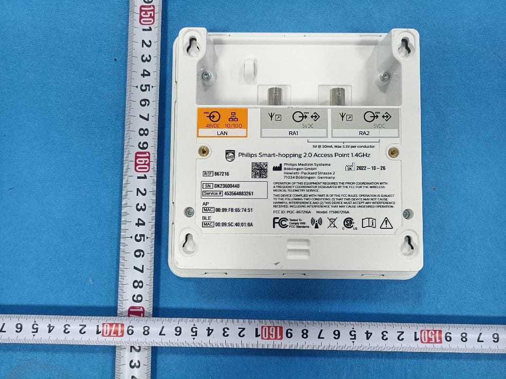
PQC-867216A
Jan 15, 2023Access Point
Equipment Class
DTS - Digital Transmission System
PQC-IITBV1
Mar 08, 20212.4G Radio Module
Equipment Class
DTS - Digital Transmission System
PQC-MX40SH1C4
Mar 31, 2014Intellivue MX40 1.4 GHz Patient Worn Device
Equipment Class
NII - Unlicensed National Information Infrastructure TX
PQC-OBRBSBV1
Nov 17, 2013CTG Base Station
Equipment Class
TNB - Licensed Non-Broadcast Station Transmitter