PQC-WMTS-ITS2ITS MODULE
Philips Medical Systems North America Co.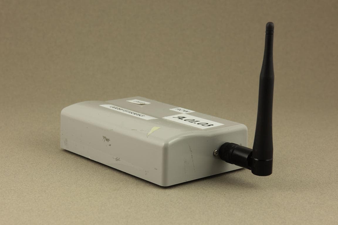
Click to zoom
Application Details
- Equipment Class
- TNB - Licensed Non-Broadcast Station Transmitter
- Date of Grant
- Jul 06, 2010
- Application Purpose
- Original Equipment
- Date of Application
- Jul 06, 2010
- Equipment Note
- ITS MODULE
- Frequency Range
- 1427.90000000 - 1431.10000000
- Country
- United States
Documents & Files
Document Text
Text extracted from the exhibit documents filed with the FCC. Open a document above to read the original.
Users Manual
Philips Medical Systems Confidential DOCUMENT NAME Application Note: WMTS-ITS2 1.4 GHz Radio Module 1. INTRODUCTION ................................................................................................................................ 2 2. HOST INTERFACE ............................................................................................................................ 2 3. SERIAL CONNECTION..................................................................................................................... 4 4. RF SHIELDING ................................................................................................................................... 6 5. MODULE MOUNTING CONSIDERATIONS ................................................................................. 6 6. RF INPUT/OUTPUT, ANTENNA ...................................................................................................... 6 7. RF TRANSMITTER SPECIFICATIONS ......................................................................................... 7 8. FAULT CONDITIONS ........................................................................................................................ 8 9. ACCOMPANYING DOCUMENTATION PRODUCTS INCORPORATING THE MODULE 10 ___________________________________________________________________ Application Note: WMTS-ITS2 The 1.4 GHz Radio Module Confidential Page 2 of 5 1. Introduction The Module is a serial network adapter designed to be used with specialized medical devices manufactured by Philips Medical Systems (Figure 1). It enables the host medical device to wirelessly establish bi-directional communication with other remote devices using the Philips’ WMTS infrastructure. Figure 1: Module Block Diagram 2. Host Interface The Module interfaces to the host through a single I/O connector (Figure 2). Via this connector the host supplies DC power, signal ground and modulating data to the radio Module. The communication between the host device and the Module is a two wire asynchronous serial interface (Table 1). Figure 2: Module Interface Host Connector ___________________________________________________________________ Application Note: WMTS-ITS2 The 1.4 GHz Radio Module Confidential Page 3 of 5 3. Serial Connection Serial Specification: The interface to the Host is a serial communication link (Table 2): • Flow Control: Tx, Rx; no hardware flow control • Baud Rate: 115.2 kbaud; • Parity: No parity bit • Bits: 8 bits of data, plus 1 Start/Stop bits • Logic Levels: TTL, 5 volt tolerant Maximum User Data Rate: The maximum user data rate that the radio supports is 12 kbits/second in each direction. This maximum over the air date rate is fixed by design and cannot be modified by the user. 4. RF Shielding The host device does not need to provide additional shielding. ___________________________________________________________________ Application Note: WMTS-ITS2 The 1.4 GHz Radio Module Confidential Page 4 of 5 5. Module Mounting Considerations The Module is self-contained and can be mounted anywhere using the supplied threaded pems nuts. Not special heat sinking considerations are required. There are not orientation constraints. 6. RF Input/Output, Antenna The Module is approved for use, with only the antennas specified by Philips and listed here: • Dipole Whip Philips Part Number M4842-61300 • Tri-Band Philips Part Number M3002-66493 • Dual-Band Philips Part Number M8100-66490 These antennas may not be replaced with antennas of a different type. However, antennas of equivalent type with equal or lower gain to the listed antennas may be used. The RF input and output of the Module is matched to 50 ohms. The Module has a coaxial cable with which allows for the connection of the RF to the antenna by way of a non-standard connector manufactured by JST. For the dipole whip, the connection is JST-to-reversed-TNC adaptor made by Amphenol at the point where the antenna connects. 7. RF Transmitter Specifications The following table summarizes general transmitter specifications (Table 3). 1. Frequency ranges: Bands: 1395 - 1400 MHz and 1427 - 1432 MHz 2. RF Output Power 8 dBm +2/-1.5dB (4.5 mW to 10 mW, nominal 6.3 mW), into Antenna load, calibrated into 50 Ohms UFL connector port. 3. RF Output Power control a) Transmitter chain gain shall be calibrated at time of manufacture (env temp 25+/-5deg.C). b) Power control algorithm deployed to prevent excess power and also includes temperature compensation. 4. Transceiver frequency accuracy during normal operation <+60/-100KHz relative to channel frequency, includes temperature compensation & aging effects. 5. Reference Frequency Accuracy 10ppm max over operating temperature 6. Modulation type GFSK, Gaussian Frequency Shift keying (1M40Q7D) ___________________________________________________________________ Application Note: WMTS-ITS2 The 1.4 GHz Radio Module Confidential Page 5 of 5 8. Fault Conditions Over / Under Voltage The input voltage from the DC power source to the Module must remain between the values specified in Table 1. Operating the radio Module from a voltage lower than 4.75 V dc or higher than 5.25 V dc can cause the regulator to shut down ceasing operation of the Module. Excessive Signal Level on Serial Input The data input signal levels must adhere to levels specified in Table 2. Driving the input data line over 5V dc can cause damage to the Module input buffers, causing interruption of data transfer. Excessive Data Rate on Serial Input The host serial communication data rate is fixed at 115.2 kbaud. Clocking data at different baud rates will result in incorrect data transfer. The maximum host/user over the RF link data rate is 12 kbps. Attempting to send data at a faster rate will result in data buffer overrun and data loss. 9. Accompanying Documentation Products Incorporating the Module Products which incorporate this device will be labeled, “Contains FCC ID: PQC-WMTS- ITS2,” and their accompanying documentation shall p…
Text truncated - open the document above for the full version.
Cover Letter(s)
Philips Medical Systems PH I LI PS Letter Of Agency Date: 12-April-20 10 To Whom It May Concern: Please be advised that Terrence Sweeney of Philips Medical Systems authorizes Larry Stillings of Compliance Worldwide, Inc. to act on our behalf, until otherwise notified, for applications submitted for the purpose of obtaining an FCC Grant of Equipment Authorization.We certify that we are not subject to denial of federal benefits, that includes FCC benefits, pursuant to Section 5301 of the Anti-Drug Abuse ACT of 1988, U.S.C. 862. Further, no party, as defined in 47 CAR 1.2002(b), to the application is subject to denial of federal benefits, that includes FCC benefits. Thank you for your attention to this matter. Sincerely Terrence J. Sweeney Vice President — Global Clinical Affairs
Cover Letter(s)
Philips Medical Systems P H I LI PS Date:5-May-201 0 Federal Communications Commission Authorization and Evaluation Division Confidentiality Request regarding application for certification of FCC ID: PQC- WMTS-ITS2 Pursuant to Sections 0.457 and 0.459 of the Commission’s Rules, we hereby request confidential treatment of information accompanying this application as outlined below: Exhibit Type File Name Block Diagram WMTSITS2 BIkDia.pdf Schematics WMTSITS2 Schem.pdf Operational Description WMTSITS2 OpDes.pdf Parts List WMTSITS2 PartsLst.pdf The above materials contain trade secrets and proprietary information not customarily released to the public. The public disclosure of these materials may be harmful to the applicant and provide unjustified benefits to its competitors. The applicant understands that pursuant to Section 0.457 of the Rules, disclosure of this application and all accompanying documentation will not be made before the date of the Grant for this application. Pursuant to DAO4-1 705 June 15, 2004 of the Commission’s public notice, we also require temporary confidential treatment of information accompanying this application as outlined below: Exhibit Type File Name External Photos WMTSITS2 ExtPho.pdf Internal Photos WMTSITS2 lntPho.pdf Temporary confidentiality from public disclosure is important for Philips Medical Systems from a commercial perspective. It enables the company to complete its development and regulatory efforts prior to introducing the product to the marketplace. Releasing information on the product via the FCC website prior to formal market introduction can be confusing to our customers and the medical community, and places the company at a competitive disadvantage. Sincerely, cfrj~ Terrence J. Sweeney VP — Global Clinical Affairs
Cover Letter(s)
Philips Medical Systems P H I LI PS June 7,2010 Federal Communications Commission Washington, DC 20554 RE: Request for Limited Modular Approval for PQC-WMTS-ITS2 To Whom It May Concern: Philips Medical Systems of Andover, Massachusetts herby submits the enclosed application for Equipment Authorization under 47 CFR Part 95, Subpart H for a wireless medical telemetry transmitter module, whose FCC grant ID would be PQC-WMTS-ITS2. This module incorporates the same radio technology and implementation as that used in the Philips TRx4S41A. This device differs in that it is modular, intended to be incorporated into certain Philips patient monitors, thereby providing wireless communication to existing infrastructure in healthcare facilities. The module complies with FCC Rules as a self-contained entity; it does not rely on external mounting or shielding or other inputloutput mechanisms to achieve compliance to either Parts 15 or 95 of the FCC Rules. The module is not being offered for sale as an OEM component, it is for incorporation into Philips Medical Systems products only. Upon receipt of this grant, the grant ID will be applied to the device. Furthermore, the instruction to the user concerning frequency coordination (as per 47 CFR 95.1109) will appear on the module. Products which incorporate this device will be labeled “Contains PQC-WMTS-ITS2”, and their associated Instructions for Use will also advise the user concerning frequency coordination (47 CFR 95.1109). Thank you in advance for your consideration of this application. Sincer ly, Terrence J. weeney VP — Global Clinical Affairs
External Photos
External Photos – Philips ITS 4841A, FCC ID: PQC-WMTS-ITS2
ID Label/Location Info
PQC-WMTS-ITS2 Label Location
Internal Photos
Internal Photos – Philips ITS 4841A, FCC ID: PQC-WMTS-ITS2 Transmitter module
Test Report
Compliance Worldwide, Inc. - 357 Main Street - Sandown, NH 03873 (603) 887 3903 Fax 887 6445 http://www.complianceworldwide.com COMPLIANCE WORLDWIDE INC. TEST REPORT 147-10R2 In Accordance with the Requirements of Federal Communications Commission CFR 47 Part 95, Subpart H Low Power Licensed Radio Communication Devices Wireless Medical Telemetry Service Transceiver In the bands 1395-1400 and 1427-1432 MHz Issued to Philips Medical Systems 3000 Minuteman Drive Andover, MA 01810 978-659-2800 for ITS4841A 1.4 GHz Instrument Telemetry Module With Cost Reduced LP1 Radio Board, P/N 453564193531 FCC ID: PQC-WMTS-ITS2 R2 report Issued on June 25, 2010 Original Report Issued on March 12, 2010 Tested by This test report shall not be reproduced, except in full, without written permission from Compliance Worldwide, Inc. Test Number: 147-10R2 Issue Date: 05/19/2010 Page 2 of 33 Compliance Worldwide, Inc. - 357 Main Street - Sandown, NH 03873 (603) 887 3903 Fax 887 6445 http://www.cw-inc.com Table of Contents 1. Scope........................................................................................................................................ 3 2. Product Details.......................................................................................................................... 3 2.1. Manufacturer ..................................................................................................................... 3 2.2. Model Number ................................................................................................................... 3 2.3. Serial Number.................................................................................................................... 3 2.4. Description......................................................................................................................... 3 2.5. Power Source .................................................................................................................... 3 2.6. EMC Modifications............................................................................................................. 3 3. Product Configuration ............................................................................................................... 3 3.1. Operational Characteristics & Software............................................................................. 3 3.2. EUT Hardware................................................................................................................... 4 3.3. EUT Hardware/Software/Firmware Revision Level ........................................................... 4 3.4. EUT Cables/Transducers .................................................................................................. 4 3.5. Support Equipment............................................................................................................ 4 3.6. Support Equipment Cables/Transducers........................................................................... 5 3.7. Block Diagram ................................................................................................................... 5 4. Measurements Parameters....................................................................................................... 6 4.1. Measurement Equipment Used to Perform Test ............................................................... 6 4.2. Measurement & Equipment Setup..................................................................................... 6 4.3. Test Procedure .................................................................................................................. 6 4.4. Measurement Uncertainty ................................................................................................. 6 5. Choice of Equipment for Test Suits ..........................................................................................7 5.1. Choice of Model................................................................................................................. 7 5.2. Presentation ...................................................................................................................... 7 5.3. Choice of Operating Frequencies ..................................................................................... 7 6. Measurement Summary............................................................................................................ 7 7. Measurement Data ................................................................................................................... 8 7.1. Occupied Bandwidth.......................................................................................................... 8 7.1. Radiated Field Strength of Fundamental ......................................................................... 13 7.2. Radiated Field Strength of Harmonics............................................................................. 18 7.4. Band Edge....................................................................................................................... 20 7.5. Spurious Radiated Emissions.......................................................................................... 25 7.6. Frequency Stability .......................................................................................................... 28 7.7. Conducted Emissions...................................................................................................... 29 7.8. RF Safety......................................................................................................................... 32 Test Number: 147-10R2 Issue Date: 05/19/2010 Page 3 of 33 Compliance Worldwide, Inc. - 357 Main Street - Sandown, NH 03873 (603) 887 3903 Fax 887 6445 http://www.cw-inc.com 1. Scope This test report certifies that the Philips cost reduced LP1 radio board from RTX, P/N 453564193531, for the ITS4841A 1.4 GHz Instrument Telemetry Module, using 1.9 GHz DECT technology, as t…
Text truncated - open the document above for the full version.
Test Setup Photos
Test Set Up Photos – Philips ITS 4841A , FCC ID: PQC-WMTS-ITS2 Radiated, Front - Dual Band Radiated, Rear – Dual Band Radiated, Front – Whip Radiated, Rear – Whip Frequency Stability Frequency Stability
Contact Information
Applicant
Delroy Smith(Principal Architect)
Test Firm
Compliance Worldwide, Inc.Deb Bourbeau
Technical Specifications
| # | Rule Parts | Frequency Range | Power Output | Emission | Tolerance |
|---|---|---|---|---|---|
| 2 | 95H | 1.43 GHz - 1.43 GHz | 17.00 mW | 1M1F1D | 1.1 Hz |
Other Applications from Philips Medical Systems North America Co.
PQC-AIM
Apr 14, 2024AIM
Equipment Class
DTS - Digital Transmission System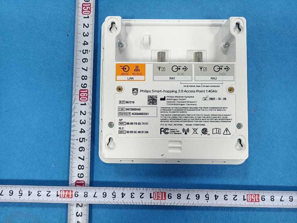
PQC-867216A
Jan 15, 2023Access Point
Equipment Class
DTS - Digital Transmission System
PQC-IITBV1
Mar 08, 20212.4G Radio Module
Equipment Class
DTS - Digital Transmission System
PQC-MX40SH1C4
Mar 31, 2014Intellivue MX40 1.4 GHz Patient Worn Device
Equipment Class
NII - Unlicensed National Information Infrastructure TX
PQC-OBRBSBV1
Nov 17, 2013CTG Base Station
Equipment Class
TNB - Licensed Non-Broadcast Station Transmitter