PQC-WMTS-MODULEWMTS Radio Module
Philips Medical Systems North America Co.
Click to zoom
Application Details
- Equipment Class
- TNT - Licensed Non-Broadcast Transmitter Worn on Body
- Date of Grant
- Apr 26, 2005
- Application Purpose
- Original Equipment
- Date of Application
- Mar 09, 2005
- Equipment Note
- WMTS Radio Module
- Frequency Range
- 1395.00000000 - 1432.00000000
- Country
- United States
Documents & Files
Document Text
Text extracted from the exhibit documents filed with the FCC. Open a document above to read the original.
Users Manual
Page 1 of 6 Patient Monitoring Quality & Regulatory Group 3000 Minuteman Road Mailstop 0490 Andover, MA 01810 Tel: (978) 659-7383 Fax: (978) 685-5624 Application Note: WMTS-MODULE Prepared by: Juan Brea Last revised: 10-Mar-05 The following information is intended for Philips internal use only. It is a guide for the incorporation of the WMTS-MODULE into Philips patient monitoring medical devices. Interested Philips engineers should contact the Wireless ER Manager for additional information and referral to specific design specialists. This document is an internally controlled document under the Philips Quality System. Philips Medical Systems Page 2 of 6 1 Table of Contents 1 Table of Contents ..................................................................................................................... 2 2 Introduction............................................................................................................................... 3 3 Host Interface ........................................................................................................................... 3 4 Serial Connection ..................................................................................................................... 4 4.1 Serial Specification:...........................................................................................................4 4.2 Maximum User Data Rate:................................................................................................ 4 5 WMTS-MODULE RF Shielding. ............................................................................................... 4 6 WMTS-MODULE Mounting Considerations............................................................................. 5 7 RF Input/Output, Antenna ........................................................................................................5 7.1 RF Transmitter Specifications ........................................................................................... 5 8 Fault Conditions ....................................................................................................................... 5 8.1 Over/ Under Voltage ......................................................................................................... 5 8.2 Excessive Signal Level on Serial Input ............................................................................. 6 8.3 Excessive Data Rate on Serial Input ................................................................................ 6 9 Accompanying Documentation for products incorporating the WMTS-MODULE.................... 6 Page 3 of 6 2 Introduction The WMTS-MODULE is a serial network adapter designed to be used with specialized medical devices manufactured by Philips Medical Systems (Figure 1). It enables the host medical device to wirelessly establish bi directional communication with other remote devices using the Philips’ WMTS infrastructure. Figure 1: WMTS-MODULE Block Diagram 3 Host Interface The WMTS radio module interfaces to the host though a single I/O connector (Figure 2). Via this connector the host must supply DC power, signal ground and modulating data to the radio module. The communication between the host device and the radio module is a two wire asynchronous serial interface (Table 1). Figure 2: WMTS-MODULE Interface Host Connector 53 1 642 WMTS Radio 6 pin header AMP 7 -338069-6. +5 Vdc Serial Data Radio Module Sheet Metal Housin g Ground Coaxial RF cable RF antenna Page 4 of 6 Pin Name I/O Function 1 Ground First of two ground connections for the module. 2 ITS_Tx OUT Serial data to host. 3 ITS_Rx IN Serial data from host. 4 Ground Second of two ground connections for the module. 5 +5 vdc + 5 vdc +/- 5%, Sinks 35 mA average, 280 mA Peak during radio Tx/Rx 6 Not Connected Table 1: Host Connector pin assignment 4 Serial Connection 4.1 Serial Specification: The interface to the Host is a serial communication link (Table 2): Æ Flow Control: Tx, Rx; no hardware flow control Æ Baud Rate: 115.2 kbaud; Æ Parity: No parity bit Æ Bits: 8 bits of data, plus 1 Start/Stop bits Æ Logic Levels: TTL levels, 5 volt tolerant. Logical Zero Logical One Conditions LOW HIGH 0.1 V max 100uA sink 0.55V max 24mA sink 2.9V min 100uA load ITS_Tx 2.3V min 24mA load ITS_Rx 0.6V max 2.2V min - Table 2: Serial Lines, Electrical DC Characteristics 4.2 Maximum User Data Rate: The maximum user data rate that the radio supports is 12 kbits/second in each direction. This maximum over the air data rate is fixed by design and cannot be modified by the user. 5 WMTS-MODULE RF Shielding. The module contains all necessary RF shielding. The host device does not need to provide additional shielding. Page 5 of 6 6 WMTS-MODULE Mounting Considerations. The module is self-contained and can be mounted anywhere using the supplied threaded pem nuts. No special heat sinking considerations are required. There are no orientation constraints. 7 RF Input/Output, Antenna The WMTS Radio Module is only approved for use with the antenna specified by Philips, part number M4842-61300. This antenna cannot be replaced with an antenna of a different type. The RF input and output of the WMTS-MODULE is matched to 50 ohms. A coaxial cable brings the RF outside the metal enclosure. This cable uses a unique non standard connector manufactured by JST (JST part number AYUI-1S-12676-221). The coaxial cable connects to a JST to reversed TNC adapter made by Amphenol (Amphenol part number 031-6101) where the antenna plugs in. The antenna is made by Radial to Philips’ specifications (Philips specifications number A-M4842- 61300-1, rev A). 7.1 RF Transmitter Specifications The following table summarizes general transmitter specifications (Table 3). For complete details (including details on the receiver section) refer to ES-M4840-90108: 1. Frequency ranges: Bands: 1395 - 1400 MHz and 1427 - 1432 MHz 2. RF Output Power 8 dBm +2/-3dB, 6.3 mW (3.2 mW to 10 mW), into Antenna load. Calibrated int…
Text truncated - open the document above for the full version.
Contact Information
Applicant
Delroy Smith(Principal Architect)
Technical Contact
Philips Medical SystemsBarry Wyshogrod
[email protected]978-659-7383
3000 Minuteman Road · Andover, Massachusetts · United States
Non-Technical Contact
Philips Medical SystemsBarry Wyshogrod
[email protected]978-659-7383
Test Firm
Compliance Worldwide, Inc.Robert McCall
Technical Specifications
| # | Rule Parts | Frequency Range | Power Output | Emission | Tolerance |
|---|---|---|---|---|---|
| 1 | 95H | 1.40 GHz - 1.43 GHz | 6.30 mW | 1M60Q7D | 15000.0000000000 Hz |
Other Applications from Philips Medical Systems North America Co.
PQC-AIM
Apr 14, 2024AIM
Equipment Class
DTS - Digital Transmission System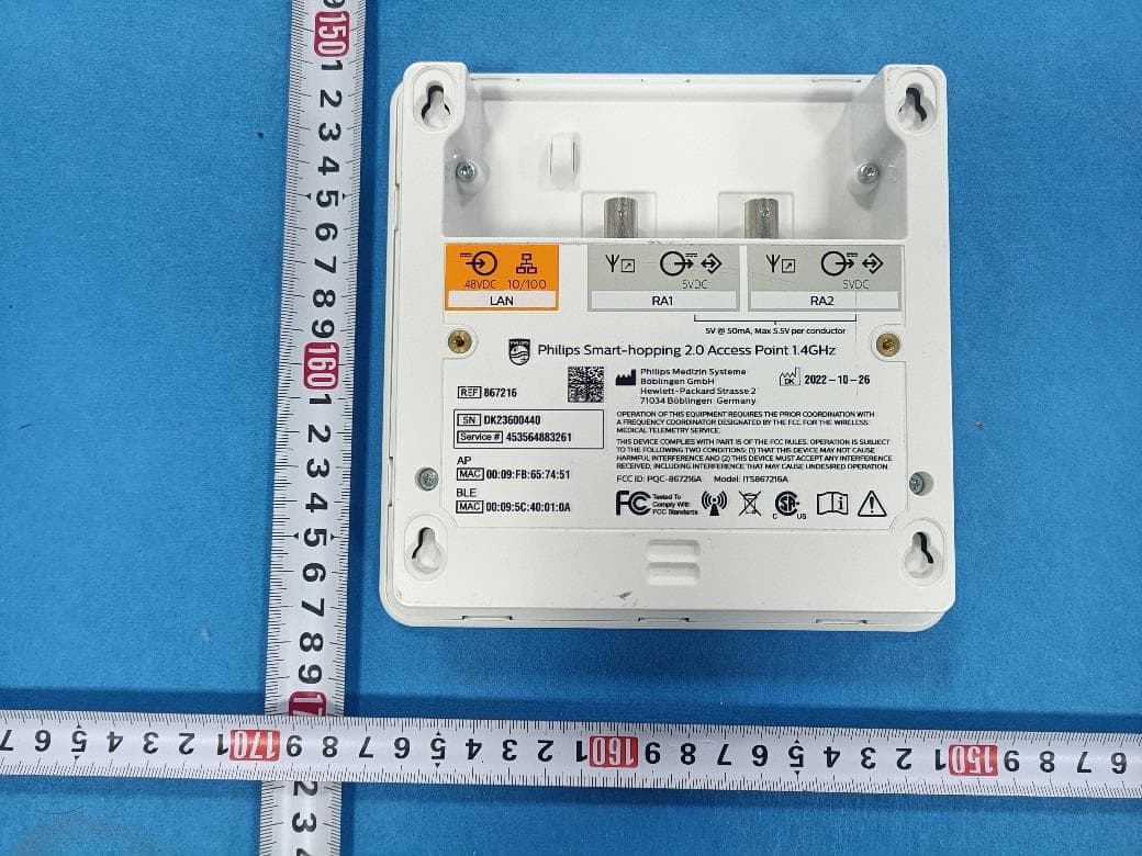
PQC-867216A
Jan 15, 2023Access Point
Equipment Class
DTS - Digital Transmission System
PQC-IITBV1
Mar 08, 20212.4G Radio Module
Equipment Class
DTS - Digital Transmission System
PQC-MX40SH1C4
Mar 31, 2014Intellivue MX40 1.4 GHz Patient Worn Device
Equipment Class
NII - Unlicensed National Information Infrastructure TX
PQC-OBRBSBV1
Nov 17, 2013CTG Base Station
Equipment Class
TNB - Licensed Non-Broadcast Station Transmitter