PQCM2601A-95Medical Telemetry Transmitter
Philips Medical Systems North America Co.
Click to zoom
Application Details
- Equipment Class
- TNT - Licensed Non-Broadcast Transmitter Worn on Body
- Date of Grant
- Sep 18, 2002
- Application Purpose
- Original Equipment
- Date of Application
- May 08, 2002
- Equipment Note
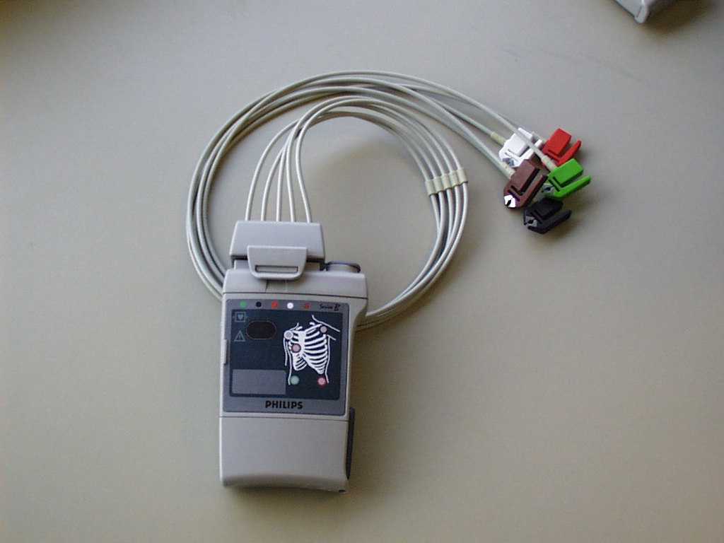
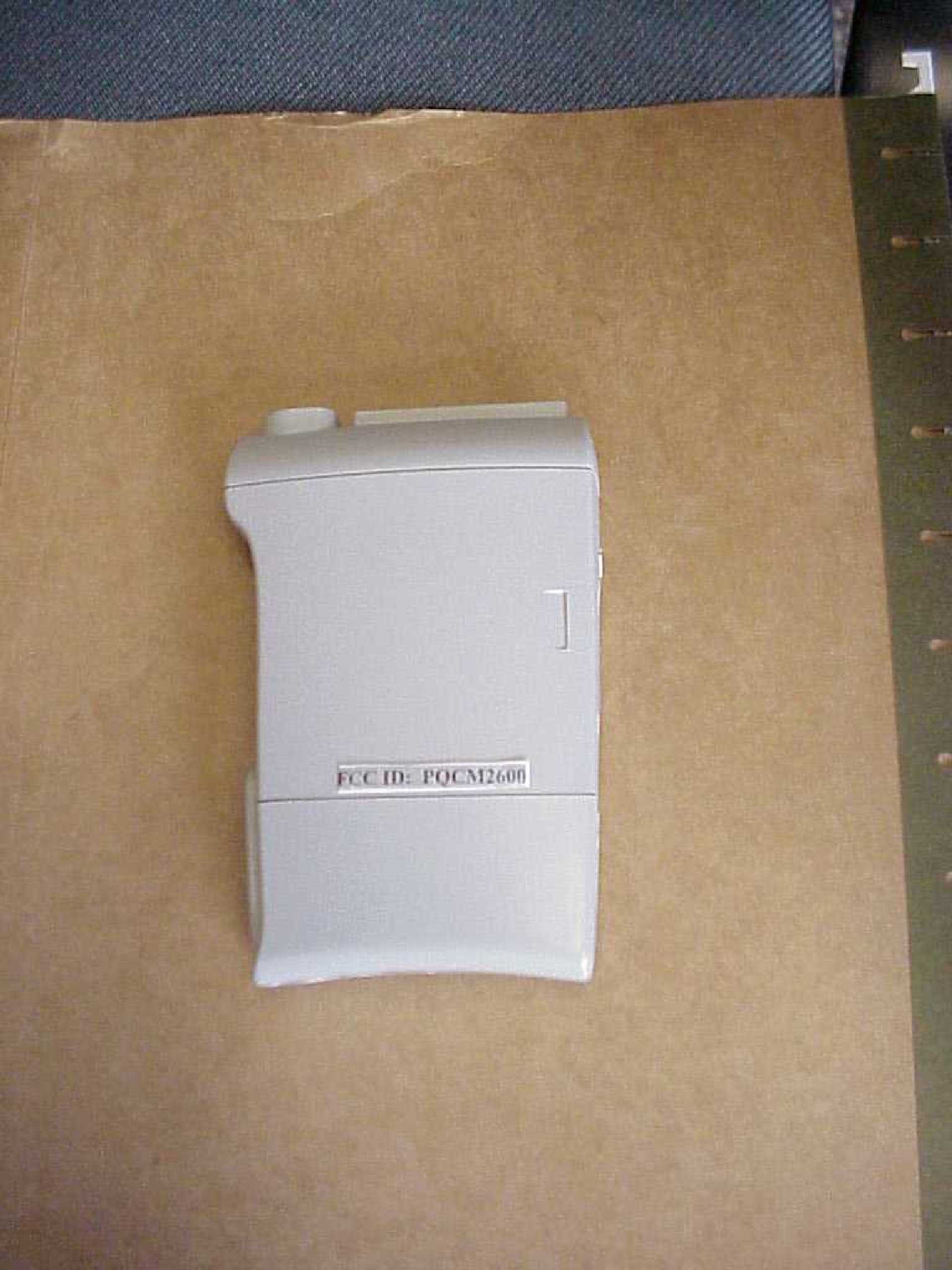
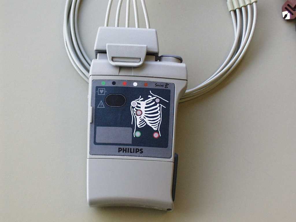
- Medical Telemetry Transmitter
- Frequency Range
- 608.00000000 - 614.00000000
- Country
- United States
Documents & Files
Document Text
Text extracted from the exhibit documents filed with the FCC. Open a document above to read the original.
Users Manual
Agilent Telemetry System User’s Guide Part Number M2600-9001C Printed in the U.S.A. July 2000 Edition 1 Copyright © 2000 by Agilent Technologies Inc. Notice This document contains proprietary information which is protected by copyright. All Rights Reserved. Reproduction, adaptation, or translation without prior written permission is prohibited, except as allowed under the copyright laws. Agilent Technologies, Inc. 3000 Minuteman Road Andover, MA 01810-1099 (978) 687-1501 Publication number M2600-9001C, Edition 1 Printed in USA July 2000 HP and Hewlett-Packard are registered trademarks of Hewlett-Packard Company. EASI™ is a registered trademark of Zymed, Inc. WarrantyThe information contained in this document is subject to change without notice. Agilent Technologies makes no warranty of any kind with regard to this material, including, but not limited to, the implied warranties or merchantability and fitness for a particular purpose. Agilent Technologies shall not be liable for errors contained herein or for incidental or consequential damages in connection with the furnishing, performance, or use of this material. Printing History iii Printing History New editions of this document incorporate all material updated since the previous edition. Update packages may be issued between editions and contain replacement and additional pages to be merged by a revision date at the bottom of the page. Pages that are rearranged due to changes on a previous page are not considered revised. The documentation printing date and part number indicate its current edition. The printing date changes when a new edition is printed. (Minor corrections and updates which are incorporated at reprint do not cause the date to change.) The document part number changes when extensive technical changes are incorporated. M2600-90201, First Edition.................................................... August 1998 Model M2604A Viridia Mainframe, revision D.01/D.02/D.03 Model M2601A Viridia Transmitter, revision A.00/A.01/A.02 Model M2605A Viridia Wave Viewer, revision A.00/A.01/A.02 Model M1403A Digital UHF Telemetry System with Option C03, revision D.01/D.02/D.03 M2600-90201, Second Edition............................................... February 1999 Model M2604A Viridia Mainframe, revision D.01/D.02/D.03 Model M2601A Viridia Transmitter, revision A.00/A.01/A.02 Model M2605A Viridia Wave Viewer, revision A.00/A.01/A.02 Model M1403A Digital UHF Telemetry System with Option C03, revision D.01/D.02/D.03 M2600-9001B, First Edition.................................................. February 2000 HP Telemetry System, Release B Model M2604A Viridia Mainframe, revision D.01/D.02/D.03 Model M2601A Viridia Transmitter, revision A.00/A.01/A.02/A.03 Model M2605A Viridia Wave Viewer, revision A.00/A.01/A.02 Model M1403A Digital UHF Telemetry System with Option C03, revision D.01/D.02/D.03 Printing History iv M2600-9001C, First Edition.................................................. July 2000 Agilent Telemetry System, Release C Model M2604A Agilent Mainframe, revision E.00 Model M2601A Agilent Transmitter, revision B.00 Model M2605A Agilent Wave Viewer, revision B.00 Details about the specific releases are contained in Appendix C. About this Book v About this Book This User’s Guide covers the use of the Agilent Telemetry System Release C with the Agilent Information Center. The User Guide contains information on performing day-to-day tasks and troubleshooting common problems as well as detailed information about all clinical applications. It includes lists of alarm and inoperative (INOP) messages, and configuration choices. Your purchased system may not include all the functionality described in this manual. When information pertains only to the EASI transmitters, the following EASI chest icon appears next to the title: User information for the Agilent Telemetry System is also contained in the Agilent Information Center On-line Help. Help focuses on how to complete basic tasks and troubleshoot problems. Appendix C, “System Releases,” summarizes the differences between the current version of the Agilent Telemetry System and earlier system releases. 1 2 3 4 5 EASI About this Book vi Document Conventions Procedures Procedures are indicated in text by the heading “Task Summary” followed by the following table: Bold Typeface Objects of actions in procedures appear in bold typeface. Note the following example: Click the Update button. Warnings Warning Warnings are information you should know to avoid injuring patients and personnel. Cautions Caution Cautions are information you should know to avoid damaging your equipment and software. Notes Note—Notes contain additional information on the Agilent Telemetry System usage. StepAction 1 2 3 Contents Contents-7 1. Introduction to the Agilent Telemetry System . . . . . . . . . . . . . . . . . . . . . . . . . 1-1 Indications for Use . . . . . . . . . . . . . . . . . . . . . . . . . . . . . . . . . . . . . . . . . . . . . . . . . . . . . . . . . . . . . 1-2 Condition . . . . . . . . . . . . . . . . . . . . . . . . . . . . . . . . . . . . . . . . . . . . . . . . . . . . . . . . . . . . 1-2 Prescription Versus Over-the-Counter . . . . . . . . . . . . . . . . . . . . . . . . . . . . . . . . . . . . . 1-2 Part of the Body or Type of Tissue with which the Device Interacts . . . . . . . . . . . . . . 1-2 Frequency of Use . . . . . . . . . . . . . . . . . . . . . . . . . . . . . . . . . . . . . . . . . . . . . . . . . . . . . . 1-2 Physiological Purpose . . . . . . . . . . . . . . . . . . . . . . . . . . . . . . . . . . . . . . . . . . . . . . . . . . 1-2 Patient Population . . . . . . . . . . . . . . . . . . . . . . . . . . . . . . . . . . . . . . . . . . . . . . . . . . . . . 1-2 Intended Use . . . . . . . . . . . . . . . . . . . . . . . . . . . . . . . . . . . . . . . . . . . . . . . . . . . . . . . . . 1-3 System Overview . . . . . . . . . . . . . . . . . . . . . . . . . . . . . . . . . . . . . . . . . …
Text truncated - open the document above for the full version.
Cover Letter(s)
Federal Communications Commission Washington DC 20554 9 May, 2002 Dear Sir or Madam, Philips Medical Systems (formerly Agilent Technologies) of Andover Massachusetts currently desires to submit an application for Equipment Authorization under Part 95, Subpart H for a wireless medical telemetry system (the M2601A telemetry transmitter). The M2601A currently has a Grant of Equipment Authorization under Part 15 for the range of 590-632 MHz (FCC Identifier PQCM2601A). This Form 731 application will be for the exact same device but specifically for the WMTS band of 608-614 MHz under Part 95. Upon receipt of this grant, additional labeling will be applied to our devices per 47 CFR 95.1109 as attached in the filing. In addition, I wish to modify the address and contact name for Grantee Code PQC to Denise Haley, as stated below. The previous contact name (T. Sweeney) and address (Bothell WA) were temporary as Agilent transferred to Philips Medical. Under FRN 0005142203, TIN 133429115, my name and address have already been modified in the CORES system but it was somehow not reflected in the Form 731 screen that came up on the screen. Thank you for your consideration of this application, and please do not hesitate to contact me should you require additional information. Sincerely, Denise Haley Quality and Regulatory Engineer Philips Medical Systems 3000 Minuteman Road Mail Stop 0490 Andover, MA 01810-1099 Tel: 978-659-2701 Fax. 978-685-5624 [email protected] formerly: Agilent Technologies Healthcare Solutions Group 3000 Minuteman. Road Andover, Massachusetts 01810 Tel: (978) 687 1501, Fax: (978) 794 7646 www.medical.philips.com Philips Medical Systems
Cover Letter(s)
Denise Haley Quality and Regulatory Philips Medical Systems (formerly Agilent Technologies, Inc.) 3000 Minuteman Road (MS 0490) Andover, MA 01810-1099 USA Tel: 978-659-2701 Fax: 978-685-5624 9 May, 2002 Dear Sir or Madam, Only if allowed, we wish to keep the contents of the Part 95 EMI Test Report (Emissions Data) as confidential information. Sincerely, Denise Haley Quality and Regulatory Engineer Tel: 978-659-2701 Manager: Elisabeth George, WW Quality and Regulatory Manager Tel: 978-659-4663
Cover Letter(s)
Copy of e-mail received 20 June, 2002: To:Denise Haley, Philips Medical Systems From:Steve Dayhoff [email protected] FCC Application Processing Branch Re:FCC ID PQCM2601A-95 Applicant: Philips Medical Systems North America Co. Correspondence Reference Number:23177 731 Confirmation Number:EA263790 1. Please submit clear schematic diagrams. The current schematics are unreadable. 2. Please submit external EUT photographs. ____________________________________________________________ Response: June 26, 2002 Hello Steve, Thank you for your e-mail. We were able to send the schematics out for .pdf format. I believe that the new files should be more readable. Please let me know if you encounter difficulties again. The external EUT pictures are also added today as attachments. We do not have EUT photos with the new labeling which will be on the back side (rear) of the M2601A transmitter, only a proposed drawing, because we are awaiting FCC approval of the content. It is expected that these new labels will be silk-screened onto the plastic housing. Thank you for your assistance while we pursue a Part 95 Grant. Please feel free to contact either me or David Jones should you have any questions or require additional information. Sincerely, Denise Haley Q&R Engineer, or David R. Jones, Q&R Manager Philips Medical Systems 3000 Minuteman Road, Mail Stop 0490 Andover, MA 01810 978-659-4825 [email protected] [email protected]
Operational Description
MDD Technical File: M2600A Telemetry System (Releases B&C; Projects TV 5.0, 6.0, 6.1) ____________________________________________________________________________ 12 December 2001 Rev.A Page 1 of 3 Philips Medical Systems M2600A Telemetry System: M2601A Medical Telemetry Transmitter General Information Manufacturer: Philips Medical Systems (formerly Agilent Technologies, Inc. and Hewlett Packard, Inc.) 3000 Minuteman Road Andover, MA 01810-1099 Tel: +1.978-659-4663 Fax: +1.978-685-5624 Authorized EU Representative Philips Medizinsystem Böblingen GmbH (formerly Agilent Technologies Deutschland GmbH and Hewlett-Packard GmbH) Hewlett Packard Str. 2 71034 Böblingen Germany Tel: +49-7031-464-8706 Fax: +49-7031-464-4297 Identity of other manufacturing sites for this device: NONE Product Identification: Model: M2600A Telemetry System Starting with Prefix Date Code 4036A for both series B and C transmitters • (Series B (TV 5.0): use of M2601A with battery extender device) • (Series C (TV 6.0): same M2601A device but has NBP SW capability for use with M2636A/B TeleMon monitors; a Series B transmitter cannot be used with TeleMon). General Device Description: Medical telemetry device Intended Use: The Philips/Agilent Te lemetry System is a comprehensive ambulatory system solution for the intermediate care unit for adult and pediatric patients. The foundation of the system is a transmitter that can capture and transmit ECG signals and SpO2 values (if available) that are then processed and displayed on the Philips/Agilent Information Center. The information center generates alarms and recordings, thus notifying clinicians of changes in patients' conditions. The Telemetry System communicates with other devices via the Philips/Agilent patient care system. MDD Technical File: M2600A Telemetry System (Releases B&C; Projects TV 5.0, 6.0, 6.1) ____________________________________________________________________________ 12 December 2001 Rev.A Page 2 of 3 US law restricts this device to sale by or on the order of a physician. This product is intended for use in health care facilit ies by trained healthcare professionals. It is not intended for home use Accessories: • Battery (9 V Lithium or 8.4 V Zinc Air) • 3-Wire ECG Lead Sets (AAMI and IEC models M2590A, M2591A, M2594A, M2595A) • 5-wire ECG Lead Sets (AAMI and IEC models M2592A, M2593A, M2596A, M2597A) • Combiner shield (3 and 5 wire) models M2598A and M2599A • ECG Electrodes 14445x • ECG Electrode kits (M2201A, 40489E, 40493D, 40493E) • Transmitter pouch (9300-0768-050, 9300-0768-200) • SpO2 transducers (M1191A, M1192A, M1194A) • Wristband M1627A • Nellcor Oxisensor (M1930A/B, M1904A/B) • Adapter Cable for use with Nellcor disposable transducers (M1943A) • Battery Extender Device (M2611A) • M2636A/B TeleMon (separate device and MDD Technical File) MDD Technical File: M2600A Telemetry System (Releases B&C; Projects TV 5.0, 6.0, 6.1) ____________________________________________________________________________ 12 December 2001 Rev.A Page 3 of 3 Standards Used: 93/42/EECCouncil Directive 93/42/EEC of 14 June 1993 concerning medical devicesE EN 330 220-1,-2:1997Electromagnetic compatibility and Radio Spectrum Matters (ERM); Parts 1 and 2 as applicable. E EN 980:1996Graphical symbols for use in the labeling of medical devicesE EN 540:1993Clinical investigation of medical devices for human subjectsE EN 1041:1998Information supplied by the manufacturer with medical devicesE EN60601-1:1996 IEC 60601-1:1995 Medical electrical equipment - General requirements for safetyE EN60601-1-1:1996 IEC 60601-1-1:1995 MEDICA L ELEC TRICA L EQ UIPM EN T - G EN ERA L REQ UI REMEN TS FO R SAFETY - COLLATERAL STANDARD: SAFETY REQUIREMENTS FOR MEDICA L ELEC TRICA L SYS TEMS E EN60601-1-2:1997 IEC 60601-1-2:1993 Med ica l e lec tric a l eq uip me nt - Ge nera l req uire me nts fo r sa fe ty - Collate ra l sta ndard - Electro ma gne tic co mpatib ility - Req uire me nts a nd tests E EN60601-1-4:1996 IEC 60601-1-4:1996 MEDICA L ELEC TRICA L EQ UIPM EN T - G EN ERA L REQ UI REMEN TS FO R SAFETY - COLLATERAL STANDARD - PROGRAMMABLE ELECTRICAL MEDICA L SYS TEMS E 21 CFR 80121 CFR 801 LabelingE UL 2601-1:1997MEDICAL ELEC TRICAL EQ UIPMENT - GENERAL REQUIREMEN TS FOR SAFETY E CSA C22.2-601.1:1998MEDICAL ELEC TRICAL EQ UIPMENT - GENERAL REQUIREMEN TS FOR SAFETY E IEC 60529:1989Degrees of Protection Provided by EnclosuresE IEC 60878:1988Graphical Symbols for Electrical Equipment in Medical Practice FDA Guidance “DO IT BY DESIGN – An Introduction to Human Factors in Medical Devices” E 1999/5/ECRadio Equipment & Telecommunications Terminal Equipment EU DirectiveE IEC 60601-2-27:1994Particular Requirements for EC GE IEC 60417:1973Graphical Symbols for Use on Equipment.E ETSI/EN 300 220-1:1996PTT- Post, Telephone & Telegraphy, Radio Licensing, where appropriate.E FCC, CFR 47 part 15BFCC, Code of federal regulations – Telecommunications (Unintentional Rad ia tors ) E FCC, CFR 47 part 15CFCC, Code of federal regulations – Telecommunications (Intentional Radiators)E FCC, CFR 47 part 90.217FCC, Code of federal regulations – Telecommunications (Intentional Radiators)E Other Notes: This device does not incorporate any sterile components. This device does not incorporate a medicinal substance.
Parts List/Tune Up Info
Production Material Plan for the M2601A Transmitter: Part NumberDescriptio n M2601-60407AAMI Case Tube Assembly M2601-60408IEC Case Tube Assembly M2601-40043Case Tube M2601-60012Battery Extender Contact Assembly M2601-40027Contact Holder M2601-40028Contact Cover M2601-80004Flex Adhesive M2601-80005Holder to Cover Adhesive M2601-60016Flex C ircuit Assembly M2601-00701Flex C ircuit M2601-20017Power Contact M2601-40029Battery Door M2601-60014Holster Assembly M2601-40030Cradle M2601-60013Assy, Bayonet, Cable, Strain Relief M2601-20016Contact, Bayonet M2601-40031Bayonet M2601-40032Housing, Cable Connections M2601-40035Patient Connector, Female, Inner M2601-40036Patient Connector, Female, O uter M2601-60019Cable, Coax M2601-60188Power Supply, US, w/Cradle Assy M2601-60018Power Supply, US M2601-83054Label, Battery Extender Power Supply M2601-83055Battery Extender P.S. Instruction Sheet M2601-60017Wall Mount Power Supply Cable M2601-60014Holster Assembly M2601-60189Power Supply, Euro, w/Cradle Assy M2601-60183Power Supply, Euro M2601-83054Label, Battery Extender Power Supply M2601-83055Battery Extender P.S. Instruction Sheet M2601-60014Holster Assembly M2601-60190Power Supply, Japan, w/Cradle Assy M2601-60184Power Supply, Japan M2601-83054Label, Battery Extender Power Supply M2601-83055Battery Extender P.S. Instruction Sheet M2601-60014Holster Assembly M2601-60191Power Supply, UK, w/Cradle Assy M2601-60185Power Supply, UK M2601-83054Label, Battery Extender Power Supply M2601-83055Battery Extender P.S. Instruction Sheet M2601-60014Holster Assembly M2601-60192Power Supply, Australia, w/Cradle Assy M2601-60186Power Supply, Australia M2601-83054Label, Battery Extender Power Supply M2601-83055Battery Extender P.S. Instruction Sheet M2601-60014Holster Assembly M2601-60193Power Supply, S. Africa, w/Cradle Assy M2601-60187Power Supply, S. Africa M2601-83054Label, Battery Extender Power Supply M2601-83055Battery Extender P.S. Instruction Sheet M2601-60014Holster Assembly M2601-60174Batt. Ext. Contact Assy. & Door K it M2601-67002RF Cable Tool M2601-63020Jet Eye II M2601-83056Label, FCC ID #020 Upgrade M2601-84031EEPROM M2601-84051EEPROM M2601-84061EEPROM M2601-83300PTT Label, Multiple M2601-83321PTT Label, Canada M2600-90174Declaration of Conformity M2600-90173Antenna Cables Warning Sheet M2601-83101Caution Label Part NumberDescriptio n M2601-60120Extended UHF Main Board Learning Products M2600-9001B Telemetry System User Guide - English M2600-9002B Telemetry System User Guide – French M2600-9003B Telemetry System User Guide - German M2600-9004BTelemetry System User Guide – Dutch M2600-9005B Telemetry System User Guide -Spanish M2600-9006B Telemetry System User Guide - Italian M2600-9007B Telemetry System User Guide - Norwegian M2600-9008BTelemetry System User Guide -Swedish M2600-9009B Telemetry System User Guide -Finnish M2600-9011B Telemetry System User Guide -Danish M2600-9014B Telemetry System User Guide -Portuguese M2600-9015BTelemetry System User Guide – Greek M2600-9019BTelemetry System User’s Guide -Czech M2600-9020BTelemetry System User’s Guide -Polish M2600-9013B Telemetry System User’s Guide –Simplified C hinese M2600-9022BTelemetry System User’s Addendum #4 (CCM) M2600-9101BHP Viridia Telemetry System What’s New in Release B? – English M2600-9102BHP Viridia Telemetry System What’s New in Release B? – French M2600-9103BHP Viridia Telemetry System What’s New in Release B? – German M2600-9104BHP Viridia Telemetry System What’s New in Release B? – Dutch M2600-9105BHP Viridia Telemetry System What’s New in Release B? – Spanish M2600-9106BHP Viridia Telemetry System What’s New in Release B? – Italian M2600-9107BHP Viridia Telemetry System What’s New in Release B? – Norwegian M2600-9108BHP Viridia Telemetry System What’s New in Release B? – Swedish M2600-9109BHP Viridia Telemetry System What’s New in Release B? – Finnish M2600-9111BHP Viridia Telemetry System What’s New in Release B? – Danish M2600-9114BHP Viridia Telemetry System What’s New in Release B? – Portuguese M2600-90163Service Training K it M2600-90164Service Training K it M2600-90165Service Training K it M2600-90166Test and Inspection Guide M2600-90226Antenna System Installation Note M2600-90168Upgrade Instructions Installation Note M2600-90167Service Q uick Reference Guide M2600-90169System Installation and Config. Guide
Test Report
Viridia Medical Telemetry Transmitter Model M2601A ( Radiated Emissions FCC Part 95 Subpart H Test # B90433A ( Test Site Services, Inc. P.O. Box 766 Marlboro, MA 01752 U.S.A. PhonelFax: (508) 481-1684 This report sholl not be reproduced. in whole or in part without the written approval of Test Site Services Inc. )This report must not be used by the recipient to claim product endorsement by NVLAP or any other agency of the U.S. Government The test results stated in this report are valid only for the specific items tested ... ""' 9'007 Test Site Services, Inc. Report # B90433A Table of Contents 1 3 4 5 6 9 10 11 13 AI BI CI DI ' '..' "... GENERAL INFORMATION EQUIPMENT UNDER TEST DESCRIPTION TEST SUMMARY , BLOCK DIAGRAM BLOCK DIAGRAM DESCRIPTION CABLE DESCRIPTION SOFTWARE DESCRIPTION MODES OF OPERA TION TEST EQUIPMENT LIST , APPENDIX A, TEST DATA , APPENDIX B, TEST PHOTOGRAPHS APPENDIX C, TEST PROCEDURES APPENDIX D, MEASUREMENT FACILITIES INFORMATION - - Agilent Technologies EUT: Viridia Medical Telemetry Transmitter 11/18/99 Test Site Services, Inc page 1 of 10 Report # B90433A EMI Test Report for Agilent Technologies Test Number :B90433A Product Name Viridia Medical Telemetry Transmitter Regulation FCC Part 95 Subpart H Date 11/1 &'99 Report Reviewed & Accepted by: R A~ --1I..j~~:_) Agilent Technologies 3000 Minuteman Rd Andover, MA 01810 ~ (~) Report Issued By: Richard L. Wiedeman, Laboratory Director Tested By: Tom Charron. Test Engineer /'/;..e - s) [~ I:."t:: ,,-:"~ ~ -~. '.- Bob Quinn, Test Engineer Tested By: TIrU 1I.f1 nport J.s Mt voJk/ Iridall tilt .flg1tt*n.f ofT~.f1 SIIe ~" II.:. ~L AgiJent T eclmologies II/Ism EUT: Viridia Medical Telemetry Transmitter Report # B90433A page 2 of 10 Test Site Services, Inc Regulation FCC Part 95 Subpart H. Section 95 115 Sections 95 115(a),955(b) ANSI C63.4-1992 Test Method Test Type Certification Agilent Technologies Manufacturer EUT Type/Model # Viridia Medical Telemetry Transmitter / M2601A 1/18/99 Date(s) of Test Gordon Cook Engineer Engineer Customer Personnel ( John Bilodeau EMC Engineer TSS Personnel R. Wiedeman Test Engineer Bob Quinn Tom Charron Test Engineer Open Area Test Site Test Location Test Site Services, Inc 30 Birch St. Milford, MA 01757 U.SA I NonCE FCC RUI~2:955requireSiliata VerifiCationRe~rt for a Class A Computing DevIce must be signed by "an Official of the Company res~nsible for the device". A signaturebl~khas been pro~ded on the first page for this p~ose. () Agilent Technologies 11/18/99 - EUT: Viridia Medical Telemetry Transmitter Test Site Services, Inc. Report # B90433A page 3 of 10 The EUT is a (Viridia Medical Telemetry Transmitter Model 2601A) that monitors ECG and SPO2 patient levels and transmits data to a central receiver system. It operates on specific frequencies from 590 to 632 MHz. Three units were tested at the low, middle and high end of the band (590.0, 611.0,632.0 MHz.). These units (one at each frequency) were tested simultaneously in close proximity to each other for a worst case test configuration. The units were tested with optional AC adapters. A complete description of the EUT may be found on block identifier page one. The tests were run in a typical configuration including the following support equipment; 1) EUT 1 @ 590.0 MHz. 4) (3) SPO2 Sensors 2) EUT 2 @ 611.0 MHz. 5) (3) ECG Leads 3) EUT 3 @ 632.0 MHz. 6) (3) AC Adapters REASON FOR TEST c Certification per FCC Part 95.1115 +(608-614 MHz Band) CHANGES MADE DURING TEST None DEVIA nONS FROM STANDARD TEST METHOD Only the 611.0 MHz results are presented in this report. This is approximately at the mid- range of the allowed band. The data presented in this report is a subset of data from TSS Report B90433, which is compared to the specific limits of FCC, Subpart H, Section 95.1115. Agilent Technologies 11/18/99 EUT: Viridia Medical Telemetry Transmitter Test Site Services, Inc. Report # B90433A page 4 of to The EUT (Viridia Medical Telemetry Transmitter Model 2601A) complied with the FCC Part 95 Subpart H Limits for an intentional radiator when tested in the system configuration defined herein. The following table indicates the margins (i.e. difference between measurement point and limit) of the worst case data points: TEST CLASS MARGIN TO SPEC (dB) FREQUENCY (MHz) (Fundamental Frequency)-8.7 611.0 Per 95.1115(0) Undesired Emissions -1.3 2528.0 Above 960 MHz -2.2 1264.0 Per 95.1115(b) -2.4 1222.0 -2.7 2444.0 -3.9 2360.0 -4.1 1896.0 Undesired Emissions -0.4 569.00 Below 960 MHz -3.9 674.00 Per 95. 1115(b) -6.3 548.00 -7.9 653.00 -10.6 419.98 -11.1 223.99 (
Test Report
( ( g .-. rn Q) t.) t (/) ~ "'Q) n) f- < M M ~ C> J!) ~ ~ 0 & ~ C> - 0 \n Q) bO ~ Q, ~ Q) ~ ~ .- s ~ = ~ - ~ e. ~ ~ ~~ ~ Q) s Q) - Q) ~ - ~ rJ .- "'0 Q) ~ ~ .- "'0 .- ~ .- >- ~ r.s s ~ ~ bJ) ~ .- ~ ~ rJ 0 ~ CQ ~ '0 u '0 '0 :2 '0 -8 -8 .2 ~ - ~ - u - ",- .- u Cu ~ .- u .- CI)~-::>~ CI) ~ '0 CI) '0 "E..2U ..~~ ~.. 0.0 8.Qc~0 U .0 ~ .0.-'" n .. U .- .. U oJ B u u e >< U ~ .. .- c ~~~~..8t:c ~c!u~Qii:~8 II U . II II II II U ~~'tj~~£i.1ZI ~ ~ ~ ? ~ ~ - ~ ei u : a ~ : E: -1"0 0 I C ~ Ie 0 I,... U 1'-' I ~ f t 1 J !" ~ t t. t f 1. I I I I I I I I I I I I I I I I I I I I I I I I I I , , , I I I I I I I I I I '" Q) "OJ) 0 '0 c ~ u Q) f-- ~ "00 ~ 0- ~ ~ - ::; ~ ~ .~ ~ E- 'f; 5 -0 E- o-;; (.) :g ~ ~ :a :5 > ~ :::> ~ Test Site Services, Inc Report # B90433A page 6 of 10 EUT Technical Data - Block Identifier lA Description Viridia, Medical Telemetry Transmitter Manuf/Model Model No Agilent Technologies :M2601A Serial # 3836A29089 Application Pending FCC/FTZ Ident. Power (Rated) : 120 VAC 60 Hz. to 10 VDC 300 mA Current Power (Tested) 120 VAC 60 Hz. to 10 VDC Current : 300 mA Internal Options: 020 M/NPA41100300AOIRK External Options: Class 2 Transfonner (Ault Inc.) SPO2 Sensor (Hewlett Packard ECG Leads M/N Ml191A Frequencies Generated: 611.00 MHz. 12.8 MHz. 8.00 MHz. Comments 11/1&199 EUT: Viridia Medical Telemetry Transmitter Agilent Technologies Test Site Services, Inc. Report # B90433A page 7 of 10 Function DC Power Qty= Type Unshielded 1 foot Length # of Conductors 0.25 Meter Unshielded Connector Shell Part Number Miscellaneous Function DC Power Qty=l Type Un shielded 3 Meters Length # of Conductors Connector Shell 2 Unshielded Part Number Miscellaneous Function SPO2 Sensor Cable Qty=l Type Un shielded Meter Length # of Conductors 7 Connector Shell Unshielded Part Number Miscellaneous (D6-DIO) Qty=5 Function ECG Leads Type Shielded 1 Meter Length # of Conductors 2. Unshielded Connector Shell Part Number Miscellaneous Transmit Antenna ( page 8 of 10 Test Site Services, Inc Report # B90433A TInE M260l-1001S. Rev. A.O3.0l PART#/REV FUNC'nON REPEAT11ME Continuous Power on unit, starts automatically RUN INSTRUCTIONS OPERATIONAL MODE(s) DURING TEST ~ OPERA 110NAL MODES AVAILABLE: Monitor patient ECG and SP02 and transmit to central receiver system MODE TESTED: Same as above FUNCTION : Same as above Unit only operates in a single mode. RA nONALE - - EUT: Viridia Medical Telemetry Transmitter Agilent Technologies 11/18/99 Test Site Services, Inc. Report # B90433A page 9 of 10 EUT I/O Ports All testing was perfonned with the following cables/tenninators connected to the EUT I/O ports: EUT I/O Ports Cable Attached (All available by type) (Yes/No) ECG y SPO2 y D.C. Input Power y NOTE: : ONE of each TYPE of PORT must be cabled.FCC Tests Test Site Services, Inc Report # B90433A page 10 of 10 Cat I)..P, Equipment Type # Model # Serial # Manufacturer Ca. Date Used Spectrum Analyzer Hewlett-Packard 8568B 2207AO1917 8/9/99 8/9/00 x 2Hewlett-Packard 85650A 2043AOO249 8/9/99 Quasi-Peak Adapter 8/9/00 x 1 RF Pre-Selector Hewlett-Packard. 85685A 2648AOO500 8/9/99 8/9/00 x, Spectrum Analyzer 4 Hewlett-Packard 8566B 2532AO2250 5/8/99 5/8/00 5 85650A Hewlett-Packard 2521 AOO665 5/8/99 5/8/00 Quasi-Peak Adapter 85685A 2510AOO186 6 Hewlett-Packard 5/8/99 5/8/00 RF Pre-Selector 7 Spectrum Analyzer Hewlett-Packard 8595E 3331A004155/27/995/27/00 x 8 Com Power CG-520 20129 5/18/99 Comb Generator 5/18/00 9RF Probe Fischer F-33-1 367 1/14/99 14/00 10 RF Pre-Amplifier Hewlett-Packard 84470 1937AO2850 5/24/99 5/24/00 Pre-Amplifier 8449B 3008AOO952 Hewlett-Packard 5/27/99 5/27/00 12 Biconical Antenna SchwarzbeckBBA91 06 01015/11/99 5/11/00 x 13 Biconical Antenna Schwarzbeck BBA91 06 0102 5/11/99 5/11/00 '14Log Periodic Antenna Schwarzbeck UHALP9101 9107718 6/1/99 x 6/1/00 IS UHALP9107 0103 Log Periodic Antenna Schwarzbeck 6/1/996/t/DC 16 Mag Loop Antenna EMCO 6502 9307-2841 6/1/99 6/1/00 17 Horn Antenna EMCO 3115 9308-4132 1.0/17/99 x 10/17/00 18Active Monopole Ant EMCO3301B 9510-3625 5/29/995/29/00 x 19 Tuned Dipole Antenna Comp Design AIOO 4451/18/9g '18/00 x 20 Comp Design AIOO 494 Tuned Dipole Antenna 8/25/99 8/25/0C 21 USN3x24A Solar 8012-50-24 0103 9/15/98 9/15/99 22 LISN4x25 A Schwarzbeck NNLA8120 8120458A 8/21/99 8/21/99 23 LISN 4 x 100 A Schwarzbeck. NNLA8121 8121237 1/21/9~ 1/21/00 x 24 LISN 3 x25 A EMCO 3825/28904-1483 7/9/99 7/9/00 25 EMCO Daily Daily Daily Daily Daily x Antenna Mast 26 Mast Controller EMCO 1050 1267 x 27 Turntable Daily x Macton ;27 Turntable Controller EMCO8908-1290 Daily 101762 Daily x - - AgiJent Technologies 1/18/99 - EUT: Viridia Medical Telemetry Transmitter
Test Report
Viridia Medical Telemetry Transmitter Model M2601A ( Radiated Emissions FCC Part 95 Subpart H Test # B90433A ( Test Site Services, Inc. P.O. Box 766 Marlboro, MA 01752 U.S.A. PhonelFax: (508) 481-1684 This report sholl not be reproduced. in whole or in part without the written approval of Test Site Services Inc. )This report must not be used by the recipient to claim product endorsement by NVLAP or any other agency of the U.S. Government The test results stated in this report are valid only for the specific items tested ... ""' 9'007 Test Site Services, Inc. Report # B90433A Table of Contents 1 3 4 5 6 9 10 11 13 AI BI CI DI ' '..' "... GENERAL INFORMATION EQUIPMENT UNDER TEST DESCRIPTION TEST SUMMARY , BLOCK DIAGRAM BLOCK DIAGRAM DESCRIPTION CABLE DESCRIPTION SOFTWARE DESCRIPTION MODES OF OPERA TION TEST EQUIPMENT LIST , APPENDIX A, TEST DATA , APPENDIX B, TEST PHOTOGRAPHS APPENDIX C, TEST PROCEDURES APPENDIX D, MEASUREMENT FACILITIES INFORMATION - - Agilent Technologies EUT: Viridia Medical Telemetry Transmitter 11/18/99 Test Site Services, Inc page 1 of 10 Report # B90433A EMI Test Report for Agilent Technologies Test Number :B90433A Product Name Viridia Medical Telemetry Transmitter Regulation FCC Part 95 Subpart H Date 11/1 &'99 Report Reviewed & Accepted by: R A~ --1I..j~~:_) Agilent Technologies 3000 Minuteman Rd Andover, MA 01810 ~ (~) Report Issued By: Richard L. Wiedeman, Laboratory Director Tested By: Tom Charron. Test Engineer /'/;..e - s) [~ I:."t:: ,,-:"~ ~ -~. '.- Bob Quinn, Test Engineer Tested By: T…
Text truncated - open the document above for the full version.
Contact Information
Applicant
Delroy Smith(Principal Architect)
Technical Contact
Philips Medical SystemsDenise Haley
[email protected]978-659-2701
3000 Minuteman Road · Andover, Massachusetts · United States
Non-Technical Contact
Philips Medical SystemsDenise Haley
[email protected]978-659-2701
Test Firm
Test Site Services Co.Lawrence Lee
Technical Specifications
| # | Rule Parts | Frequency Range | Power Output | Emission | Tolerance |
|---|---|---|---|---|---|
| 1 | 95H | 608 MHz - 614 MHz | 4.00 mW | 16K0F1D | 2.5000000000 ppm |
Other Applications from Philips Medical Systems North America Co.
PQC-AIM
Apr 14, 2024AIM
Equipment Class
DTS - Digital Transmission System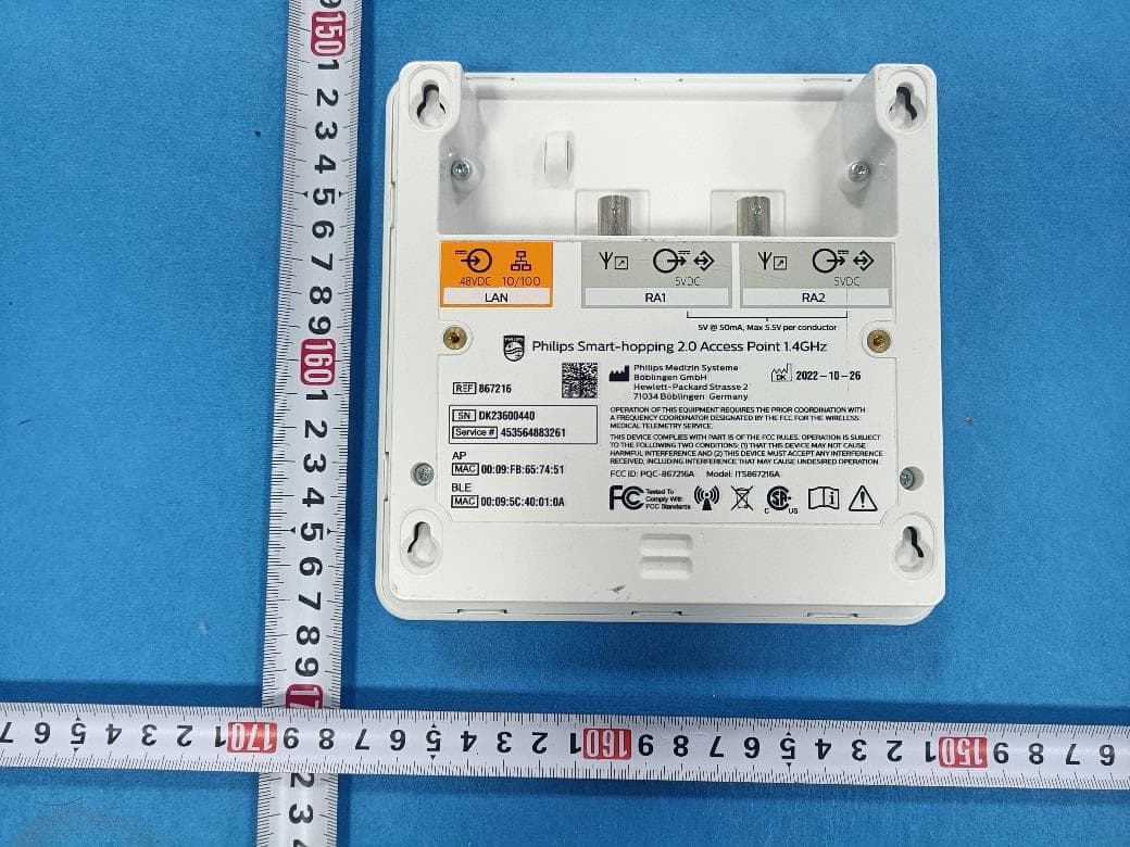
PQC-867216A
Jan 15, 2023Access Point
Equipment Class
DTS - Digital Transmission System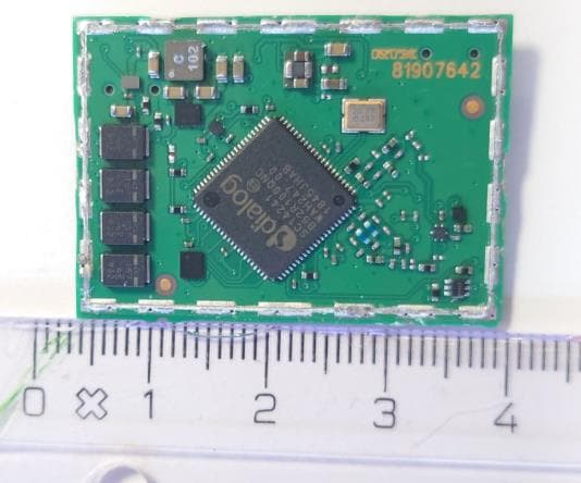
PQC-IITBV1
Mar 08, 20212.4G Radio Module
Equipment Class
DTS - Digital Transmission System
PQC-MX40SH1C4
Mar 31, 2014Intellivue MX40 1.4 GHz Patient Worn Device
Equipment Class
NII - Unlicensed National Information Infrastructure TX
PQC-OBRBSBV1
Nov 17, 2013CTG Base Station
Equipment Class
TNB - Licensed Non-Broadcast Station Transmitter