PQCM3813A2Low Power Transmitter
Philips Medical Systems North America Co.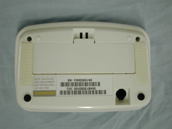
Click to zoom
Application Details
- Equipment Class
- DXX - Part 15 Low Power Communication Device Transmitter
- Date of Grant
- Dec 12, 2001
- Application Purpose
- Original Equipment
- Date of Application
- Dec 12, 2001
- Equipment Note
- Low Power Transmitter
- Frequency Range
- 916.50000000 - 916.50000000
- Country
- United States
Documents & Files
Document Text
Text extracted from the exhibit documents filed with the FCC. Open a document above to read the original.
Users Manual
44 Specifications ModelM3813A Type• Internally powered equipment • Type B applied part • IPXO Ordinary Equipment • Continuous operation AudioVoice readout of weight, prompts, and 3 volume settings, plus silence. Display• Digital, 0.7” (18 mm) character height • Weight displayed and announced simultaneously Measurement range66 to 330 lbs. (30 to 150 kg) Accuracy±1% ±1.1 lbs. (.5 kg) Display unitsPounds or kilograms, user-selectable Maximum allowable 330 lbs. (150 kg) weight Grab bar and columnRemovable attachment Power sourceFour type AA (1.5 volt) alkaline batteries connected in series (6.0 volts), included Battery lifeApproximately 6 months with daily measurement M3813-90001-UG-ENG-revD.qxd 4/27/01 3:42 PM Page 44 45 Scale User Guide Specifications Operating environment• 50º to 104º F (10º to 40º C) • 85% relative humidity • Atmospheric pressure 572 - 1013 hPa (0 - 15,000 feet or 0 - 4,600 meters of altitude) • WARNING: This equipment is not suitable for use in the presence of flammable anaesthetic mixture with air or with oxygen or nitrous oxide. • 15º to 130º F (-9º to 54º C) • 85% relative humidity • Atmospheric pressure 572 - 1013 hPa (0 - 15,000 feet or 0 - 4,600 meters of altitude) Dimension (approx.)• Height including column attachment: 40-7/8" (104 cm) • Length: 19-3/8” (49 cm) • Width including grab bars: 20" (51 cm) Weight (approx.)With column and batteries - 15 lbs. (6.8 kg) Transport and Storage environment M3813-90001-UG-ENG-revD.qxd 4/27/01 3:42 PM Page 45 46 Electromagnetic Compatibility The electromagnetic compatibility (EMC) validation of the M3813A Scale included testing performed according to the interna- tional standard for EMC with medical devices. See the Manufacturer’s Declaration for details. Electromagnetic Compatibility Testing During the test program, the Scale was subjected to many EMC tests, including both international standard and Agilent proprietary tests. During most of the testing no anomalies were observed. For one of the tests, EN 61000-4-3 Radiated Immunity, reduced per- formance was observed. EN 61000-4-3 specifies that the product be subjected to a field of 3 Volts/meter over a frequency range of 26 to 1000 MHz with no degradation of performance or loss of function below the perfor- mance level specified when equipment is operated as intended. At many of the test frequencies over the specified range, no anom- alies were observed. However, at a number of test frequencies, radio communications from the Scale to the M3812A Home Hub was disrupted. These reduced levels are as low as 0.04 V/m in the range from 800.732 MHz to 977.035 MHz. In addition, change in measured weight was excessive at some frequencies. These reduced levels are as low as 0.42 V/m at 32.998 MHz in the range from 26 MHz to 1000 MHz. The phenomena discussed above are not unique to this Scale, but are characteristic of medical and radio instrumentation in use today. The Home Hub is a radio receiver and its reception can be degraded by electromagnetic interference. Sensitive high gain cir- cuits used in measurements can be affected by electromagnetic interference. M3813-90001-UG-ENG-revD.qxd 4/27/01 3:42 PM Page 46 47 Scale User Guide Electromagnetic Compatibility Avoiding Electromagnetic Interference Problems Eliminating the source of interference or moving it away can pre- vent electromagnetic interference. Possible sources of interfering radio frequency radiation are cellular telephones, cordless tele- phones, or other products that contain radio transmitters. The Scale has a Radio Test Button that sends a reduced strength test radio sig- nal to the Home Hub, which sounds an audio tone if the test signal is successfully received. This test can be used to determine whether sources of interference are present. These sources can be turned off or moved away to reduce their strength and reduce interference. In addition, the Scale and the Home Hub can be placed closer to each other so that the radio transmission from the Scale to the Home Hub has less distance to travel and interfering radio signals have less effect. The radio transmission from the Scale is repeated periodically so that an intermittent source of interference should only delay reception. M3813-90001-UG-ENG-revD.qxd 4/27/01 3:42 PM Page 47 48 FCC Regulations This equipment has been tested and found to comply with the lim- its for a Class B digital device, pursuant to Part 15 of the FCC rules. These limits are designed to provide reasonable protection against harmful interference in a residential installation. This equipment generates, uses, and can radiate radio frequency ener- gy. If it is not installed and used in accordance with the instruc- tions, it might cause harmful interference to radio communica- tions. However, there is no guarantee that interference will not occur in a particular installation. If this equipment does cause harmful interference to radio or television reception, which can be determined by turning the equipment off and on, the user is encouraged to try to correct the interference by one or more of the following measures: • Re-orient or relocate the Home Hub. • Increase separation between the measurement devices or the Home Hub and the device being interfered with; e.g., the tele- vision. • Consult your Health Care Provider. Note:Any changes or modifications to the equipment that are not expressly approved by Agilent could void the user’s authority to operate this equipment. M3813-90001-UG-ENG-revD.qxd 4/27/01 3:42 PM Page 48
Block Diagram
A A B B C C D D E E 44 33 22 11 Matching network RFM TR1000 Antenna in PCB etch Transmit serial stream Transmit level select (Normal/Reduced) Transmitter enable/sleep Transmit level-set components RF block diagram A2 MSI Scale Interface: M3813-20300 A 11Thursday, September 06, 2001 eCare Services 3500 Deer Creek Rd., Palo Alto, CA 94304 Philips CONFIDENTIAL Title SizeDocument NumberRev Date:Sheetof
Cover Letter(s)
Curtis-Straus LLC 527 Great Road Littleton, Massachusetts 01460 Tel: 978.486.8880 Fax: 978.486.8828 Web: www.curtis-straus.com e-mail: [email protected] Worldwide Regulatory Approvals Experts ® Federal Communications Commission 7435 Oakland Mills Road Columbia, MD 21046 Gentlemen: This letter is to comply with 47 CFR 0.457(d)(2)(I) pertaining to confidential material. Philips Medical Systems requests that the following documents regarding this submission for FCC ID PQCM3813A2 be kept confidential: 1. Schematic 2. Bill of Materials The material above contains technical data, which would customarily be guarded from competitors. We at Curtis-Straus LLC are acting as an Agent on behalf of Philips Medical Systems in requesting confidentiality with regards to the preceding documents. Sincerely, Michael Buchholz Senior EMC Manager Curtis-Straus LLC 527 Great Road Littleton, MA 01460
External Photos
External Photos Agilent M3813A FCC ID: PQCM3813A2 Note: These pictures were taken before the official name change from Agilent to Philips. The label has since been changed to reflect the current company name. Agilent M3813A FCC ID: PQCM3813A2 Agilent M3813A FCC ID: PQCM3813A2 Note: The purpose of this picture is to show the label placement. See the label exhibit for the current label information.
Internal Photos
Internal Photos Agilent M3813A FCC ID: PQCM3813A2 Agilent M3813A FCC ID: PQCM3813A2
Operational Description
Description of the Philips Home Scale Transmitter circuit Robert C. Leichner 27 November 2001 The M3813 Home Scale transmitter circuit is based an R. F. Monolithics (RFM) TR1000 hybrid transceiver module. Printed circuit board load options have been selected to constrain the transceiver to three operating modes. The operating mode in effect at any given time is selected by the device microprocessor. The available modes are Standby, Transmit, and Test. • Standby mode is a very low power consumption state in which the transceiver consumes absolute minimum power, and emits no RF energy. • Transmit mode is constrained, again by load options, to ON-OFF keying. Transmit mode is the normal mode for transfer of measurement and status messages. Transmit mode is used during FCC part 15 testing. • Test mode is identical to Transmit mode except that RF output is reduced by approximately 3 dB. Test mode – rarely used - is used during device installation, and to verify RF link operation. A 19.6 kilobit serial data stream modulates the TR1000 output in Transmit and Test modes. Quoting from the RFM TR1000 data sheet: TR1000 916.50 MHz Hybrid Transceiver The TR1000 hybrid transceiver is ideal for short-range wireless data applications where robust operation, small size, low power consumption and low cost are required. The TR1000 employs RFM’s amplifier-sequenced hybrid (ASH) architecture to achieve this unique blend of character-istics. All critical RF functions are contained in the hybrid, simplifying and speeding design-in. The receiver section of the TR1000 is sensitive and stable. A wide dynamic range log detector, in combination with digital AGC and a compound data slicer, provide robust performance in the presence of on-channel interference or noise. Two stages of SAW filtering provide excellent receiver out-of-band rejection. The transmitter includes provisions for both on-off keyed (OOK) and amplitude-shift keyed (ASK) modulation. The transmitter employs SAW filtering to suppress output harmonics, facilitating compliance with FCC 15.249 and similar regulations. The TR1000 transmitter output power is determined by current flowing into TXMOD (pin 8 of the TR1000). The transmitter design supports both Transmit mode used to transfer Blood Pressure measurement results and status messages, as well as a reduced power test mode. R133 and R134 control the current into TR1000 pin 8 in the higher power normal mode. The two resistors are used in series to allow the combined resistance, and the resulting power level, to be set with greater precision than possible using a single standard resistor value. The data signal driving the resistors and the TR1000 TXMOD input is the output of a 74HC00 quad NAND gate. The 74HC00 output is lightly loaded by the transmitter, and when driven, will be stable and close to the power supply voltage. The power supply voltage is controlled by a linear regulator (Micrel MIC5219-3.0BM5) with better than 1% output load regulation and worst case accuracy of 2%. In combination, these factors result in a well-controlled drive signal to the RFM TR1000. R135 modifies the drive to the TXMOD pin by diverting a portion of the available drive current when RFattenuate- is asserted (LOW). Current into TXMOD, and the resulting TR1000 output level, are reduced when Rfattenuate- is asserted. R135 was selected to produce a 3dB drop in RF output level. D20 is reverse biased during Transmit mode assuring that R135 is isolated from the transmitter during non-test operation.
Test Report
MEASUREMENT/TECHNICAL REPORT Company: Philips Medical Systems Model: M3813A FCC ID: PQCM3813A2 October 10, 2001 Description: This is a report to support a request for an original grant of equipment authorization. Equipment Type: Low Power Communications Device Transmitter (DXX) Report prepared for: Philips Medical Systems 3500 Deer Creek Road Palo Alto, CA 94304 Phone: (650) 857-8720 Fax: (650) 236-9981 Report prepared by: Evan D. Gould Curtis-Straus LLC 527 Great Road Littleton, MA 01460 USA Phone: 978-486-8880 FAX: 978-486-8828 FCC Application for Philips Medical Systems••FCC ID: PQCM3813A2 •• Report No. EB1012-1 7-Dec-01 ______________________________________________________________________ _____________________________ ________________________________ Curtis-Straus LLC •• 527 Great Road •• Littleton, MA •• TEL (978) 486-8880 •• FAX (978) 486-8828 page 2 of 9 Introduction This report is an application for Certification of a Transmitter operating pursuant to Part 15.249 of the FCC Rules, Code of Federal Regulations 47. The model number covered by this report is M3813A. This report is designed to demonstrate the compliance of this device with the requirements outlined in Part 15 of CFR 47 using the methods outlined in Part 2 of CFR 47. The confidential information and descriptions included in this application are detailed descriptions of the products, block diagrams, component specifications, and schematic diagrams. We hereby respectfully request under the provision of section 0.457d of the code that the documents listed below be held confidential. Schematics Bill of Materials FCC Application for Philips Medical Systems••FCC ID: PQCM3813A2 •• Report No. EB1012-1 7-Dec-01 ______________________________________________________________________ _____________________________ ________________________________ Curtis-Straus LLC •• 527 Great Road •• Littleton, MA •• TEL (978) 486-8880 •• FAX (978) 486-8828 page 3 of 9 Statement of Conformity The Philips Medical Systems M3813A has been found to conform with the following parts of the 47 CFR as detailed below: Part 2 Part 15 Comments 15.15(b) The product contains no user accessible controls that increase transmission power above allowable levels. 2.925 15.19 The label is shown in the label exhibit. 15.21 Information to the user is shown in the instruction manual exhibit. 15.27 No special accessories are required for compliance. 15.203 The antenna is built into the board and there is no external antenna connection. 15.205 15.209 The fundamental is not in a Restricted band and the spurious and harmonic emissions in the Restricted bands comply with the general emission limits of 15.209. 15.207 The unit is battery powered without the capability of being recharged or operated from the AC mains. 15.249(a) The unit complies with the field strength limits of the 15.249(a) table including the 20dB peak restriction of 15.35(b) and 15.249(d). 15.249(c) The unit complies with the field strength limits of the 15.209(a) table. FCC Application for Philips Medical Systems••FCC ID: PQCM3813A2 •• Report No. EB1012-1 7-Dec-01 ______________________________________________________________________ _____________________________ ________________________________ Curtis-Straus LLC •• 527 Great Road •• Littleton, MA •• TEL (978) 486-8880 •• FAX (978) 486-8828 page 4 of 9 Test Methodology Radiated emission testing was performed according to the procedures in ANSI C63.4 (1992). The testing was performed at an antenna to EUT distance of 3 meters below 1 GHz, and at a distance of 3 or 1 meter(s) above 1 GHz. The actual test distance used is noted in the test data sheets. The device’s performance was investigated to 10GHz. The EUT was powered by four Duracell PC1500 PROCELL 1.5Volt AA batteries. Fresh batteries were used for all testing. The circuit board was hardwired so as to produce a continuous transmission signal as opposed to the momentary transmission that occurs during regular operation. Since the device is a table-top unit, the emissions were maximized around the vertical axis and the maximum reading was recorded. The integrated antenna cannot be maximized separately. All other performance tests were made in accordance with the procedures outlined in Part 15 of CFR 47. The applicable sections provided under Part 15 are provided in the measurement section of this report. FCC Application for Philips Medical Systems••FCC ID: PQCM3813A2 •• Report No. EB1012-1 7-Dec-01 ______________________________________________________________________ _____________________________ ________________________________ Curtis-Straus LLC •• 527 Great Road •• Littleton, MA •• TEL (978) 486-8880 •• FAX (978) 486-8828 page 5 of 9 Test Facility Curtis-Straus LLC All testing for the range 30–10,000MHz was performed at Curtis-Straus (A2LA Certificate Number 1627-01). The open area test site used to collect the radiated data is located at 527 Great Road, Littleton, MA 01460. Site “A” was used. FCC Application for Philips Medical Systems••FCC ID: PQCM3813A2 •• Report No. EB1012-1 7-Dec-01 ______________________________________________________________________ _____________________________ ________________________________ Curtis-Straus LLC •• 527 Great Road •• Littleton, MA •• TEL (978) 486-8880 •• FAX (978) 486-8828 page 6 of 9 Test Equipment Used SPECTRUM ANALYZERS x Analyzer Model No. Company Serial No. Calibration Due BLACK 9kHz-12.8GHz 8596E HP 3710A00944 29-JUN-2002 OPEN AREA TEST SITES (OATS) x Site FCC Code IC Code VCCI Code Calibration Due “A” Alaska 93448 IC 2762-A R-903/ C-480 23-JUN-2002 ANTENNAS x Antenna Model No. Company Serial No. Calibration Due RED Bilog: 30MHz-1GHz 3143 EMCO 1270 28-JUN-2002 YELLOW Horn: 1-18GHz 3115 EMCO 9608-4898 08-MAY-2002 PREAMPLIFIERS x Preamplifier Model No. Company Serial No. Calibration Due YELLOW-BLACK 1-20GHZ SMC-12A MITEQ 535055 21-SEP-2002 GREEN 0.01-2000MHz ZFL-1000-LN MiniCircuits/ C-S n/a 24-MAR-2002 Unless otherwise noted the calibration interval is o…
Text truncated - open the document above for the full version.
Test Setup Photos
Page 1 of 1 file://E:\Agilent\B1012\Setup Photo.jpg9/25/01
Contact Information
Applicant
Delroy Smith(Principal Architect)
Test Firm
Curtis-Straus LLCJonathan Stewart
Technical Specifications
| # | Rule Parts | Frequency Range | Power Output |
|---|---|---|---|
| 1 | 15C | 916.5 MHz - 916.5 MHz | - |
Other Applications from Philips Medical Systems North America Co.
PQC-AIM
Apr 14, 2024AIM
Equipment Class
DTS - Digital Transmission System
PQC-867216A
Jan 15, 2023Access Point
Equipment Class
DTS - Digital Transmission System
PQC-IITBV1
Mar 08, 20212.4G Radio Module
Equipment Class
DTS - Digital Transmission System
PQC-MX40SH1C4
Mar 31, 2014Intellivue MX40 1.4 GHz Patient Worn Device
Equipment Class
NII - Unlicensed National Information Infrastructure TX
PQC-OBRBSBV1
Nov 17, 2013CTG Base Station
Equipment Class
TNB - Licensed Non-Broadcast Station Transmitter