PQCM3813BTelemedicine Home Scale
Philips Medical Systems North America Co.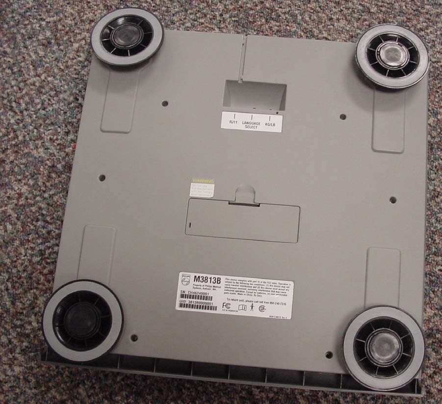
Click to zoom
Application Details
- Equipment Class
- DXX - Part 15 Low Power Communication Device Transmitter
- Date of Grant
- Aug 06, 2006
- Application Purpose
- Original Equipment
- Date of Application
- Aug 06, 2006
- Equipment Note
- Telemedicine Home Scale
- Frequency Range
- 916.50000000 - 916.50000000
- Country
- United States
Documents & Files
Document Text
Text extracted from the exhibit documents filed with the FCC. Open a document above to read the original.
Users Manual
Notice 2 Notice Proprietary Information Published by Philips Medical Systems, a division of Philips Electronics North America Corporation. Philips Medical Systems reserves the right to make changes to both this Instructions for Use and to the product it describes. Product specifications are subject to change without notice. Nothing contained within this Instructions for Use is intended as any offer, warranty, promise or contractual condition, and must not be taken as such. © Koninklijke Philips Electronics N.V. 2006 All Rights are reserved. Reproduction in whole or in part in any form or by any means, electrical, mechanical or otherwise, is prohibited without the written consent of the copyright holder. Document number: M3810-90096 Issue number 2, July 2006 Philips Medical Systems 3000 Minuteman Road Andover, MA 01810-1085 USA Unauthorized copying of this publication is a copyright infringement and will reduce the ability of Philips Medical Systems to provide accurate and up-to-date information to users. Non-Philips product names may be trademarks of their respective owners. Published in the United States of America Notice 3 Printing History New editions of this document will incorporate all material updated since the previous edition. Update packages may be issued between editions and contain replacement and additional pages to be merged by a revision date at the bottom of the page. Note that pages which are rearranged due to changes on a previous page are not considered revised. The documentation printing date and part number indicate its current edition. The printing date changes when a new edition is printed. (Minor corrections and updates which are incorporated at reprint do not cause the date to change.) The document part number changes when extensive technical changes are incorporated. All Editions and Updates of this manual and their publication dates are listed below. First Edition . . . . . . . . . . . . . . . . . . . . . . . . . . . October 2002 Second Edition . . . . . . . . . . . . . . . . . . . . . . . . . . . . July 2006 Notice 4 Contents Contents 1 1. Introduction. . . . . . . . . . . . . . . . . . . . . . . . . . . . . . . . . . . . . . . . . . . . . . .1-1 Welcome . . . . . . . . . . . . . . . . . . . . . . . . . . . . . . . . . . . . . . . . . . . . . . . . . . . . . . . . . . . . .1-1 How the System Works . . . . . . . . . . . . . . . . . . . . . . . . . . . . . . . . . . . . . . . . . . . . . .1-1 Keeping the System Working . . . . . . . . . . . . . . . . . . . . . . . . . . . . . . . . . . . . . . . . . .1-1 Thank You! . . . . . . . . . . . . . . . . . . . . . . . . . . . . . . . . . . . . . . . . . . . . . . . . . . . . . . . .1-1 Philips Telemonitoring Services System. . . . . . . . . . . . . . . . . . . . . . . . . . . . . . . . . . . . .1-2 Safety and Precautions. . . . . . . . . . . . . . . . . . . . . . . . . . . . . . . . . . . . . . . . . . . . . . . . . .1-3 Follow Instructions . . . . . . . . . . . . . . . . . . . . . . . . . . . . . . . . . . . . . . . . . . . . . . . . . .1-3 Document Conventions . . . . . . . . . . . . . . . . . . . . . . . . . . . . . . . . . . . . . . . . . . . . . .1-3 Warnings . . . . . . . . . . . . . . . . . . . . . . . . . . . . . . . . . . . . . . . . . . . . . . . . . . . . . . . . . . . . . 1-3 Cautions . . . . . . . . . . . . . . . . . . . . . . . . . . . . . . . . . . . . . . . . . . . . . . . . . . . . . . . . . . . . . 1-4 Notes . . . . . . . . . . . . . . . . . . . . . . . . . . . . . . . . . . . . . . . . . . . . . . . . . . . . . . . . . . . . . . . . 1-4 Bold Typeface . . . . . . . . . . . . . . . . . . . . . . . . . . . . . . . . . . . . . . . . . . . . . . . . . . . . . . . . . 1-4 Display Symbols . . . . . . . . . . . . . . . . . . . . . . . . . . . . . . . . . . . . . . . . . . . . . . . . . . . . . . .1-5 2. Philips Telemonitoring Set . . . . . . . . . . . . . . . . . . . . . . . . . . . . . . . . . .2-1 Overview . . . . . . . . . . . . . . . . . . . . . . . . . . . . . . . . . . . . . . . . . . . . . . . . . . . . . . . . . . . . .2-1 Device Descriptions . . . . . . . . . . . . . . . . . . . . . . . . . . . . . . . . . . . . . . . . . . . . . . . . . . . .2-2 Home Hub/TeleStation . . . . . . . . . . . . . . . . . . . . . . . . . . . . . . . . . . . . . . . . . . . . . . .2-2 Front Panel Lights . . . . . . . . . . . . . . . . . . . . . . . . . . . . . . . . . . . . . . . . . . . . . . . . . . . . . . 2-3 Warnings . . . . . . . . . . . . . . . . . . . . . . . . . . . . . . . . . . . . . . . . . . . . . . . . . . . . . . . . . . . . . 2-3 Cautions . . . . . . . . . . . . . . . . . . . . . . . . . . . . . . . . . . . . . . . . . . . . . . . . . . . . . . . . . . . . . 2-4 Scale . . . . . . . . . . . . . . . . . . . . . . . . . . . . . . . . . . . . . . . . . . . . . . . . . . . . . . . . . . . .2-5 Standard Scale . . . . . . . . . . . . . . . . . . . . . . . . . . . . . . . . . . . . . . . . . . . . . . . . . . . . . . . . 2-5 Steady Scale . . . . . . . . . . . . . . . . . . . . . . . . . . . . . . . . . . . . . . . . . . . . . . . . . . . . . . . . . . 2-5 Warnings . . . . . . . . . . . . . . . . . . . . . . . . . . . . . . . . . . . . . . . . . . . . . . . . . . . . . . . . . . . . . 2-6 Cautions . . . . . . . . . . . . . . . . . . . . . . . . . . . . . . . . . . . . . . . . . . . . . . . . . . . . . . . . . . . . . 2-6 Blood Pressure Unit . . . . . . . . . . . . . . . . . . . . . . . . . . . . . . . . . . . . . . . . . . . . . . . . .2-7 BP Unit Display Case . . . . . . . . . . . . . . . . . . . . . . . . . . . . . . . . . . . . . . . . . . . . . . . . . . . 2-7 Warnings . . . . . . . . . . . . . . . . . . . . . . . . . . . . . . . . . . . . . . . . . . . . . . . . . . . . . . . . . . . . . 2-8 Cautions . . . . . . . . . . . . . . . . . . . . . . . . . . . . . . . . . . . . . . . . . . . . . . . . . . . . . . . . . . . . . 2-8 Rhythm Strip Recorder. . . . . . . . . . . . . . . . . . . . . . . . . . . . . . . . . .…
Text truncated - open the document above for the full version.
Block Diagram
RF Monolithics, Inc.Phone: (972) 233-2903Fax: (972) 387-8148E-mail: [email protected] Page 3 of 6 RFM EuropePhone: 44 1963 251383Fax: 44 1963 251510http://www.rfm.com ©1999 by RF Monolithics, Inc. The stylized RFM logo are registered trademarks of RF Monolithics, Inc.TX6000-070805 Figure 1 Transmitter Theory of Operation Introduction RFM’s TX-series hybrid transmitters are specifically designed for short- range wireless data communication applications. These transmitters pro- vide robust operation, very small size, low power consumption and low im- plementation cost. All critical RF functions are contained in the hybrid, simplifying and speeding design-in. The transmitters can be readily con- figured to support a wide range of data rates and protocol requirements. TX-series transmitters feature excellent suppression of output harmonics and virtually no other RF emissions, making them easy to certify to short- range (unlicensed) radio regulations. Transmitter Block Diagram Figure 1 is the general block diagram of the transmitter. Please refer to Fig- ure 1 for the following discussions. Antenna Port The only external RF components needed for the transmitter are the anten- na and its matching components. Antennas presenting an impedance in the range of 35 to 72 ohms resistive can be satisfactorily matched to the RFIO pin with a series matching coil and a shunt matching/ESD protection coil. Other antenna impedances can be matched using two or three com- ponents. For some impedances, two inductors and a capacitor will be re- quired. A DC path from RFIO to ground is required for ESD protection. Transmitter The transmitter chain consists of a SAW coupled-resonator oscillator fol- lowed by a modulated buffer amplifier. The SAW coupled resonator output filter suppresses transmitter harmonics to the antenna. Transmitter operation supports two modulation formats, on-off keyed (OOK) modulation, and amplitude-shift keyed (ASK) modulation. When OOK modulation is chosen, the transmitter output turns completely off be- tween “1” data pulses. When ASK modulation is chosen, a “1” pulse is rep- resented by a higher transmitted power level, and a “0” is represented by a lower transmitted power level. OOK modulation provides compatibility with first-generation ASH technology, and provides for power conservation. ASK modulation must be used for high data rates (data pulses less than 200 μs). ASK modulation also reduces the effects of some types of inter- ference and allows the transmitted pulses to be shaped to control modula- tion bandwidth. The modulation format is chosen by the state of the CNTRL0 and the CNTRL1 mode control pins, as discussed below. In the OOK mode, the os- cillator amplifier TXA1 and buffer amplifier TXA2 are turned off when the voltage to the TXMOD input falls below 220 mV. In the OOK mode, the data rate is limited by the 20/15 μs turn-on and turn-off time of the oscillator. In the ASK mode TXA1 is biased ON continuously, and the output of TXA2 is modulated by the TXMOD input current. Minimum output power occurs in the ASK mode when the modulation driver sinks about 10 μA of current from the TXMOD pin. Transmitter Block Diagram TXA1TXA2 Antenna SAW Coupled Resonator SAW CR Filter Modulation & Bias Control TX IN CN TRL1 CN TRL0 Tune/ESD Ant Tune R TXM
External Photos
External Photos Front Back
Internal Photos
Internal Front Close up of display Small board front: Small board Back: Antenna Module Front: Antenna Module Back Internal Back Close up of board in back:
Test Report
Compliance Worldwide, Inc. - 357 Main Street - Sandown, NH 03873 (603) 887 3903 Fax 887 6445 http://www.complianceworldwide.com COMPLIANCE WORLDWIDE INC. TEST REPORT 199-06A In Accordance with the Requirements of FCC PART 15.249, SUBPART C Low Power License-Exempt Radio Communication Devices Intentional Radiators Issued to Philips Medical Systems 3000 Minuteman Drive Andover, MA 01810 978-659-2800 for M3813B Telemedicine Home Scale FCC ID: PQCM3813B Report Issued on July 18, 2006 Tested by This test report shall not be reproduced, except in full, without written permission from Compliance Worldwide, Inc. Test Number: 199-06A Issue Date: 7/18/2006 Page 2 of 15 Compliance Worldwide, Inc. - 357 Main Street - Sandown, NH 03873 (603) 887 3903 Fax 887 6445 http://www.cw-inc.com Table of Contents 1 Scope ................................................................................................................................... 3 2 Product Details..................................................................................................................... 3 2.1 Manufacturer ............................................................................................................................ 3 2.2 Model Number .......................................................................................................................... 3 2.3 Serial Number........................................................................................................................... 3 2.4 Description................................................................................................................................ 3 2.5 Power Source ........................................................................................................................... 3 2.6 EMC Modifications.................................................................................................................... 3 3 Product Configuration .......................................................................................................... 4 3.1 Operational Characteristics & Software ................................................................................... 4 3.2 Block Diagram .......................................................................................................................... 4 4 Measurements Parameters.................................................................................................. 5 4.1 Measurement Equipment Used to Perform Test...................................................................... 5 4.2 Measurement & Equipment Setup ........................................................................................... 5 4.3 Test Procedure ......................................................................................................................... 5 5 Measurement Summary....................................................................................................... 6 6 Measurement Data............................................................................................................... 7 6.1 Radiated Field Strength of Fundamental................................................................................. 7 6.2 Radiated Field Strength of Harmonics..................................................................................... 8 6.3 Occupied Bandwidth ................................................................................................................ 9 6.4 Band Edge Measurements.....................................................................................................10 6.5 Spurious Radiated Emissions ................................................................................................ 12 7 Test Site Description .......................................................................................................... 15 Test Number: 199-06A Issue Date: 7/18/2006 Page 3 of 15 Compliance Worldwide, Inc. - 357 Main Street - Sandown, NH 03873 (603) 887 3903 Fax 887 6445 http://www.cw-inc.com 1 Scope This test report certifies that the Philips M3813B Telemedicine Home Scale, as tested, meets the FCC Part 15.249, Subpart C requirements. The scope of this test report is limited to the test sample provided by the client, only in as much as that sample represents other production units. If any significant changes are made to the unit, the changes shall be evaluated and a retest may be required. 2 Product Details 2.1 Manufacturer: Philips Medical Systems 2.2 Model Number: M3813B Telemedicine Home Scale 2.3 Serial Number: 3813B0000004 2.4 Description: M3813B Next Generation Telemedicine Home Scale for U.S. release. It is intended for use as part of a Remote Patient Monitoring System. The device provides accurate weight measurement data that is wirelessly transmitted to the system. The antenna built into the M3813B meets the requirements outlined in Section 15.203 of the FCC regulations. 2.5 Power Source: DC 6 volts – 4 internal AA alkaline batteries, no external charger 2.6 EMC Modifications: None Test Number: 199-06A Issue Date: 7/18/2006 Page 4 of 15 Compliance Worldwide, Inc. - 357 Main Street - Sandown, NH 03873 (603) 887 3903 Fax 887 6445 http://www.cw-inc.com 3 Product Configuration 3.1 Operational Characteristics & Software 3.3.1 When scale is first powered up, the LCD will briefly display “88:8,8” followed by “Eu 10”. At this point scale is in “t 0” modewhere manual scale measurements can be made by stepping on/off scale base. Voice commands will guide the user to step on and off the scale followed by an audible and visual weight reading. Pressing the micro switch located at left of LCD once will cause scale display to ente r “t 1” mode. This mode will continually weigh and transmit data at 2.0 Second intervals. For most EMC tests, a 20 kg metal disk will be applied to the scale base. For radiated emissions, radiated immunity, magnetic field immunity, and cell phone immunity, …
Text truncated - open the document above for the full version.
Test Setup Photos
Test Setup Photos
Contact Information
Applicant
Delroy Smith(Principal Architect)
Test Firm
Compliance Worldwide, Inc.Larry Stillings
Technical Specifications
| # | Rule Parts | Frequency Range | Power Output |
|---|---|---|---|
| 1 | 15C | 916.5 MHz - 916.5 MHz | - |
Other Applications from Philips Medical Systems North America Co.
PQC-AIM
Apr 14, 2024AIM
Equipment Class
DTS - Digital Transmission System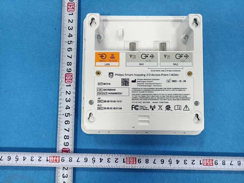
PQC-867216A
Jan 15, 2023Access Point
Equipment Class
DTS - Digital Transmission System
PQC-IITBV1
Mar 08, 20212.4G Radio Module
Equipment Class
DTS - Digital Transmission System
PQC-MX40SH1C4
Mar 31, 2014Intellivue MX40 1.4 GHz Patient Worn Device
Equipment Class
NII - Unlicensed National Information Infrastructure TX
PQC-OBRBSBV1
Nov 17, 2013CTG Base Station
Equipment Class
TNB - Licensed Non-Broadcast Station Transmitter