PQCM3814AHOME SP02 / PULSE MONITOR
Philips Medical Systems North America Co.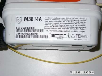
Click to zoom
Application Details
- Equipment Class
- DXX - Part 15 Low Power Communication Device Transmitter
- Date of Grant
- Jun 15, 2004
- Application Purpose
- Original Equipment
- Date of Application
- Jun 15, 2004
- Equipment Note
- HOME SP02 / PULSE MONITOR
- Frequency Range
- 916.50000000 - 916.50000000
- Country
- United States
Documents & Files
Document Text
Text extracted from the exhibit documents filed with the FCC. Open a document above to read the original.
Users Manual
Pulse Oximeter 2 Notice Proprietary Information This document contains proprietary information that is protected by copyright. Reproduction, adaptation, or translation without prior written permission is prohibited, except as allowed under the copyright laws. Philips Medical Systems 3000 Minuteman Road Andover, MA 01810-1085 (978) 687-1501 Publication number M3814-90003 Rev A Printed in USA Warranty The information contained in this document is subject to change without notice. Philips Medical Systems makes no warranty of any kind with regard to this material, including, but not limited to, the implied warranties or merchantability and fitness for a particular purpose. Philips Medical Systems shall not be liable for errors contained herein or for incidental or consequential damages in connection with the furnishing, performance, or use of this material. Printing History New editions of this document will incorporate all material updated since the previous edition. The documentation printing date and part number indicate its current edition. The printing date changes when a new edition is printed. (Minor corrections and updates which are incorporated at reprint do not cause the date to change.) The document part number changes when extensive technical changes are incorporated. Revision AAugust 2004 Copyright Copyright August 2004 Koninklijke Philips Electronics N.V. All Rights Reserved. 3 Table of Contents Introduction . . . . . . . . . . . . . . . . . . . . . . . . . . . . . . 4 WELCOME . . . . . . . . . . . . . . . . . . . . . . . . . . . . . . . . . . . . . . . . . 4 How the System Works . . . . . . . . . . . . . . . . . . . . . . . . . . . . . . . 4 Keeping the System Working . . . . . . . . . . . . . . . . . . . . . . . . . . . 4 Thank You! . . . . . . . . . . . . . . . . . . . . . . . . . . . . . . . . . . . . . . . . . 4 Safety and Precautions. . . . . . . . . . . . . . . . . . . . . . 5 Follow Instructions . . . . . . . . . . . . . . . . . . . . . . . . . . . . . . . . . . . 5 Warnings . . . . . . . . . . . . . . . . . . . . . . . . . . . . . . . . . . . . . . . . . . . 5 Cautions . . . . . . . . . . . . . . . . . . . . . . . . . . . . . . . . . . . . . . . . . . . 5 Pulse Oximeter Components . . . . . . . . . . . . . . . . 7 Measurement . . . . . . . . . . . . . . . . . . . . . . . . . . . . . 8 Maintenance . . . . . . . . . . . . . . . . . . . . . . . . . . . . . 10 Cleaning . . . . . . . . . . . . . . . . . . . . . . . . . . . . . . . . . . . . . . . . . . . 10 Storing . . . . . . . . . . . . . . . . . . . . . . . . . . . . . . . . . . . . . . . . . . . . 10 Replacing Batteries . . . . . . . . . . . . . . . . . . . . . . . . . . . . . . . . . . 11 Troubleshooting. . . . . . . . . . . . . . . . . . . . . . . . . . 12 Specifications . . . . . . . . . . . . . . . . . . . . . . . . . . . . 13 Electromagnetic Compatibility. . . . . . . . . . . . . . . 14 Electromagnetic Compatibility . . . . . . . . . . . . . . . . . . . . . . . . . 14 EMC Testing . . . . . . . . . . . . . . . . . . . . . . . . . . . . . . . . . . . . . . . 14 Avoiding Electromagnetic Interference Problems 1 . . . . . . . . . . 5 FCC Regulations . . . . . . . . . . . . . . . . . . . . . . . . . . . . . . . . . . . . 16 4 Introduction WELCOME Welcome to Philips Telemonitoring Services. This Pulse Oximeter Instructions for Use explains how to use the Pulse Oximeter to measure your blood oxygen level (%SpO 2 ) and pulse rate from the comfort and convenience of your home. It also explains how to maintain, clean, and troubleshoot the Pulse Oximeter and gives a number of safety precautions you should follow to assure safe, reliable and accurate measurements. In only a few minutes every day you can provide these measurements to your healthcare provider so that he/she can make better decisions about your care. In this way, you are providing information that can help improve your health care and quality of life. How the System Works With this system, the Pulse Oximeter measurements are immediately sent to your Home Hub or TeleStation, which then automatically transmits them over your telephone line to your healthcare provider’s computer. While the system uses your telephone to transmit the measurement, feel free to talk on you phone at any time -- the system is “smart” enough to know when the phone line is open. It will wait and then send the information after you hang up. Keeping the System Working If at any time you suspect something is wrong with the Pulse Oximeter or any part of the Telemonitoring System, immediately contact your healthcare provider. Philips will replace any defective device. You can also cross-check your results with another Pulse Oximeter if additional measurement devices of the same type are available to you. Thank You! Thank you for taking an active role in your home healthcare plan. Philips and your healthcare provider applaud your efforts to actively participate in you health care plan. 5 Safety and Precautions Safety Follow Instructions Follow your doctor’s instructions about symptoms that require you to contact your healthcare provider. This system does not take the place of medical care. Remember, only your healthcare provider is trained to interpret the results. He or she will tell you when and how often to take your vital signs. Please read all of the instructions in this guide before using the Pulse Oximeter and follow the instructions carefully. Symbols Type B Patient Applied Parts as defined in IEC 60601-1-1. Not suitable for direct cardiac application. Attention: Consult accompanying documents. Meets IEC- 60950 standards Meets Class B standards. Meets Part 15 standards. Precautions Warnings The word Warning is used for a hazard that could result in severe injury or death. Observe the following Warnings: The Pulse Oximeter is provided for your use only. •Do not let anyone else use it. •Do not swap devices with a neighbor or family member who has the same or similar system. These devices are…
Text truncated - open the document above for the full version.
Block Diagram
A A B B C C D D E E 44 33 22 1 1 Matching network RFM TR1000 Antenna in PCB etch Transmit serial stream Transmit level select (Normal/Reduced) Transmitter enable/sleep Transmit level-set components RF block diagram A1 M3814A Pulse Oximeter Main PC Board Block Diagram A 11June 14, 2004 eCare Services 3000 Minuteman Road, Andover, MA 01810 Philips CONFIDENTIAL Title SizeDocument NumberRev Date: Sheetof
External Photos
PQCM3814A External Photos Page 1 of 3 EUT Top PQCM3814A External Photos Page 2 of 3 Bottom of EUT PQCM3814A External Photos Page 3 of 3 Side of EUT (note, this is not the final/correct label, see label sample exhibit for correct)
ID Label/Location Info
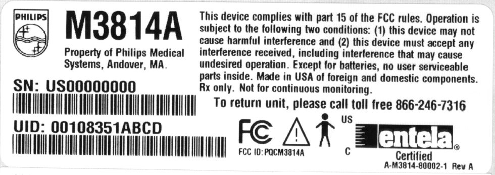
PQCM3814A Label Location Back Side of EUT (note, this is not the final/correct label, see label sample exhibit for correct)
Internal Photos
PQCM3814A Internal Photos Page 1 of 3 Board and display with cover removed PQCM3814A Internal Photos Page 2 of 3 Rear of PCB removed from EUT housing PQCM3814A Internal Photos Page 3 of 3 Inside of housing with PCB removed showing the SPO2 measurement device and battery connections.
Test Report
Compliance Worldwide, Inc. – 357 Main Street – Sandown, NH 03873 (603) 887 3903 Fax 887 6445 http://www.cw-inc.com TEST NUMBER - 250-04 TEST REPORT TO FEDERAL COMMUNICATIONS COMMISSION CFR 47 PART 15.249 Low Power License-Exempt Radio communication Devices Transmitter for Philips Medical Systems 3000 Minuteman Drive M/S 335 Andover, MA 01810 978-659-2282 of M3814A Home SPO2 device FCC ID: PQCM3814A on 5/17/2004 Tested by Andrew Mertinooke Reviewed by Clifton P. Brick This report may not be duplicated, except in full without written permission from Compliance Worldwide, Inc. Page 2 of 17 Compliance Worldwide, Inc. – 357 Main Street – Sandown, NH 03873 (603) 887 3903 Fax 887 6445 http://www.cw-inc.com TEST NUMBER - 250-04 TABLE OF CONTENTS • Test Description • Test Results and Conclusions • FCC DOC Label • Test Procedures • Part 15 Subpart B Test Limits • Test Facility Description • Test Setup and Connection Information • Test Measurements and Results Radiated Output Power & Occupied Bandwidth Radiated Measurements Conducted Measurements • Notes and Comments Page 3 of 17 Compliance Worldwide, Inc. – 357 Main Street – Sandown, NH 03873 (603) 887 3903 Fax 887 6445 http://www.cw-inc.com TEST NUMBER - 250-04 TEST DESCRIPTION 1. TEST OBJECTIVE To test the M3814A Pulse Oximeter Part 15 Subpart C Rules and write a report. 2. E.U.T. DESCRIPTION GENERAL The M3814A Pulse Oximeter M3814A is home medical monitoring device that measures SPO2 and Pulse values from the patient and transmits the data approximately 2 times per day to a home “hub” base station, that then uses the telephone lines to send the information to the physician. SERIAL NUMBERS: US00000000 Page 4 of 17 Compliance Worldwide, Inc. – 357 Main Street – Sandown, NH 03873 (603) 887 3903 Fax 887 6445 http://www.cw-inc.com TEST NUMBER - 250-04 TEST RESULTS AND CONCLUSIONS PRODUCT TESTED - Pulse Oximeter MODEL NUMBER - M3814A RADIATED TEST RESULTS The test results show that the emissions radiated from this equipment are in compliance with FCC Rules Part 15 Subpart C. OCCUPIED BANDWIDTH & OUTPUT POWER The test results show that the occupied bandwidth and output power of this equipment are in compliance with FCC Rules Part 15 Subpart B . CONDUCTED TEST RESULTS The test results show that the emissions conducted through the power line from this equipment are in compliance with FCC Rules Part 15 Subpart B. ANALYSIS AND CONCLUSIONS Based upon the radiated and conducted measurements we find that this equipment is within the limits of the FCC Rules Part 15 Subpart B. All results are based on a test of one sample, and represent other production units, only in as much as a sample represents other production units. If any significant changes are made to the unit, the changes shall be evaluated and a retest may be required. NOTES (Special conditions unique to this test) None Page 5 of 17 Compliance Worldwide, Inc. – 357 Main Street – Sandown, NH 03873 (603) 887 3903 Fax 887 6445 http://www.cw-inc.com TEST NUMBER - 250-04 TEST PROCEDURES 1. TEST EQUIPMENT A. HP 8546A (9 kHz - 6.5 GHz) EMI Receiver w/ RF Filter Section, S/N 3704A00323 / 3650A00360. Calibration Date 1-16-2004, calibrated annually. B. HP 8593E (9 kHz - 26.5 GHz) Spectrum Analyzer, S/N 3829A03887. Calibration Date 11-21-2003, calibrated annually. B. Com-Power Biconilog Antenna, Model AC220, S/N 25509. Calibration Date 7-17-2003, calibrated annually. E. Electro-Metrics Double Ridged Guide Antenna, Model EM-6961, S/N 6337. Calibration Date: 6-24-2003, calibrated annually. F. HP 1 - 26.5 GHz Preamplifier, Model 08449B, S/N 3008A01323. Calibration Date: 1-7-2004, calibrated annually. D. EMCO LISN, Model EM 3825/2, S/N 9109-1860. Calibration Date: 3-10-2004, calibrated annually. 2. FREQUENCY RANGE TO BE SCANNED. A. Radiated Test from 30 MHz to 40 GHz (or the 10 th harmonic of the highest frequency whichever is lower). B. Conducted Test from 150 kHz to 30 MHz. Page 6 of 17 Compliance Worldwide, Inc. – 357 Main Street – Sandown, NH 03873 (603) 887 3903 Fax 887 6445 http://www.cw-inc.com TEST NUMBER - 250-04 3. TEST PROCEDURES. Radiated test procedure: The EUT, associated cables and peripheral devices are placed on the supporting table and any support equipment is placed off the site. The EUT is turned on and any necessary operating or test software installed and allowed to warm up. The EUT is pre-scanned in our ferrite tile lined chamber where it is rotated 360 degrees and examined in both horizontal and vertical polarization, all emission frequencies are identified and recorded. The EUT is then moved to the OATS and the frequency band from 30 MHz to 40 GHz is scanned, all frequencies identified in the chamber are investigated as well as harmonics of the EUT. When an emission is found the emission is maximized by varying the bundle position of the connecting cables, the antenna height, the antenna polarization (vertical and horizontal) and the table orientation (360 degrees). The maximum reading is recorded and the next signal is searched for. Conducted test procedure: The power line of the EUT is connected to the LISN (Line Impedance Stabilization Network). A measurement of the emissions are made from the power line for both phase and neutral on the analyzer in the frequency range from 150 kHz to 30 MHz. The maximum readings are recorded for each phase. All measurements are made according to the procedures defined in: "ANSI C63.4-1992 Standard Methods of Measurement of Radio Noise Emissions from Low-Voltage Electrical and Electronics Equipment in the Range of 9 kHz to 40 GHz, American National Standard for (ISBN 1- 55937-215-5). Page 7 of 17 Compliance Worldwide, Inc. – 357 Main Street – Sandown, NH 03873 (603) 887 3903 Fax 887 6445 http://www.cw-inc.com TEST NUMBER - 250-04 TEST LIMITS 1. FCC Part 15 Radiation Limits (Quasi-Peak): Frequency MHz Distance meters Limit dBμV/m Limit μV/m 30 - 88 3 40.0 100 88 - 216 3 43.5 150 902 - 928 3 94.0 50,000 216 - 960 3 46.0 200 960 - 1000 3 54.0 500 1000 - 40…
Text truncated - open the document above for the full version.
Test Setup Photos
PQCM3814A Test Setup Photos Page 1 of 2 Radiated Setup Front PQCM3814A Test Setup Photos Page 2 of 2 Top/Front of EUT
Contact Information
Applicant
Delroy Smith(Principal Architect)
Test Firm
Compliance Worldwide, Inc.Robert McCall
Technical Specifications
| # | Rule Parts | Frequency Range | Power Output |
|---|---|---|---|
| 1 | 15C | 916.5 MHz - 916.5 MHz | - |
Other Applications from Philips Medical Systems North America Co.
PQC-AIM
Apr 14, 2024AIM
Equipment Class
DTS - Digital Transmission System
PQC-867216A
Jan 15, 2023Access Point
Equipment Class
DTS - Digital Transmission System
PQC-IITBV1
Mar 08, 20212.4G Radio Module
Equipment Class
DTS - Digital Transmission System
PQC-MX40SH1C4
Mar 31, 2014Intellivue MX40 1.4 GHz Patient Worn Device
Equipment Class
NII - Unlicensed National Information Infrastructure TX
PQC-OBRBSBV1
Nov 17, 2013CTG Base Station
Equipment Class
TNB - Licensed Non-Broadcast Station Transmitter