PQMASTOP2Wireless Handheld Transmitter
Caterpillar, Inc.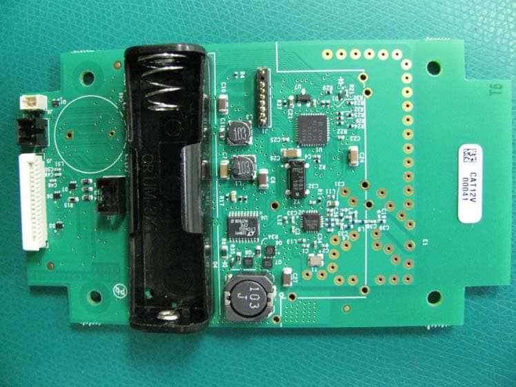
Click to zoom
Application Details
- Equipment Class
- DTS - Digital Transmission System
- Date of Grant
- Mar 27, 2012
- Application Purpose
- Original Equipment
- Date of Application
- Mar 27, 2012
- Equipment Note
- Wireless Handheld Transmitter
- Frequency Range
- 919.00000000 - 919.00000000
- Company
- Caterpillar, Inc.
- Country
- United States
Documents & Files
Document Text
Text extracted from the exhibit documents filed with the FCC. Open a document above to read the original.
Users Manual
REHS7414 18 January 2012 Special Instruction i04694729 Autonomous Stop (A-Stop) System for Autonomous Hauling SMCS Code: Off-Highway Truck/Tractor 793D (S/N: FDB1-Up) 793F (S/N: SSP1-Up; RBT1-Up) 797F (S/N: LAJ1-Up) Table of Contents Introduction ........................................................... 1 Overview ............................................................... 1 A-Stop Operation .................................................. 3 Stopping ............................................................ 4 Clearing an A-Stop ............................................ 5 Resuming Autonomous Operation .................... 5 Testing the A-Stop System ................................... 5 Electrical Input Components ................................. 5 Autonomous Stop Receivers ............................. 5 Electrical Output Components .............................. 6 A-Stop Transmitter ............................................ 6 Introduction This document contains operational information about the A-Stop System. Note:This equipment has been tested and found to comply with the limits for a Class A digital device, pursuant to part 15 of the FCC rules. These limits are designed to provide protection against harmful interference when the equipment is operated in a commercial environment. This equipment generates, uses, and can radiate radio frequency energy and, if not installed and used in accordance with the instruction manual, may cause harmful interference to radio communications. Operation of this equipment in a residential area is likely to cause harmful interference in which case the user will be required to correct the interference at their own expense. Note:Modifications not expressly approved by the manufac turer could void the user's authority to operate the equipment under FCC rules. Overview g027 99169 Illustration 1 Tabl e1 CalloutButtonDescription 1 A-Stop Button Used to transmit an A-Stop Signal received by all autonomous machines within range. The A-Stop signal will continue to transmit until the A-Stop Reset (2) is pressed. (1) (continued) 1 (Table 1, contd) Callout ButtonDescription 2 A-Stop Reset Button Used to stop transmitting the A-Stop signal. The A-Stop Reset button (2) will only stop the transmission of the A-Stop signal, this button will not clear an effected machine to resume operation. 3Clear Button Used to signal all machines in theareathat those machines can resume autonomous operation. Each transmitter that has signaled an A-stop must be pressed before the effect machine can resume operation. (2) 4Test Button Used to initiate an A-Stop system test between the transmitter and all autonomous machines in range of the transmitter. The test button (4) is amomentary switch 5 Alarm Silence Used to silence the audible alarm during an A-Stop event. 6 Battery Charge Indicators Used to show status of the transmitter battery. 7Charging Port Used to charge the transmitter. (1) Only the transmitter that sent the A-Stop signal can cancel the A-Stop command. (2) Pressing the clear button (3) does not allow the truck to resume the task it was assigned before the A-Stop was initiated. The clear button (3) only allows the truck to receive another assignment. MineStar must be used to assign an autonomous ready truck after an A-Stop event. The autonomous stop (A-Stop) system is used to stoptheautonomoustrucksintheareaincaseof emergency or un planned need. The system sends a radio signal to all the trucks within the operating range of the handheld transmitter. The communications of the A-Stop sys tem operate independently from the normal autonomy system and can be used even if MineStar cannot communicate with the truck. Each person working in the area of autonomous operation shall be issued an A-Stop transmitter and is required t o carry the transmitter at all times. g02799149 Illustration 2 Receiver Each autonomous haul truck has two receivers which operate on different data links. The receivers are powered by the machine and send out a heartbeat message to the truck under normal operation. 2 A-Stop Operation g02728442 Illustration 3 Single transmitter in operation (1) Autonomous machines with on-board A-Stop receiver Illustration 3 shows three Autonomous machines with on-board A-Stop receivers. Theflashing light on the A-Stop remote indicates that an A-Stop has been activated. The large circle in the illustration is the range of the A-Stop remote. In the illustration, the three Autonomous machines that are in range of the A-Stop remote are stopped due to the A-Stop button that was pressed. 3 g02727922 Illustration 4 Multiple transmitters in operation (1) Autonomous machines with on-board A-Stop receiver Once an A-Stop event has occurred, any machines in the range of the remote transmitter will be stopped for as long as the remote is transmitting. A “Clear” signal will need to be sent before any of the machines affected will be able to resume normal operation. When more than one remote is activated at once, all remotes that sent an A-Stop command will need to send a “Clear” signal. Refer to Illustration 4 for an example of multiple transmitters in operation at once. Stopping g02742797 Illustration 5 4 When a truck receives an A-Stop stop signal, the truck immediately initiates a controlled stop. While the truck is in a utonomous mode with A-Stop active, the autonomous mode and A-Stop lights will be flashing. Refer to Illustration 5 for an example. Clearing an A-Stop g02742856 Illustration 6 The truck identifies and records which transmitter or transmitters have initiated the A-Stop. The truck can only resume autonomous operation when an A-Stop clear message is received from all the transmitters that the truck received a stop message from. Once the truck has received a clear message from every transmitter that the truck received a stop message from, the truck will deactivate the A-Stop and the A-Stop light with stopflashing. Refer to Illustration 6 for an example. R…
Text truncated - open the document above for the full version.
External Photos
CONFIDENTIAL INFORMATION Technical Description Device Photographs - Transmitter Type: Doc No: Rev: Date: Page: Specification CAT0000736 A Feb 28, 2012 1 of 5 Device Photographs Remote Autonomous Stop System Transmitter REVISION CHANGE HISTORY APPROVALS Change Description Revision ECO Date Initial release A NE0069679 Feb 28, 2012 Approval Signature Date Benchmark Program Manager Joseph Hlavka See Electronic Sign-Off in AGILE Benchmark Electrical Engineer Larry Nielsen Benchmark Electrical Engineer Doug Lochner Benchmark Mechanical Engineer Matt Kujawa CONFIDENTIAL INFORMATION Technical Description Device Photographs - Transmitter Type: Doc No: Rev: Date: Page: Specification CAT0000736 A Feb 28, 2012 2 of 5 Photographs in this document show components of the Transmitter for the Remote Autonomous Stop System, as specified by FCC Rules, Section 2.1033(b)(5). Figure 1 – Circuit Board Assembly, top side Figure 2 – Circuit Board Assembly, back side CONFIDENTIAL INFORMATION Technical Description Device Photographs - Transmitter Type: Doc No: Rev: Date: Page: Specification CAT0000736 A Feb 28, 2012 3 of 5 Figure 3 – Circuit Board with Shield, top side Figure 4 – Circuit Board with Shield, back side CONFIDENTIAL INFORMATION Technical Description Device Photographs - Transmitter Type: Doc No: Rev: Date: Page: Specification CAT0000736 A Feb 28, 2012 4 of 5 Figure 5 – Circuit Board in Enclosure Figure 6 – Enclosure with Cover installed, and Label location LABEL LOCATION
ID Label/Location Info
CONFIDENTIAL INFORMATION Technical Description Device Photographs - Transmitter Type: Doc No: Rev: Date: Page: Specification CAT0000736 A Feb 28, 2012 5 of 5 Figure 7 – Enclosure, Front side Figure 8 – Device Label (end of document)
Internal Photos
CONFIDENTIAL INFORMATION Technical Description Device Photographs - Transmitter Type: Doc No: Rev: Date: Page: Specification CAT0000736 A Feb 28, 2012 1 of 5 Device Photographs Remote Autonomous Stop System Transmitter REVISION CHANGE HISTORY APPROVALS Change Description Revision ECO Date Initial release A NE0069679 Feb 28, 2012 Approval Signature Date Benchmark Program Manager Joseph Hlavka See Electronic Sign-Off in AGILE Benchmark Electrical Engineer Larry Nielsen Benchmark Electrical Engineer Doug Lochner Benchmark Mechanical Engineer Matt Kujawa CONFIDENTIAL INFORMATION Technical Description Device Photographs - Transmitter Type: Doc No: Rev: Date: Page: Specification CAT0000736 A Feb 28, 2012 2 of 5 Photographs in this document show components of the Transmitter for the Remote Autonomous Stop System, as specified by FCC Rules, Section 2.1033(b)(5). Figure 1 – Circuit Board Assembly, top side Figure 2 – Circuit Board Assembly, back side CONFIDENTIAL INFORMATION Technical Description Device Photographs - Transmitter Type: Doc No: Rev: Date: Page: Specification CAT0000736 A Feb 28, 2012 3 of 5 Figure 3 – Circuit Board with Shield, top side Figure 4 – Circuit Board with Shield, back side CONFIDENTIAL INFORMATION Technical Description Device Photographs - Transmitter Type: Doc No: Rev: Date: Page: Specification CAT0000736 A Feb 28, 2012 4 of 5 Figure 5 – Circuit Board in Enclosure Figure 6 – Enclosure with Cover installed, and Label location LABEL LOCATION
Test Report
TEST REPORT Report Number: 100586460MIN-001 Project Number: G100586460 Testing performed on the CAT0000433 FCC ID: PQMASTOP2 Industry Canada ID: 4071-ASTOP2 to 47 CFR Part 15. 247:2010 RSS- 210, Issue 8, 2010 47 CFR, Part 15:2009, §15.107 and §15.109, Class B ICES-003, Issue 4:2004 AS/NZS 4268:2008 For Benchmark Electronics, Inc. Test Performed by: Test Authorized by: Intertek Testing Services NA, Inc. 7250 Hudson Blvd., Suite 100 Oakdale, MN 55128 USA Benchmark Electronics, Inc. 3535 Technology Drive Rochester, MN 55901, USA Prepared by: Date: February 29, 2012 Richard Blonigen Reviewed by: Date: February 29, 2012 Norman Shpilsher This report is for the exclusive use of Intertek's Client and is provided pursuant to the agreement between Intertek and its Client. Intertek's responsibility and liability are limited to the terms and conditions of the agreement. Intertek assumes no liability to any party, other than to the Client in accordance with the agreement, for any loss, expense or damage occasioned by the use of this report. Only the Client is authorized to copy or distribute this report and then only in its entirety. Any use of the Intertek name or one of its marks for the sale or advertisement of the tested material, product or service must first be approved in writing by Intertek. The observations and test results in this report are relevant only to the sample tested. This report by itself does not imply that the material, product, or service is or has ever been under an Intertek certification program. This report must not be used to claim product endorsement by A2LA, NIST nor any other agency of the U.S. Government. EMC Report No: 100586460MIN-001 FCC ID: PQMASTOP2 IC ID: 4071-ASTOP2 Page 2 of 31 TABLE OF CONTENTS 1.0 GENERAL DESCRIPTION..........................................................................................................3 1.1 Product Description; Test Facility......................................................................................4 1.3 Environmental conditions ..................................................................................................5 1.4 Measurement uncertainty..................................................................................................6 1.5 Field Strength Calculation .................................................................................................6 2.0 TEST SUMMARY..........................................................................................................................7 3.0 TEST CONDITIONS AND RESULTS........................................................................................8 3.1 Maximum peak output power ............................................................................................8 3.2 6dB bandwidth of the digital modulation .........................................................................10 3.3 Power spectral density ....................................................................................................12 3.4 Antenna conducted spurious emissions..........................................................................14 3.5 Radiated spurious emissions ..........................................................................................17 3.6 RF Exposure Compliance ...............................................................................................20 3.7 Transmitter power line conducted emissions ..................................................................21 3.8 Receiver/digital device radiated emissions .....................................................................24 3.9 Digital device conducted emissions ................................................................................28 4.0 TEST EQUIPMENT.....................................................................................................................31 EMC Report No: 100586460MIN-001 FCC ID: PQMASTOP2 IC ID: 4071-ASTOP2 Page 3 of 31 1.0 GENERAL DESCRIPTION Model: CAT0000433 Type of EUT: Remote Autonomous Stop Serial Number: 00002-12F (continuous transmitting sample) 00003-12F (normal operating mode sample) FCC ID: PQMASTOP2 Industry Canada ID: 4071-ASTOP2 Related Submittal(s) Grants: None Company: Benchmark Electronics, Inc. Customer: Mr. Joeseph Hlavka Address: 3535 Technology Drive Rochester, MN 55901, USA Phone: (507) 535-4265 Fax: (507) 535-4828 e-mail: [email protected] Test Standards: 47 CFR, Part 15:2010, §15.247 RSS–210, Issue 8, 2010 RSS-Gen, Issue 3, 2010 47 CFR, Part 15:2010, §15.107 and §15.109, Class B ICES-003, Issue 4:2004 AS/NZS 4268:2008 Type of radio: Stand -alone Module Hybrid Date Sample Submitted: January 3, 2012 Test Work Started: January 3, 2012 Test Work Completed: January 4, 2012 Test Sample Conditions: Damaged Poor (Usable) Good EMC Report No: 100586460MIN-001 FCC ID: PQMASTOP2 IC ID: 4071-ASTOP2 Page 4 of 31 1.1 Product Description; Test Facility Product Description: 919MHz Transceiver Transmitter Type: FHSS Digital Modulation WiFi Blue Tooth Operating Frequency Range(s): 919MHz Number of Channels: 1 Modulation: 2-FSK Emission Designator: 570KFIDBN Antenna(s) Info: Integral Antenna Antenna Gain: -1dBi Antenna Installation: User Professional Factory Transmitter power configuration: Internal battery External power source 100-240VAC 230VAC 400VAC VDC Other: 0.4 Amp. 50/60Hz 60Hz Special Test Arrangement: None Test Facility Accreditation: A2LA (Certificate No. 1427.01) Test Methodology: Measurements performed according to the procedures in ANSI C63.10- 2009 and FCC DTS Measurement Guide EMC Report No: 100586460MIN-001 FCC ID: PQMASTOP2 IC ID: 4071-ASTOP2 Page 5 of 31 1.2 EUT Configuration The equipment under test was operated during the measurement under the following conditions: - Standby - Continuous transmissions (modulated signal) - Continuous transmissions (un-modulated signal) - Continuous receiving - Test program (customer specific) - Operating modes of the EUT: No. Description 1 Test …
Text truncated - open the document above for the full version.
Test Setup Photos
Test Setup Photos
Contact Information
Applicant
Wesley D Breedlove(Certification Engineer)
Test Firm
Intertek Testing Services NA, Inc.Andrew Waytulonis
Technical Specifications
| # | Rule Parts | Frequency Range | Power Output |
|---|---|---|---|
| 1 | 15C | 919 MHz - 919 MHz | 16.00 mW |
Other Applications from Caterpillar, Inc.
PQMCRM02
Dec 11, 2022RADIO BOX
Equipment Class
DSS - Part 15 Spread Spectrum Transmitter
PQMTWS
May 21, 2020Caterpillar Trackwear Sensor
Equipment Class
DTS - Digital Transmission System
PQMMSS3I
Sep 15, 2015Caterpillar MSS3i RFID Key Reader Module
Equipment Class
DCD - Part 15 Low Power Transmitter Below 1705 kHz
PQMASTOP1
Mar 27, 2012Wireless Onboard Transceiver
Equipment Class
DTS - Digital Transmission System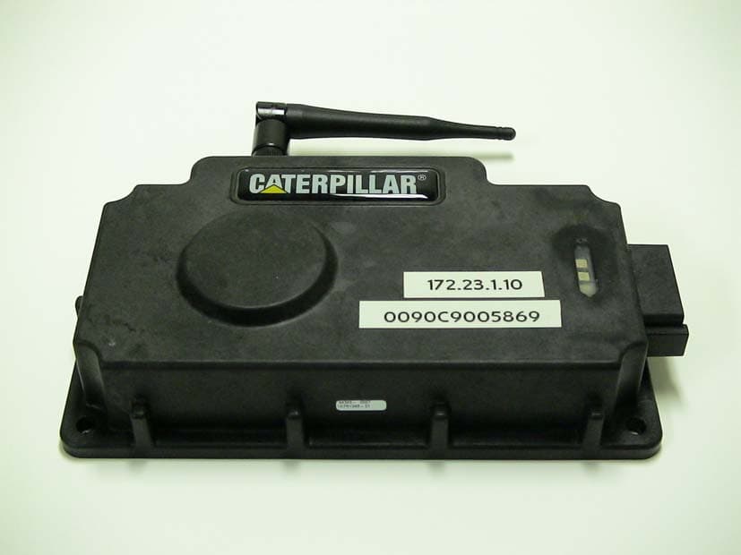
PQMWCA1
Jan 05, 2005Wireless Communication Adapter
Equipment Class
DTS - Digital Transmission System