PQMWCA1Wireless Communication Adapter
Caterpillar, Inc.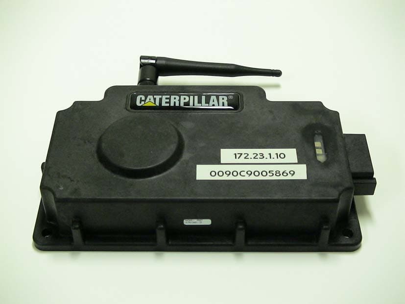
Click to zoom
Application Details
- Equipment Class
- DTS - Digital Transmission System
- Date of Grant
- Jan 05, 2005
- Application Purpose
- Original Equipment
- Date of Application
- Jan 05, 2005
- Equipment Note
- Wireless Communication Adapter
- Frequency Range
- 2412.00000000 - 2462.00000000
- Company
- Caterpillar, Inc.
- Country
- United States
Documents & Files
Document Text
Text extracted from the exhibit documents filed with the FCC. Open a document above to read the original.
Users Manual
Using the 261-3363 Wireless Communication Adapter SMCS: 1900 TOOL OPERATING MANUAL R TOOL OPERATING MANUAL NEHS0926-01 January 2005 Important Safety Information Think Safety Most accidents that involve product operation, maintenance, and repair are caused by failure to observe basic safety rules or precautions. An accident can often be avoided by recognizing potentially hazardous situations before an accident occurs. A person must be alert to potential hazards. This person should also have the necessary training, skills, and tools to perform these functions properly. Improper operation, lubrication, maintenance, or repair of this product can be dangerous and could result in injury or death. Do not operate or perform any lubrication, maintenance, or repair on this product until you have read and understood the operation, lubrication, maintenance, and repair information. Safety precautions and warnings are provided in this manual and on the product. If these hazard warnings are not heeded, bodily injury or death could occur to you or to other persons. The hazards are identified by the “Safety Alert Symbol” and followed by a “Signal Word” such as “DANGER”, “WARNING”, or “CAUTION”. The Safety Alert “WARNING” label is shown below. The meaning of this safety alert symbol is as follows: Attention! Become Alert! Your Safety is Involved. The message that appears under the warning explains the hazard and can be either written or pictorially presented. Operations that may cause product damage are identified by “NOTICE” labels on the product and in this publication. Caterpillar cannot anticipate every possible circumstance that might involve a potential hazard. The warnings in this publication and on the product are, therefore, not all inclusive. If a tool, procedure, work method, or operating technique that is not specifically recommended by Caterpillar is not used, you must satisfy yourself that it is safe for you and for others. You should also ensure that the product will not be damaged or be made unsafe by the operation, lubrication, maintenance or repair procedures that you choose. The information, specifications, and illustrations in this publication are on the basis of information that was available at the time that the publication was written. The specifications, torques, pressures, measurements, adjustments, illustrations, and other items can change at any time. These changes can affect the service that is given to the product. Obtain the complete and most current information before you start any job. When replacement parts are required for this product, Caterpillar recommends using Caterpillar replacement parts or parts with equivalent specifications including, but not limited to, physical dimensions, type, strength, and material. Failure to heed this warning can lead to premature failures, product damage, personal injury, or death. WARNING WARNING 2 Contents System Overview . . . . . . . . . . . . . . . . . . . . . . 4 Product Description . . . . . . . . . . . . . . . . . . 4 Wireless Communication Adapter . . . . . . . 4 Data Link Harness . . . . . . . . . . . . . . . . . . . 4 802.11b Enabled PC . . . . . . . . . . . . . . . . . 4 Network Interface. . . . . . . . . . . . . . . . . . . . 5 Parts List . . . . . . . . . . . . . . . . . . . . . . . . . . . . 5 Optional Accessories. . . . . . . . . . . . . . . . . 5 System Requirements . . . . . . . . . . . . . . . . 5 Recommended PC Configuration . . . . . . . 5 Minimum Software Requirements . . . . . . . 5 Network Requirements . . . . . . . . . . . . . . . 5 Specifications. . . . . . . . . . . . . . . . . . . . . . . 5 Operating Instructions . . . . . . . . . . . . . . . . . . 6 Software Installation . . . . . . . . . . . . . . . . . . . . 6 Windows XP Operating System . . . . . . . . . 7 Required Hardware and Software . . . . . 7 Software Installation . . . . . . . . . . . . . . . . 8 Windows 2000 Operating System . . . . . . 16 Required Hardware and Software . . . . 16 Software Installation . . . . . . . . . . . . . . . 17 Configure Cat Electronic Technician for the Wireless Communication Adapter . . . . . . . . 25 Using the Wireless Communication . . . . . . 28 Adapter Troubleshooting . . . . . . . . . . . . . . . . . . . . . . 30 General Troubleshooting Information . . . 30 Service Tools . . . . . . . . . . . . . . . . . . . . . . 30 Diagnostic Procedures . . . . . . . . . . . . . . 30 Troubleshooting with Error Codes . . . . . . 31 Troubleshooting Symptoms . . . . . . . . . . . 32 Contact Information The IP address is printed on each Wireless Communication Adapter. If the factory default IP Address on the Wireless Communication Adapter has been changed, or for any other software issues, contact Product Support: Illinois - (800) 541-8665 Outside Illinois - (800) 542-8665 Canada - (800) 523-8665 Fax: 1-309-494-1475 [email protected] 3 System Overview Product Description The 261-3363 Wireless Communication Adapter (WCA) is a service tool for remotely monitoring machine or engine operation using CatET and an 802.11 enabled PC. The group consists of a portable hardware adapter and a software program designed to run under Microsoft Windows (XP, 2000, ME, or 98). It will allow a laptop computer (PC) to aid in the monitoring of ECM communication (3) on J1939/11 high speed data link, CAT DataLink, and J1708 (ATA) vehicle networks. Communication between the Wireless Communication Adapter (2) and the PC with CatET (1) is transmitted through an 802.11b wireless network. The 261-3363 Wireless Communication Adapter is available as a group that contains all the necessary cables and software required for using the Wireless Communication Adapter on Caterpillar products. Replacement parts can also be purchased separately. For a list of the parts contained in the group, refer to the Parts List section. 1. Laptop computer with Cat Electronic Technician (CatET). 2. 802.11b wireless network. 3. Wireless Communication Adapter. 4. ECM. Wireless Communica…
Text truncated - open the document above for the full version.
Block Diagram
CAT WiCom WLAN RADIO 802.11b 2.4 GHz Digital Circuitry Antenna Automobile Interface and Power Connector 10 MHz XTAL
Block Diagram
Airborne WLN Block Diagram 802.11b Radio 36-pin Connector Embedded Microcontroller 128Kx8 SRAM 512Kx8 Flash U.FL 32.768 KHz 4.8 MHz 32.768 KHz 44 MHz 4.8 GHz A/B U.FL
Cover Letter(s)
Re: Certification for Caterpillar 239-9955 Transmitter Model: 239-9955 FCC ID: PQMWCA1 IC: 4071A-WCA1 POWER OF ATTORNEY A letter granting Valdis V. Liepa the Power of Attorney is on file and can be provided when so requested. Re: Certification for Caterpillar 239-9955 Transmitter Model: 239-9955 FCC ID: PQMWCA1 IC: 4071A-WCA1 REQUEST FOR CONFIDENTIALITY Pursuant to 47 CRF 0.459, Caterpillar requests that a part of the subject application be held confidential. This comprises Exhibits (5) Schematics (10) Parts List (Part of Exhibit only) Caterpillar has spent substantial effort in developing this product and it is one of the first of its kind in industry. Having the subject information easily available to "competition" would negate the advantage they have achieved by developing this product. Not protecting the details of the design will result in financial hardship. If there are any questions regarding this request, please contact me at the above address or call 734-483-4211, fax 734-647-2106 or e-mail [email protected]. Sincerely, Valdis V. Liepa Research Scientist University of Michigan December 26, 2004 Re: Certification for Caterpillar 239-9955 Transmitter Model: 239-9955 FCC ID: PQMWCA1 IC: 4071A-WCA1 STATEMENT OF MODIFICATIONS There were no modifications made to the DUT by this test laboratory. (Also see Section 3.1 of the attached Test Report). _____________________ Valdis V. Liepa Research Scientist Re: Certification for Caterpillar 239-9955 Transmitter Model: 239-9955 FCC ID: PQMWCA1 IC: 4071A-WCA1 GENERAL PRODUCT INFORMATION The device, for which certification is pursued, has been designed by: Caterpillar, Inc. 8201 N. University St. Peoria, IL 61615 Bill Lusa Tel: 734-484-1387 Fax: 734-484-1389 It will be manufactured by: Caterpillar, Inc. EEBU 7915 N. Hale Avenue Peoria, IL 61615 Bill Lusa Tel: 734-484-1387 Fax: 734-484-1389 Canadian Contact: Canada Industry Manager 1601 Airport Road N.E. Suite 710 Calgary, Alberta 72E 8W3 Daniel F. Harms 403-717-3853 403-717-3867
Cover Letter(s)
January 5, 2005 RE: Caterpillar, Inc. FCC ID: PQMWCA1 The following is in response to comments made on the above application. 1) Equipment type on the 731 form should be DTS. The 731 form has been updated and uploaded. 2) Please list the maximum conducted power on the 731 (also see 6 and 7 below). The 731 form has been updated and uploaded. 3) The users manual mentions a range extender antenna. However, testing was only done for one antenna. Please explain as the additional antenna is not covered by this application. The extended range antenna works with the host PC, not with the DUT in question. Thus, while it is subject to certification with host’s PCMCIA radio, it is not part of the DUT herein. 4) Please explain the use of 12 channels.....Most 802.11 devices are only approved for 11 channels in the U.S. and Canada. If this device can use more than 11 channels in other areas of the world, please explain compliance to 15.15 for the U.S. and Canada Versions. This is a typographical error in the test report. The radios provided to the manufacturer are enabled only for 11 US channels. So as to demonstrate compliance to the FCC limits, we elected to test low, middle, and high channels 2412, 2437, and 2462 MHz (channels 1, 6 and 11). The test report has been corrected. 5) Section 5 of the report mentions the digital device portion of the device is exempt. FCC policy has typically been this exemption applies only to devices that are mounted in such a way that they are part of the vehicle. Devices that are not mounted have typically not been allowed under this exemption. Please provide further information regarding this device being allowed under this exemption or the digital device data. Since the DUT is not permanently mounted to the vehicle, we now see there may be some question as to the digital device exemption. In the test report, Section 5.2 stated that no outdoor measurements were made. However, the DUT was measured for digital emissions on the OATS (see test setup photos as originally uploaded) and it meets the Class B limits by > 20 dB. Since no emissions within 20 dB of the FCC Class B limit were identified, no data was taken during testing. The test report has been updated, stating the device compliance with the FCC Class B limits. 6) It appears that average power instead of peak power was measured. If so, then the guidance document (see attached) should be followed for average measurements. Alternatively peak power measurements may be provided. In section 6.3, the test report describes that peak conducted output power was measured via the crystal detector method. 7) If average power measurements are provided, then the limits for section 6.6 become 30 dB instead of 20 dB. Please review/correct as necessary. Note that the lower bandedge only shows 20.6 dB margin at 2.4 GHz. Peak output power measurements were provided. 8) Given the bandedge plots and the high side lobe around 2.385 MHz, the output power, antenna gain, etc., it is uncertain how the side lobe at 2.385 GHz meets the 54 dBuV/m limits. Also the data only appears to be measured at 2.39 GHz. It may be possible that the plots shown are overloading the spectrum analyzer, as the fundamental to sidelobe are only around 35 dB. Note that most 802.11 devices have > 50 dB rejection at the sidelobes. Please provide better data/information to support compliance in the restricted band occurring < 2.39 GHz. Also please note that even if this result appears to be marginal, any range extending antenna may be likely to be out of compliance. Measurements must be made on the highest point . While data table 5.1 lists the emissions at 2390 MHz, this is done simply to demonstrate the worst case emission in the restricted band in question; in this case 2310-2390 MHz. Higher emissions are generally, but not always at 2390 MHz, and as such our data table reflects this. Emissions were measured for compliance over the entire band. Also, please note that the bandedge plots of figure 6.3 are measured as “peak” conducted emissions in a 100 kHz RBW, 300 kHz VBW, while the data demonstrating restricted band compliance in table 5.1 are measured as “average” radiated emissions with 1 MHz RBW, 100 Hz VBW. Thus, the bandedge data in figure 6.3 does not reflect the spectral roll off of the DUT antenna or the average radiated power of the system in the restricted band in question, and cannot be directly related to compliance with restricted band radiated emission limits. Furthermore, the emissions in figure 6.3 are not the result of saturating the spectrum analyzer input. An external 20 dB attenuator was used (see figure 6.3) and the peak output power of the radio was measured to be no more than 13 dBm. 9) REL Listing letter for IC portion of the application appears to be missing. The letter is being provided.
Cover Letter(s)
American Telecommunications Certification Body Inc. 6731 Whittier Ave, McLean, VA 22101 January 3, 2005 RE: Caterpillar, Inc. FCC ID: PQMWCA1 After a review of the submitted information, I have a few comments on the above referenced Application. 1) Equipment type on the 731 form should be DTS. 2) Please list the maximum conducted power on the 731 (also see 6 and 7 below). 3) The users manual mentions a range extender antenna. However, testing was only done for one antenna. Please explain as the additional antenna is not covered by this application. 4) Please explain the use of 12 channels.....Most 802.11 devices are only approved for 11 channels in the U.S. and Canada. If this device can use more than 11 channels in other areas of the world, please explain compliance to 15.15 for the U.S. and Canada Versions. 5) Section 5 of the report mentions the digital device portion of the device is exempt. FCC policy has typically been this exemption applies only to devices that are mounted in such a way that they are part of the vehicle. Devices that are not mounted have typically not been allowed under this exemption. Please provide further information regarding this device being allowed under this exemption or the digital device data. 6) It appears that average power instead of peak power was measured. If so, then the guidance document (see attached) should be followed for average measurements. Alternatively peak power measurements may be provided. 7) If average power measurements are provided, then the limits for section 6.6 become 30 dB instead of 20 dB. Please review/correct as necessary. Note that the lower bandedge only shows 20.6 dB margin at 2.4 GHz. 8) Given the bandedge plots and the high side lobe around 2.385 MHz, the output power, antenna gain, etc., it is uncertain how the side lobe at 2.385 GHz meets the 54 dBuV/m limits. Also the data only appears to be measured at 2.39 GHz. It may be possible that the plots shown are overloading the spectrum analyzer, as the fundamental to sidelobe are only around 35 dB. Note that most 802.11 devices have > 50 dB rejection at the sidelobes. Please provide better data/information to support compliance in the restricted band occurring < 2.39 GHz. Also please note that even if this result appears to be marginal, any range extending antenna may be likely to be out of compliance. Measurements must be made on the highest point . 9) REL Listing letter for IC portion of the application appears to be missing. Timothy R. Johnson Examining Engineer mailto: [email protected] The items indicated above must be submitted before processing can continue on the above referenced application. Failure to provide the requested information may result in application termination. Correspondence should be considered part of the permanent submission and may be viewed from the Internet after a Grant of Equipment Authorization is issued. z Page 2 January 3, 2005 Please do not respond to this correspondence using the email reply button. In order for your response to be processed expeditiously, you must submit your documents through the AmericanTCB.com website. Also, please note that partial responses increase processing time and should not be submitted. Any questions about the content of this correspondence should be directed to the sender.
Operational Description
Description of Caterpillar p/n 239-9955 (WiFi Comm Adapter) The Caterpillar 239-9955, commonly referred to as the WiFi, or Wireless Comm Adapter (WCA) is an off- board device intended to facilitate communications between off-board diagnostic tools (such as Electronic Technician (ET)), and Caterpillar Electronic Control Modules (ECMs) installed on earthmoving and construction equipment and engines. The off-board tools reside on a service technician’s laptop computer. For many years the service technician has used a “wired” Communications Adapter to connect his computer to the ECMs to perform troubleshooting, check on the health of the system, monitor data (such as engine speed, oil pressure, etc.), or flash new software. Since Caterpillar ECMs typically support at least two datalink formats on each control (one for interfacing with generic troubleshooting tools and industry-standard components, and one for proprietary communications with other Cat ECMs and diagnostic tools), and these are different for over-the-road truck engines compared to earthmoving machines, the Communications Adapter had the ability to translate messages to and from a total of three datalink formats. These are CDL (Cat Data Link), J1939, and ATA (also known as SAE J1708). The WCA performs this exact same function in allowing a laptop computer to communicate with Caterpillar ECMs, but the “wired” connection to the Service Port is now replaced with an 802.11 wireless connection. This allows the service technician more flexibility and gives him more options. The 802.11 format is well-suited for this application because the max. bandwidth (max. 11 Mb/s) is much greater than the fastest of the three datalinks (J1939 is 250Kb/s), and it has a suitable communications range (1,000 ft. max.). The WCA functions as a slave to both the ECM, and the 802.11 connection in that it only translates messages between the two, it does not initiate any communications activity, nor any other tasks.
RF Exposure Info
Potential Health Hazard EM Radiation Level The following table summarizes the minimum separation distance as calculated following FCC OET Bulletin 65. To obtain the minimum separation distance, the antenna gain (dBi) listed in Table 3.2 must be added to the radio peak output power (dBm) listed in Table 6.2 (below), resulting in the total EIRP for a given system. This EIRP is then used to compute the power density at a distance of 20 cm. S(mW/cm 2 ) = (20 mW * 1.26) / (4 π 20 2 ) = 0.005 mW/cm 2 The following equations were used in calculating the operating distance (R). 10 )( 10)()( dBGain mWPomWEIRP⋅= and 2 2 4 )( )/( R mWEIRP cmmWS ⋅Π⋅ =, R = 20 cm
Test Report
1 The University of Michigan Radiation Laboratory 3228 EECS Building Ann Arbor, MI 48109-2122 Tel: (734) 764-0500 Measured Radio Frequency Emissions From Caterpillar, Inc. WiComm Model: 239-9955 Report No. 227 January 5, 2005 Copyright © 2005 For: Caterpillar, Inc. 8201 N. University St. Peoria, IL 61615 Contact: Bill Lusa Tel: (734) 484-1387 Fax: 734-484-1389 PO: Verbal Tests supervised by: Measurements made by: Report approved by: ____________________ Joseph D. Brunett Valdis V. Liepa Research Scientist ______________________________________________________________________________ Summary Tests for compliance with FCC Regulations, Part 15.247, and with Industry Canada Regulations, RSS-210, Section 6.2.2 (o), were performed on Caterpillar, Inc. spread spectrum RF Wireless Communication device. The DUT is subject to the Rules and Regulations as a Digital Spread Spectrum transmitter. In testing completed on November 8, 2004, worst case radiated emissions in the restricted bands were met by 6.8 dB at a frequency of 2483.5 MHz (see p. 9). The DUT meets the FCC Class B digital emissions limits by greater than 20 dB. Power supply conducted emissions do not apply as the DUT is powered from a 12 VDC automotive system. 2 Introduction Caterpillar, Inc. Model 239-9955 was tested for compliance with FCC Regulations, Part 15, adopted under Docket 87-389, April 18, 1989, and with Industry Canada RSS-210, Issue 5, November, 2001. The tests were performed at the University of Michigan Radiation Laboratory Willow Run Test Range following the procedures described in ANSI C63.4-1992 "Methods of Measurement of Radio-Noise Emissions from Low-Voltage Electrical and Electronic Equipment in the Range of 9 kHz to 40 GHz". The Site description and attenuation characteristics of the Open Site facility are on file with FCC Laboratory, Columbia, Maryland (FCC Reg. No: 91050) and with Industry Canada, Ottawa, ON (File Ref. No: IC 2057). 1. Test Procedure and Equipment Used The test equipment commonly used in our facility is listed in Table 2.1 below. The HP 8593E spectrum analyzer is used for primary amplitude and frequency reference. Table 2.1 Test Equipment Test Instrument Eqpt. Used Manufacturer/Model Spectrum Analyzer (0.1-1500 MHz) Hewlett-Packard, 182T/8558B Spectrum Analyzer (9kHz-22GHz) X Hewlett-Packard 8593A SN: 3107A01358 Spectrum Analyzer (9kHz-26GHz) X Hewlett-Packard 8593E, SN: 3412A01131 Spectrum Analyzer (9kHz-26GHz) Hewlett-Packard 8563E, SN: 3310A01174 Spectrum Analyzer (9kHz-40GHz) Hewlett-Packard 8564E, SN: 3745A01031 Power Meter X Hewlett-Packard, 432A Power Meter Anritsu, ML4803A/MP Peak Power Meter X Pacific Instruments 1018B Harmonic Mixer (26-40 GHz) Hewlett-Packard 11970A, SN: 3003A08327 Harmonic Mixer (40-60 GHz) Hewlett-Packard 11970U, SN: 2332A00500 Harmonic Mixer (75-110 GHz) Hewlett-Packard 11970W, SN: 2521A00179 Harmonic Mixer (140-220 GHz) Pacific Millimeter Prod., GMA, SN: 26 S-Band Std. Gain Horn X S/A, Model SGH-2.6 C-Band Std. Gain Horn X University of Michigan, NRL design XN-Band Std. Gain Horn X University of Michigan, NRL design X-Band Std. Gain Horn X S/A, Model 12-8.2 X-band horn (8.2- 12.4 GHz) X Narda 640 X-band horn (8.2- 12.4 GHz) Scientific Atlanta , 12-8.2, SN: 730 K-band horn (18-26.5 GHz) X FXR, Inc., K638KF Ka-band horn (26.5-40 GHz) X FXR, Inc., U638A U-band horn (40-60 GHz) Custom Microwave, HO19 W-band horn(75-110 GHz) Custom Microwave, HO10 G-band horn (140-220 GHz) Custom Microwave, HO5R Bicone Antenna (30-250 MHz) X University of Michigan, RLBC-1 Bicone Antenna (200-1000 MHz) X University of Michigan, RLBC-2 Dipole Antenna Set (30-1000 MHz) X University of Michigan, RLDP-1,-2,-3 Dipole Antenna Set (30-1000 MHz) EMCO 2131C, SN: 992 Active Rod Antenna (30 Hz-50 MHz) EMCO 3301B, SN: 3223 Active Loop Antenna (30 Hz-50 MHz) EMCO 6502, SN:2855 Ridge-horn Antenna (300-5000 MHz) X University of Michigan Amplifier (5-1000 MHz) X Avantek, A11-1, A25-1S Amplifier (5-4500 MHz) X Avantek Amplifier (4.5-13 GHz) X Avantek, AFT-12665 Amplifier (6-16 GHz) X Trek Amplifier (16-26 GHz) X Avantek LISN Box University of Michigan Signal Generator Hewlett-Packard 8657B 3 2. Configuration and Identification of Device Under Test The DUT is a spread spectrum RF wireless link operating in 2400 - 2483.5 MHz band. The DUT consists of single WiComm unit with a monopole antenna connected to the device via an R-TNC connector. The system has been designed to operate with up to 11 channels from 2412 to 2462 MHz. The DUT was designed and manufactured by Caterpillar, 8201 N. University St., Peoria, IL 61615. Figure 3.1 shows the block diagram of the basic system. It is identified as: Caterpillar, Inc. Model(s): 239-9955 SN(s): 3424B043LP FCC ID: PQMWCA1 IC: 4071A-WCA1 With components evaluated: Radio DPAC Technologies AIRBORNE WLN MODULE Model: WLNB-AN-DP101 Cables No cable was attached between the antenna and the DUT for radiated emission testing. The antenna was directly affixed to the DUT using an R-TNC connector. A 0.3m coaxial cable with R-TNC adaptor used to conducted emissions testing. Loss accounted for in reported measurements. Antennas Table 3.2 Antennas Antenna Model Type Construction Gain (dBi) Used in Testing Monopole OMNI whip/monopole 1 X 2.1 EMI Relevant Modifications No modifications were made to the DUT in the course of testing. 3. Emission Limits 3.1 Radiated Emission Limits Since the DUT is a spread spectrum device (15.247, 2.4 GHz), the radiated emissions are subject to emissions in restricted bands (15.205). The applicable frequencies, through ten harmonics, are given below in Table 4.1. Emission limits from digital circuitry are specified in Table 4.2. 4 Table 4.1 Radiated Emission Limits (FCC:15.205; IC:RSS-210, 6.3) - Transmitter Fundamental Spurious* Frequency Ave. E lim (3m) Ave. E lim (3m) (MHz) (μV/m) dB (μV/m) (μV/m) dB (μV/m) 2400-2483.5 --- --- 2310-2390 Restricted 500 54.0 2483.5-2500 Bands 4500-5250 Bands 7250-7750 500 54.0 14470-14500 17700-21400 Restricted 220…
Text truncated - open the document above for the full version.
Contact Information
Applicant
Wesley D Breedlove(Certification Engineer)
Technical Contact
University of Michigan/EECSValdis V Liepa
[email protected]734-483-4211
1301 Beal Ave. · Ann Arbor, Michigan · United States
Non-Technical Contact
University of Michigan/EECSValdis V Liepa
[email protected]734-483-4211
Test Firm
University of MichiganValdis Liepa
Technical Specifications
| # | Rule Parts | Frequency Range | Power Output |
|---|---|---|---|
| 1 | 15C | 2.41 GHz - 2.46 GHz | 20.00 mW |
Other Applications from Caterpillar, Inc.
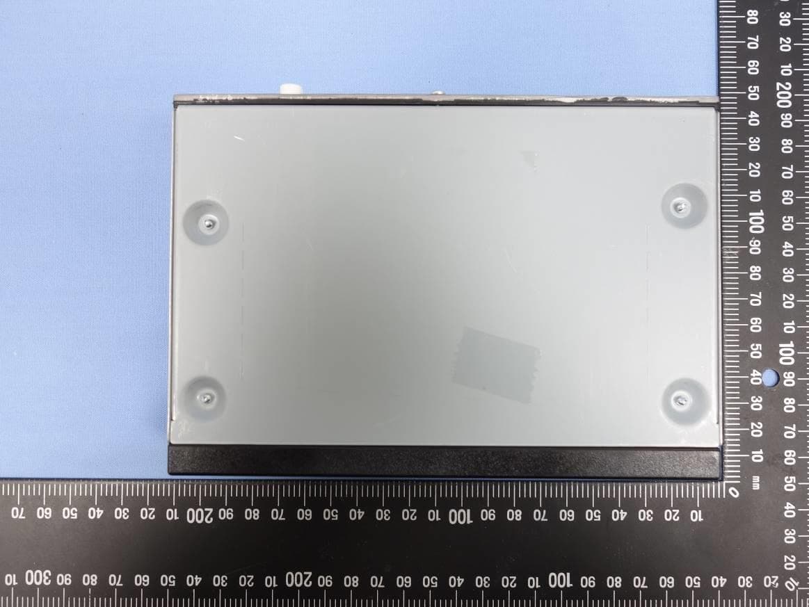
PQMCRM02
Dec 11, 2022RADIO BOX
Equipment Class
DSS - Part 15 Spread Spectrum Transmitter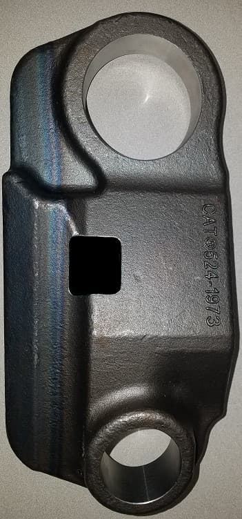
PQMTWS
May 21, 2020Caterpillar Trackwear Sensor
Equipment Class
DTS - Digital Transmission System
PQMMSS3I
Sep 15, 2015Caterpillar MSS3i RFID Key Reader Module
Equipment Class
DCD - Part 15 Low Power Transmitter Below 1705 kHz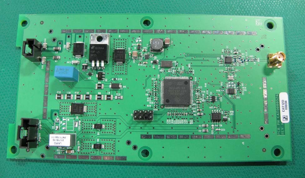
PQMASTOP1
Mar 27, 2012Wireless Onboard Transceiver
Equipment Class
DTS - Digital Transmission System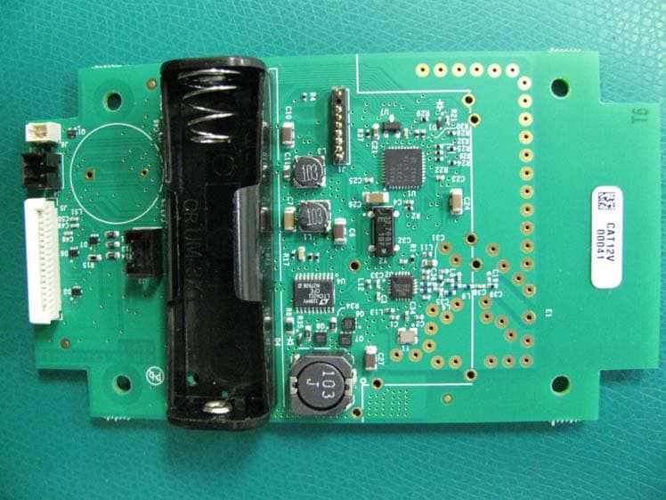
PQMASTOP2
Mar 27, 2012Wireless Handheld Transmitter
Equipment Class
DTS - Digital Transmission System