PQMMSS1Remote Key
Caterpillar, Inc.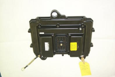
Click to zoom
Application Details
- Equipment Class
- DCD - Part 15 Low Power Transmitter Below 1705 kHz
- Date of Grant
- Sep 04, 2001
- Application Purpose
- Original Equipment
- Date of Application
- Aug 26, 2001
- Equipment Note
- Remote Key
- Frequency Range
- 0.13200000 - 0.13400000
- Company
- Caterpillar, Inc.
- Country
- United States
Documents & Files
Document Text
Text extracted from the exhibit documents filed with the FCC. Open a document above to read the original.
Users Manual
Re: Certification for Caterpillar MSS Immobilizer Model: 156-6155 FCC ID: PQMMSS1 CANADA: to be provided by IC USER'S MANUAL INFORMATION (PRELIMINARY) The User's Manual is in preparation. The following material will be contained in the manual: FCC ID: PQMMSS1 CANADA: to be provided by IC This device complies with Part 15 of the FCC Rules and with RSS-210 of Industry Canada. Operation is subject to the following two conditions: (1) This device may not cause harmful interference, and (2) This device must accept any interference received, including interference that may cause undesired operation. WARNING: Changes or modifications not expressively approved by the party responsible for compliance could void the user's authority to operate the equipment.
External Photos
Caterpillar MSS coil & casting Caterpillar MSS control module
ID Label/Location Info
Proposed Regulatory Marking Label for Caterpillar Machine Security System FCC ID: PQMMSS1 CANADA: XXXXXXXXXX
Internal Photos
Caterpillar MSS control module (open) Caterpillar MSS PCB (top) Caterpillar MSS PCB (bottom)
Test Report
Caterpillar, Inc. Page 1 of 40 EMC – Machine Security System (MSS) EMC Testing, Inc Report - MSS.doc 07/17/01 Test Report No: 01-11-35005/499 Electromagnetic Compatibility Of A Machine Security System (MSS) 156-6155 Caterpillar, Inc. Page 3 of 40 EMC – Machine Security System (MSS) EMC Testing, Inc Report - MSS.doc 07/17/01 Contents 1 Basic System Description ................................................................................. 4 2 Theory of Operation .......................................................................................... 4 3 Test Procedure and Equipment Used ..................................................................... 5 4 Configuration and Identification of Device Under Test .............................................. 7 5 Radiated Emission Limits ................................................................................... 8 6 Radiated Emission Tests and Results ................................................................... 11 Low Frequency Data a. Baseline SAC (9 KHz to 30 MHz) ................................................................ 11 b. Continuous RF at 0 degrees (9 KHz to 30 MHz) .............................................. 12 c. Continuous RF at 45 degrees (9 KHz to 30 MHz) ............................................. 13 d. Continuous RF at 90 degrees (9 KHz to 30 MHz) ............................................. 14 e. Continuous RF at 135 degrees (9 KHz to 30 MHz) ............................................ 15 f. Continuous RF at 180 degrees (9 KHz to 30 MHz) ........................................... 16 g. Continuous RF at 225 degrees (9 KHz to 30 MHz) ........................................... 17 h. Continuous RF at 270 degrees (9 KHz to 30 MHz) ........................................... 18 i. Continuous RF at 315 degrees (9 KHz to 30 MHz) ........................................... 19 j. Steady State at 0 degrees (9 KHz to 30 MHz) .................................................. 20 k. Steady State at 45 degrees (9 KHz to 30 MHz) ................................................ 21 l. Steady State at 90 degrees (9 KHz to 30 MHz) ................................................ 22 m. Steady State at 135 degrees (9 KHz to 30 MHz) ............................................. 23 n. Steady State at 180 degrees (9 KHz to 30 MHz) ............................................. 24 o. Steady State at 225 degrees (9 KHz to 30 MHz) ............................................. 25 p. Steady State at 270 degrees (9 KHz to 30 MHz) ............................................. 26 q. Steady State at 315 degrees (9 KHz to 30 MHz) ............................................. 27 High Frequency Data r. Baseline – Horizontal plane ........................................................................ 28 s. Steady State – Horizontal (30 MHz to 1 GHz) ................................................. 29 t. Continuous RF – Horizontal (30 MHz to 1 GHz) ............................................. 30 u. Baseline – Vertical plane ........................................................................... 31 v. Steady State –Vertical (30 MHz to 1 GHz) ..................................................... 32 w. Continuous RF – Vertical (30 MHz to 1 GHz) ................................................ 33 7 Additional Measurements and Computations a. Tabular representation of Continuous RF – Vertical (30 MHz to 1 GHz) .............. 34 b. Expanded plot of Continuous RF – Vertical (30 MHz to 200 MHz) ..................... 35 c. Expanded plot of Continuous RF – Vertical (30 MHz to 100 MHz) ..................... 36 d. Tabular representation of Continuous RF – Vertical (30 MHz to 100 MHz) ......... 37 e. Continuous RF – Vertical (30 MHz to 100 MHz) – Coil Disconnected .................. 38 f. Continuous RF – Vertical (30 MHz to 100 MHz) – Coil replaced by 50 ohm load ... 39 8 Conclusions .................................................................................................. 40 Caterpillar, Inc. Page 4 of 40 EMC – Machine Security System (MSS) EMC Testing, Inc Report - MSS.doc 07/17/01 Basic System Description The Caterpillar Machine Security System (MSS) reduces the potential for theft or unwanted operation of a Caterpillar machine by disabling critical machine functions thereby not allowing the machine to be started. Functionally it is very similar to automotive immobilizers which use RFID (Radio Frequency ID) transponders embedded in the key to determine the authorization level of a machine operator. The MSS system consists of an ECM (Electronic Control Module), a coil which energizes the RFID transponder and also receives data from the transponder, an electronic key which includes an RFID transponder, a Bi-Color LED which indicates system status to the operator, and two output drivers used to provide 2 points for disabling the machine. The exciter coil is mounted on the machine console such that it encircles the keylock. The Bi-Color LED is also mounted on the machine console. The ECM is mounted in an inconspicuous location separated from the coil by as much as 15 ft. Theory of Operation When an operator attempts to start a Caterpillar machine equipped with MSS he first activates the MSS system and requests key authorization by turning the key to the “on” position. The coil is then energized at a constant 134.2 KHz for approximately 50 ms. This energy is used to “charge up” the transponder embedded in the electronic ignition key. Power is then removed from the coil and the transponder transmits its ID and other relevant information to the ECM via the same coil for a period of 20 ms. This cycle is repeated 3 times in succession to confirm integrity of the transmitted message. The ECM then analyzes the authorization level of the key. If it is determined that the key is authorized for use on that machine then power is provided to two output drivers which are wired by the individual machines to enable critical functions (such as…
Text truncated - open the document above for the full version.
Test Report
Caterpillar, Inc. Page 21 of 40 EMC – Machine Security System (MSS) EMC Testing, Inc Report - MSS.doc 07/17/01 Caterpillar, Inc. Page 22 of 40 EMC – Machine Security System (MSS) EMC Testing, Inc Report - MSS.doc 07/17/01 Caterpillar, Inc. Page 23 of 40 EMC – Machine Security System (MSS) EMC Testing, Inc Report - MSS.doc 07/17/01 Caterpillar, Inc. Page 24 of 40 EMC – Machine Security System (MSS) EMC Testing, Inc Report - MSS.doc 07/17/01 Caterpillar, Inc. Page 25 of 40 EMC – Machine Security System (MSS) EMC Testing, Inc Report - MSS.doc 07/17/01 Caterpillar, Inc. Page 26 of 40 EMC – Machine Security System (MSS) EMC Testing, Inc Report - MSS.doc 07/17/01 Caterpillar, Inc. Page 27 of 40 EMC – Machine Security System (MSS) EMC Testing, Inc Report - MSS.doc 07/17/01 Caterpillar, Inc. Page 28 of 40 EMC – Machine Security System (MSS) EMC Testing, Inc Report - MSS.doc 07/17/01 High Frequency (30 MHz to 1 GHz) - Horizontal Caterpillar, Inc. Page 29 of 40 EMC – Machine Security System (MSS) EMC Testing, Inc Report - MSS.doc 07/17/01 Caterpillar, Inc. Page 30 of 40 EMC – Machine Security System (MSS) EMC Testing, Inc Report - MSS.doc 07/17/01 Caterpillar, Inc. Page 31 of 40 EMC – Machine Security System (MSS) EMC Testing, Inc Report - MSS.doc 07/17/01 High Frequency (30 MHz to 1 GHz) - Vertical Caterpillar, Inc. Page 32 of 40 EMC – Machine Security System (MSS) EMC Testing, Inc Report - MSS.doc 07/17/01 Caterpillar, Inc. Page 33 of 40 EMC – Machine Security System (MSS) EMC Testing, Inc Report - MSS.doc 07/17/01 Caterpillar, Inc. Page 34 of 40 EMC – Machine Security System (MSS) EMC Testing, Inc Report - MSS.doc 07/17/01 Additional Measurements and Computations In observing the presence of radiated emissions in the range 30 MHz to 50 MHz, even though they were found to be below the established limits for a Class A device, we ran additional testing and acquired the following supplemental data. First we examined the tabular data: Caterpillar, Inc. Page 35 of 40 EMC – Machine Security System (MSS) EMC Testing, Inc Report - MSS.doc 07/17/01 Next we expanded the data as shown in the next two plots: Caterpillar, Inc. Page 36 of 40 EMC – Machine Security System (MSS) EMC Testing, Inc Report - MSS.doc 07/17/01 Caterpillar, Inc. Page 37 of 40 EMC – Machine Security System (MSS) EMC Testing, Inc Report - MSS.doc 07/17/01 The tabular data from the above plot is shown below: Caterpillar, Inc. Page 38 of 40 EMC – Machine Security System (MSS) EMC Testing, Inc Report - MSS.doc 07/17/01 To demonstrate that these emissions were the result of digital processing of signals within the ECM and not harmonics of the intentional radiator portion of the system we first disconnected the exciter coil and left it as an open circuit. This gave the following plot: Caterpillar, Inc. Page 39 of 40 EMC – Machine Security System (MSS) EMC Testing, Inc Report - MSS.doc 07/17/01 Next we connected a 50-ohm resistive load to show that additional emissions which came about when we disconnected the coil were the result of reflections. These results are shown below: Caterpillar, Inc. Page 40 of 40 EMC – Machine Security System (MSS) EMC Testing, Inc Report - MSS.doc 07/17/01 Conclusions Testing was conducted at EMC Testing, Inc. on 5/23/01 and 5/25/01 on the Machine Security System (MSS) being developed by Caterpillar, Inc. EEBU. The testing showed that the fundamental frequency of the MSS and its harmonics are within FCC part 15 levels for an intentional radiator at 134.2 KHz. The emissions above 30 MHz are within Class A limits, however because they are generated by the digital portion of the control they are exempt by Section 15.103 (a).
Test Report
Caterpillar, Inc. Page 1 of 14 EMC – Machine Security System (MSS) EMC Testing Inc Report V1.2 Appendix A - MSS.doc 08/20/01 Test Report No: 01-11-35005/499 Electromagnetic Compatibility Of A Machine Security System (MSS) 156-6155 Caterpillar, Inc. Page 2 of 14 EMC – Machine Security System (MSS) EMC Testing Inc Report V1.2 Appendix A - MSS.doc 08/20/01 Customer: Caterpillar, Inc. EEBU Site & Wireless Communications Systems 7915 N. Hale Avenue Peoria, Il. 61615 Contact: Greg Gipp 494-4128 Appendix to Test Report No: 01-11-35005/499 Electromagnetic Compatibility Of A Machine Security System (MSS) Author: _________________________________________ Ed Stine, Test Engineer Manager: _________________________________________ Gene Anders, President Test Lab and FCC Ident: EMC Testing, Inc. #99460 Report Date: _________________________________________ FCC Registration: PQMMSS1 Caterpillar, Inc. Page 3 of 14 EMC – Machine Security System (MSS) EMC Testing Inc Report V1.2 Appendix A - MSS.doc 08/20/01 Appendix A 1 Description of Test............................................................................................ 4 2 Derivation of the Limit Line.................................................................................. 4 3 Test Procedure.................................................................................................. 6 4 Equipment Used ............................................................................................... 6 5 Radiated Emission Test Results ........................................................................... 8 Low Frequency Data a. Baseline SAC (9 KHz to 30 MHz) .................................................................. 9 b. Continuous RF with Parallel Loop Antenna.................................................... 10 c. Continuous RF with Perpendicular Loop Antenna............................................ 11 6 Conclusions...................................................................................................... 8 Caterpillar, Inc. Page 4 of 14 EMC – Machine Security System (MSS) EMC Testing Inc Report V1.2 Appendix A - MSS.doc 08/20/01 1) Description of Test: The testing was performed at EMC Testing Inc, which is registered with the FCC #99460. The test was performed on 8/15/01 according to FCC part 15.209. The device under test (DUT) was positioned on a nonmetallic table. The active loop antenna was placed at a distance of 3 meters from the DUT. The emissions were measured from 9KHz to 30MHz, at 16 turntable positions, equally spaced 22.5° apart. The emission software was programmed to store the data taken at all turntable positions and present one graph representing the maximum data taken at each frequency. Test data was acquired with the antenna both perpendicular to and parallel to the test table. The preliminary scan was recorded in the Peak Detector function in order to save time. Any data points at or above the limit line were re- evaluated using the quasi peak detector. 2) Derivation of Limit Line The limit lines as specified in Section 15.209 were employed. Section 15.209 Radiated emission limits, general requirements Frequency (MHz) Field Strength (uV/m) Meas. Distance (meters) 0.009 – 0.490 2400/F(kHz) 300 0.490 – 1.705 24000/F(kHz) 30 1.705 – 30.0 30 30 30 – 88 100 ** 3 88 – 216 150 ** 3 216 – 960 200 ** 3 above 960 500 3 Section 15.31 Measurement standards, subparagraph (f)(2) states that distances other than those listed in the preceding table may be used, and if used, an extrapolation factor of 40dB/decade may be used. In the frequency range of 9KHz – 490KHz, the limit is specified at 300m as 2400/F(KHz) uV/m. The limit was calculated for a distance of 300m, and then converted to dB. Since the actual measurement distance was 3 meters or two decades less than in the table, 80 dB was added to the limit. In the frequency range of 490KHz – 1.705MHz, the limit is specified at 30m as 24000/F(KHz) uV/m. The limit was calculated for a distance of 30m, and then converted to dB. Since the actual measurement distance was 3 meters or one decade less than in the table, 40 dB was added to the limit. In the frequency range of 1.705MHz – 30MHz, the limit is specified at 30m as 30uV/m. The limit was converted to dB. Since the actual measurement distance was 3 meters or one decade less than in the table, 40 dB was added to the limit. The following chart shows the limit line used in our testing. Caterpillar, Inc. Page 5 of 14 EMC – Machine Security System (MSS) EMC Testing Inc Report V1.2 Appendix A - MSS.doc 08/20/01 FCC Limits @ 3m - Intentional Radiator 10.00 30.00 50.00 70.00 90.00 110.00 130.00 150.00 0.00900.01320.01930.02820.04140.06050.08860.12980.19000.27820.40730.49490.72461.06081.55322.06313.02054.42236.47479.4797 13.879220.320529.7512 Frequency (MHz) Limit (dBuV/m) Caterpillar, Inc. Page 6 of 14 EMC – Machine Security System (MSS) EMC Testing Inc Report V1.2 Appendix A - MSS.doc 08/20/01 3) Test Procedure: Testing was performed at EMC Testing, Inc. which has their setup documented at the FCC (EMC Testing is registered with FCC #99460). Testing was performed 8/15/01 per FCC part 15 (measurement standards defined in Section 15.31), using an active loop antenna. 4) Equipment Used The following list shows the equipment that was used for this testing and the calibration dates of the equipment. Caterpillar, Inc. Page 7 of 14 EMC – Machine Security System (MSS) EMC Testing Inc Report V1.2 Appendix A - MSS.doc 08/20/01 Caterpillar, Inc. Page 8 of 14 EMC – Machine Security System (MSS) EMC Testing Inc Report V1.2 Appendix A - MSS.doc 08/20/01 5) Radiated Emission Tests and Results The following graphs show the low frequency emissions as recorded on 8/15/01 at EMC Testing Inc. From these graphs, it can be seen that no data was recorded that exceeded the limit line. The first graph is a baseline emissions scan of the semi anechoic chamber with no emissions in the chamber. The attenuation is set to the same attenu…
Text truncated - open the document above for the full version.
Test Setup Photos
Caterpillar MSS on OATS Caterpillar MSS on OATS Caterpillar MSS on OATS
Contact Information
Applicant
Wesley D Breedlove(Certification Engineer)
Technical Contact
University of Michigan/EECSValdis V Liepa
[email protected]734-483-4211
1301 Beal Ave · Ann Arbor, Michigan · United States
Non-Technical Contact
Univeristy of MichiganValdis Liepa
734-483-4211
Test Firm
EMC Testing Inc.Howard Plumier
Technical Specifications
| # | Rule Parts | Frequency Range | Power Output |
|---|---|---|---|
| 1 | 15C | 0.132 MHz - 0.134 MHz | - |
Other Applications from Caterpillar, Inc.
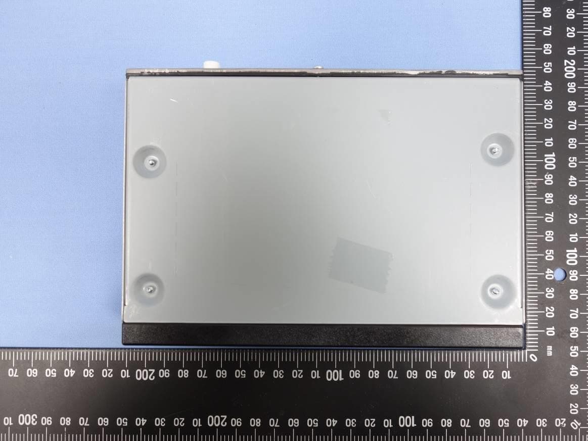
PQMCRM02
Dec 11, 2022RADIO BOX
Equipment Class
DSS - Part 15 Spread Spectrum Transmitter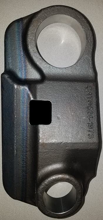
PQMTWS
May 21, 2020Caterpillar Trackwear Sensor
Equipment Class
DTS - Digital Transmission System
PQMMSS3I
Sep 15, 2015Caterpillar MSS3i RFID Key Reader Module
Equipment Class
DCD - Part 15 Low Power Transmitter Below 1705 kHz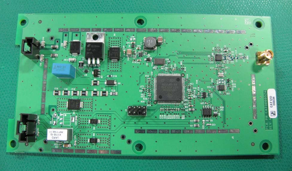
PQMASTOP1
Mar 27, 2012Wireless Onboard Transceiver
Equipment Class
DTS - Digital Transmission System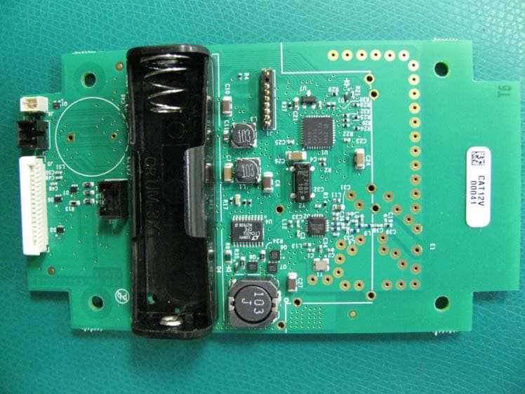
PQMASTOP2
Mar 27, 2012Wireless Handheld Transmitter
Equipment Class
DTS - Digital Transmission System