PQP-VR2RSPVideo Sender
Prime Electronics & Satellitics Inc.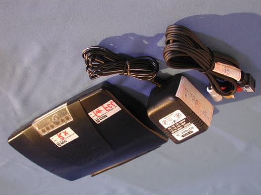
Click to zoom
Application Details
- Equipment Class
- DSC - Part 15 Security/Remote Control Transmitter
- Date of Grant
- Sep 11, 2001
- Application Purpose
- Original Equipment
- Date of Application
- Sep 11, 2001
- Equipment Note
- Video Sender
- Frequency Range
- 432.50000000 - 433.50000000
- Country
- Taiwan
Documents & Files
Document Text
Text extracted from the exhibit documents filed with the FCC. Open a document above to read the original.
Users Manual
Video Sender Operation Manual Table of Contents 1 Introduction............................................................................................................1 1.1 Features ..................................................................................................1 2 List of package contents.........................................................................................2 3 Outline....................................................................................................................3 4 Setting up units ......................................................................................................6 4.1 Transmitter : ...........................................................................................7 4.2 Receiver : ...............................................................................................8 5 Channel and dwell time selection ..........................................................................9 5.1 Transmitter channel setting ....................................................................9 5.2 Receiver setting......................................................................................9 6 Using the remote relay feature ............................................................................. 11 7 Trouble shooting ..................................................................................................12 IMPORTANT This equipment has been tested and found to comply with the limits for a Consumer Equipment RF Lighting device,pursuant to Part ISC of the FCC Rules. These limits are designed to provide reasonable protection against harmful interference in a residential installation. This equipment generates, uses and can radiate radio frequency energy and,if not installed and used in accordance with the instructions, may cause harmful interference to radio communications. However,there is no guarantee that interference will not occur in a particular installation.If this equipment does cause harmful interference to radio or television reception,which can be determined by turning the equipment off and on, the user is encouraged to try to correct the interference by one or more of the following measures: --Reorient or relocate the receiving antenna. --Increase the separation between the equipment and receiver. --Connect the equipment into an outlet on a circuir different from that to which the receiver is connected --Consult the dealer or an experienced radio/TV technician for help. CAUTION: Any changes or modifications not expressly approved by the grantee of this device could void the user’s authority to operate the equipment. Safety Pre-caution z To prevent fire or shock hazard, z Do not expose this product to rain or moisture. z Do not use near a bath tub, wash bowl, sink or laundry tub z Do not use in a wet basement or in or around a swimming pool. z Do not open the case of this product z Use only the power supply packed with it 1 Video Sender Manual Version 5/2 1 Introduction The new 2.4GHz system VF2RSP sends consistent, sharp audio and video images up to 100M to other rooms without running cable. The 2.4 GHz FM signal penetrates wall and avoids interference from other crowded 900 MHz band. Due to FM modulation, it provides a superior quality. With four channels, you could find optimal reception and transmit different sources using multiple pairs. The special hidden omni directional antenna maximizes the signal range. FCC,CE approved Easy installation. 1.1 Features z 2.4GHz signal avoids interference from the crowed 900MHz band z Provides clear reception up to 300 feet. z Four selectable PLL channels eliminate interference and allow use of multiple systems in the same area z Send stereo audio and clear video signals from Cable TV, VCR, LD, VCD, CD, satellite receiver to your TV in another room without running cable. z Penetrates walls, doors and ceilings. z Hidden 2.4GHz antenna design z Simple to use - just plug it in and switch it on. z infrared extender build-in 2 Video Sender Manual Version 5/2 2 List of package contents The following devices should be included in the box. One Transmitter TX One Receiver RX Two power adaptor One infrared extender Two A/V cable (or euro/scart cable) 3 Video Sender Manual Version 5/2 3 Outline Model# VF2RSP 4 Video Sender Manual Version 5/2 Transmitter (VT2RSP) Front REAR IR extender antenna Receives 433 remote control signals Power LED Power On/Off Switch Audio Right in Audio Left in VideoIn Channel selection DC12V out DC12V in IR Mouse in 5 Video Sender Manual Version 5/2 Receiver (VR2RSP) Front REAR IR extender antenna Send 433 remote control signals Power LED Video out Audio Left out Audio Right out Power On/Off Switch Channel selection Receives infrared signal from remoter controller DC12V in 6 Video Sender Manual Version 5/2 Setting up units It takes only few minutes to set up Video Sender. You could connect most of audio/video source to transmitter and connect TV to receiver in another location. There is no wire needed between transmitter and receiver. VCR VCD DVD TV Satellite Receiver Transmitter (VT2RSP) Receiver (VR2RSP) Camcorder 7 Video Sender Manual Version 5/2 3.1 Transmitter : z Make sure the ON/OFF switch is at the OFF position before setup. z Connect power adaptor to transmitter. z Plug power adaptor to wall outlet.. z Connect transmitter to A/V source you want to view or hear at another location. z Set the transmitting channel at back panel of transmitter. See “Channel and dwell time selection” to setup the channel.. z If you want to us remote relay function, please refer “Using the remote relay feature”. z Turn the ON/OFF switch to ON position, the related channel indicator should be lit. Example: From VCR with TV (must be purchased) TV RF IN Coaxial cable A/V 1 IN LINE A/V Cable OUT2 RF IN RF OUT LINE OUT1 LINE IN VCR Recommended TV connection for dual-output VCR Cable TV Hookup Signal from antenna To wall outlet CHANNEL 1 2 3 4 A/…
Text truncated - open the document above for the full version.
Cover Letter(s)
C:\windows\TEMP\probonholdemail.doc TIMCO TIMCOTIMCO TIMCO ENGINEERING INC. 849 NW State Road 45 Newberry, Florida 32669 http://www.timcoengr.com 888.472.2424 F 352.472.2030 email: tei@t imcoengr.com 4 Sept. 2001 FCC SUBJECT: PRIME ELECTRONICS & SATELLITICS INC. FCC ID: PQP-VR2RSP To Whom It May Concern: This is a composite device, the 433MHz transmitter is in the housing with the video transmitter, FCC ID: PQP-VT 2RSP. All through the test report it refers to the “video sender”, but this report is only for the control transmitter. This EUT is only for control and does not transmit either audio or video. 433MHz transmitter receives the control signals from the IR detector. The EUT is used to control the Video Receiver. This EUT receives the infrared signal and this control signal is used to modulate the 433MHz transmitter which in turns controls the Video Receiver. This is a combination device made up of the 2.4GHz video receiver and the 433MHz control transmitter. Sincerely, Sid Sanders
External Photos
Report No.: 014H008-1FI Page : 1 of 9 Version : 1.0 Attachment 2 : EUT Detailed Photographs (1) EUT Photo (2) EUT Photo
ID Label/Location Info
FCC ID.: PQP-VR2RSP 69, Tung-Yuan Rd., Chung-Li Industrial Park, Chung-Li City, Taoyuan, Taiwan. Tel: 886 3 461-5000 Fax: 886 3 461-4000 Video Sender Model No.: VR2RSP, VS1000, VS2000, VS3000 F F C C C C I I D D : : P P Q Q P P - - V V R R 2 2 R R S S P P This device complies with Part 15 of the FCC Rules. Operation is subject to the following two conditions: (1) this device may not cause harmful interference and (2) this device must accept any interference received, including interference that may cause undesired operation. S/N: Made in Taiwan
ID Label/Location Info
FCC ID.:PQP-VR2RSP 69, Tung-Yuan Rd., Chung-Li Industrial Park, Chung-Li City, Taoyuan, Taiwan. Tel: 886 3 461-5000 Fax: 886 3 461-4000 FCC ID The FCC ID Label will be placed on the equipment as shown in the photograph below. Lable here
Internal Photos
Report No.: 014H008-1FI Page : 2 of 9 Version : 1.0 (3) EUT Photo (4) EUT Photo Report No.: 014H008-1FI Page : 3 of 9 Version : 1.0 (5) EUT Photo (6) EUT Photo Report No.: 014H008-1FI Page : 4 of 9 Version : 1.0 (7) EUT Photo (8) EUT Photo Report No.: 014H008-1FI Page : 5 of 9 Version : 1.0 (9) EUT Photo Report No.: 014H008-1FI Page : 6 of 9 Version : 1.0 (10) EUT Photo Report No.: 014H008-1FI Page : 7 of 9 Version : 1.0 (11) EUT Photo (12) EUT Photo Report No.: 014H008-1FI Page : 8 of 9 Version : 1.0 Adapter: (13) EUT Photo (14) EUT Photo Report No.: 014H008-1FI Page : 9 of 9 Version : 1.0 (15) EUT Photo (16) EUT Photo
Operational Description
Operation Description The EUT is a 433.92MHz transmitter. The infrared remote control signal can be transferred to 433.92MHz radio frequency in ASK modulation. The transmission antenna is soldered on the PCB directly. The super generations type receiver was used. An external excitation was used when the test of receiver was performed.
Test Report
Report No. 014H008-1FI Page : 1 of 23 Version:1.0 Test Report Product Name : Video Sender Model No. : VR2RSP, VS1000, VS2000, VS3000 FCC ID.: PQP-VR2RSP Applicant : PRIME ELECTRONICS & SATELLITICS INC. Address : 69, Tung-Yuan Rd., Chung-Li Industrial Park, Chung-Li City, Taoyuan, Taiwan. Date of Receipt : March 30, 2001 Date of Test : June 26, 2001 Report No. : 014H008-1FI The Test Results relate only to the samples tested. The test report shall not be reproduced except in full without the written approval of QuieTek Corporation. This report must not be used to claim product endorsement by NVLAP any agency of the U.S. Government Report No. 014H008-1FI Page : 3 of 23 Version:1.0 TABLE OF CONTENTS Description Page 1. GENERAL INFORMATION.....................................................................................................4 1.1. EUT Description..........................................................................................................................4 1.2. Operation Description..................................................................................................................4 1.3. Tested System Details..................................................................................................................5 1.4. Configuration of tested System.....................................................................................................5 1.5. EUT Exercise Software................................................................................................................5 1.6. Test Facility................................................................................................................................6 2. Conducted Emission..................................................................................................................7 2.1. Test Equipment List.....................................................................................................................7 2.2. Test Setup...................................................................................................................................7 2.3. Limits.........................................................................................................................................7 2.4. Test Procedure.............................................................................................................................8 2.5. Test Result of Conducted Emission...............................................................................................9 3. Radiated Emission...................................................................................................................10 3.1. Test Equipment..........................................................................................................................10 3.2. Test Setup.................................................................................................................................10 3.3. Limits........................................................................................................................................11 3.4. Test Procedure...........................................................................................................................12 3.5. Test Result of Radiated Emission................................................................................................13 4. Occupied Bandwidth of Raidated Emission.............................................................................15 4.1. Test Equipment..........................................................................................................................15 4.2. Test Setup.................................................................................................................................15 4.3. Test Condition...........................................................................................................................15 4.4. Limits.......................................................................................................................................15 4.5. Test Procedure...........................................................................................................................15 4.6. Test Result of Occupied Bandwidth of Raidated Emission............................................................16 5. Duty Cycle Measurement.........................................................................................................17 5.1. Test Equipment..........................................................................................................................17 5.2. Test Setup.................................................................................................................................17 5.3. Test Condition...........................................................................................................................17 5.4. Test Proceudre...........................................................................................................................17 5.5. Test Result of Duty Cycle Measurement......................................................................................18 6. EMI Reduction Method During Compliance Testing...............................................................19 7. Attachment..............................................................................................................................20 Attachment 1: EUT Test Photographs Attachment 2: EUT Detailed Photographs Report No. 014H008-1FI Page : 4 of 23 Version:1.0 1. GENERAL INFORMATION 1.1. EUT Description Product Name : Video Sender Trade Name : PRIME, PBI FCC ID. : PQP-VR2RSP Model No. : VR2RSP, VS1000, VS2000, VS3000 Working Frequency : 433.92MHz Channel Number : 1 Type of Modulation : ASK Operator Selection of Operating Frequency : Manual Switch Power Adapter : AHEAD Cable Out: Non-Shielded, 1.8m Note: 1. This device is a 433.9MHz V…
Text truncated - open the document above for the full version.
Test Setup Photos
Report No.: 014H008-1FI Page: 1 of 3 Version: 1.0 Attachment 1 : EUT Test Photographs Front View of Conducted Test Back View of Conducted Test Report No.: 014H008-1FI Page: 2 of 3 Version: 1.0 Front View of Radiated Test Back View of Radiated Test Report No.: 014H008-1FI Page: 3 of 3 Version: 1.0 Front View of Radiated Test (High Frequency) Back View of Radiated Test (High Frequency)
Contact Information
Applicant
willian Chiang Hsieh(R&D Engineer)
Test Firm
DEKRA Testing and Certification Co., Ltd.Sky Hsu
Technical Specifications
| # | Rule Parts | Frequency Range | Power Output |
|---|---|---|---|
| 1 | 15.231 | 432.5 MHz - 433.5 MHz | - |
Other Applications from Prime Electronics & Satellitics Inc.

PQP-SPLDT1
Aug 05, 2012Wireless HD Transmitter
Equipment Class
DXX - Part 15 Low Power Communication Device Transmitter
PQP-SPLDR1
Aug 05, 2012Wireless HD Receiver
Equipment Class
DXX - Part 15 Low Power Communication Device Transmitter
PQP-WI233L
Nov 09, 2005Wireless LAN PCI Adapter
Equipment Class
DTS - Digital Transmission System
PQP-WU233P
Mar 30, 2005Wireless LAN USB Adapter
Equipment Class
DTS - Digital Transmission System
PQP-WI233G
Dec 18, 2004Wireless LAN PCI Adapter
Equipment Class
DTS - Digital Transmission System