PQPWA222PWireless LAN AP
Prime Electronics & Satellitics Inc.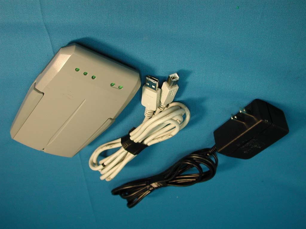
Click to zoom
Application Details
- Equipment Class
- DSS - Part 15 Spread Spectrum Transmitter
- Date of Grant
- Aug 14, 2002
- Application Purpose
- Original Equipment
- Date of Application
- Aug 14, 2002
- Equipment Note
- Wireless LAN AP
- Frequency Range
- 2400.00000000 - 2483.50000000
- Country
- Taiwan
Documents & Files
Document Text
Text extracted from the exhibit documents filed with the FCC. Open a document above to read the original.
Users Manual
Wireless Access Point User Manual Ver. 1.0 Table of Contents 1. INTRODUCTION 1 2. ADAPTER INSTALLATION 2 HARDWARE/OS REQUIREMENTS 2 INSTALLING THE HARDWARE 3 INSTALLING THE DRIVER 3 INSTALLING THE SOFTWARE 4 3. BRIDGE ACCESS POINT INSTALLATION 5 HARDWARE/OS REQUIREMENTS 5 INSTALLING THE HARDWARE 5 INSTALLING THE BRIDGE MANAGER 6 4. DEVICE & NETWORK MANAGEMENT 8 DEVICE MANAGER 9 NETWORK MANAGEMENT 11 ADDING NODES TO THE NETWORK 11 BRIDGE DEVICE MANAGER 12 SETTING UP PROFILES 12 SETTING UP IP/SNMP SETTINGS 13 SWITCHES AND CONNECTORS 14 5. UNINSTALL HARDWARE & SOFTWARE 15 11 Introduction This chapter is your starting point for the rest of this manual. his guide describes how to install and operate the Wireless LAN PCMCIA Adapter and Access Point evaluation kits. If you are installing PCMCIA Adapter start the installation by turning to Adapter Installation on page 2. If you are installing a Access Point, start the installation by turning to Access Point Installation on page 5. For instructions on how to use the software, turn to page 8. The majority of the screenshots printed in this manual are taken from Windows XP, the screens on your computer may look slightly different. Chapter 1 T Adapter Installation This chapter will walk you through the hardware, driver and software installation of the wireless adapter. Hardware/OS Requirements ß Pentium II PC ß 64 Megs RAM ß Windows 98/ME/2000/XP NOTE: Before installing, please remove any prior versions using the instructions on page 15. Chapter 2 33 Installing the Hardware For PCMCIA Insert the PCMCIA card in the computer and power on the computer. (Note that the computer may be on or off when the PCMCIA card is inserted). For PCI Install the PCI card in the computer. Attach the supplied antenna to the card BEFORE powering up the PC. Be sure to match the lead marked RED with the antenna connector that is marked RED and power on the computer. For MiniPCI Install the MiniPCI card in your hardware application. Attach the supplied antenna to the card BEFORE powering up the PC. Be sure to match the lead marked RED with the antenna connector that is marked RED and power on the computer. Should you not have a device with a MiniPCI slot available, a MiniPCI to PCI converter card can be used to install the MiniPCI card in a PCI slot. A converter card can be purchased from: Installing the Driver After installing the adapter as described on page 3, Windows will notify you with a ‘New Hardware Found’ dialog box. Following this, the Windows installation wizard will detect the adapter. ß Insert the installation CD into your CDROM drive and click ‘Next’. ß Windows 98 - Select ‘Search for the best driver for your device’, and click ‘Next’. Specify to search the CD Rom drives (check the box) and click ‘Next’. ß Windows ME/2000/XP - Select the “Automatic Search” option and click ‘Next’. 44 ß Windows will find the drivers located on the CD and begin to install them. This may take up several minutes. ß When completed click ‘Finish’. You will next be asked to reboot the computer. Click ‘Yes’. Note: If the system does not shut down (or restart) within 2 minutes, manually power down the computer and then power it back up. This completes the driver installation; please continue with the software installation in the next paragraph. Installing the Software This paragraph describes the installation of the Network & Device management software. After completing the hardware and driver installation as described in the previous paragraphs, the software installation will automatically start. Follow the instructions on the screen to install the software. You will be asked some basic questions including: ß Agreement to the (blank) license agreement ß Your name and company name ß SSID (This will be the SSID or network name immediately after installation, note that you can always change this after the installation) ß In some cases, the installation program may prompt you to install JRE (Java Runtime Environment) which is necessary to run the software. Click “Yes” and follow the instructions. After the software is installed you’ll be asked to reboot once more after which the installation is complete. You can now use the product as desired. Refer to the remainder of this manual for operating instructions. Note: If this is the first time a network device has been installed, after re-starting the system, you may need to enter a Windows network ‘User name’ and ‘Password’. See Windows help for more information. 55 Bridge Access Point Installation This chapter will walk you through the hardware and Bridge Device Manager installation of the Bridge Access Point. Hardware/OS Requirements ß Pentium II PC ß 64 Megs RAM ß Windows 98/ME/2000/XP Installing the Hardware Perform the following steps to install the wireless Access Point (AP). ß If applicable, insert the Ethernet cable into the RJ45 connector (labeled “TO HUB”) on the AP to connect to a hub, router, cable or DSL modem. If you have received a AP with two Ethernet ports, the other port can be used to connect a wired client node to the network. Next, apply power to the AP by plugging in the power adapter supplied with the evaluation kit. This completes the hardware portion of the installation. The next step is to add the AP into the wireless network. There are three options configuration of the bridge: ß “Enroll” the bridge in the network (Multimedia Mode only). Turn “Adding nodes to the network” on page 11 to continue the installation by using the Chapter 3 Network Management application on a wireless active PC node to enroll the bridge into the network. ß The BAP provides an SNMPv1 agent and provides support for the standard IEEE 802.11 MIB and proprietary extensions (MIB files are included on the evaluation CD). These objects can be read and configured via a standard SNMP MIB Browser. ß Alternatively, read the below “Installing the Bridge Manager” section to manually configure the Bridge Access Installing the Bridge Manager The Access P…
Text truncated - open the document above for the full version.
Block Diagram
FREQ. Synthesizer TX/RX ETHERNET/USB Bodega CS22250/CRESTA 3R wireless ACESS POINT REFERENCE DESIGN 48MHz CLK POWER SUPPLY CONDITIONING 3.3V 2.8V 1.8V CS22250 MAC BOOTROM MEMORY SI4126BM RF3000 RF2948B I/Q TXI/Q RX BasebandProcessor RF/IF Processor PA LNA Cresta 3R ANT 1/2 Switching (PLD) Control logic 44MHz CLK OSC.
External Photos
Report No.: 027H046FI Page : 1 of 6 Version:1.0 Attachment 2 : EUT Detailed Photographs (1) EUT Photo (2) EUT Photo
ID Label/Location Info
FCC ID.: PQPWA222P FCC ID AND DoC Label The FCC ID and DoC Label will be placed on the equipment as shown in the photograph below. Wireless LAN Card PESI Model No.: WA222P TESTED TO COMPLY WITH FCC STANDARDS FOR HOME OR OFFICE USE S/N: Made in Taiwan Wireless LAN Card Model No.: WA222P F F C C C C I I D D : : P P Q Q P P W W A A 2 2 2 2 2 2 P P This device complies with Part 15 of the FCC Rules. Operation is subject to the following two conditions: (1) this device may not cause harmful interference and (2) this device must accept any interference received, including interference that may cause undesired operation. S/N: Made in Taiwan
ID Label/Location Info
FCC ID.: PQPWA222P FCC ID AND DoC Label The FCC ID and DoC Label will be placed on the equipment as shown in the photograph below. Wireless LAN Card PESI Model No.: WA222P TESTED TO COMPLY WITH FCC STANDARDS FOR HOME OR OFFICE USE S/N: Made in Taiwan Wireless LAN Card Model No.: WA222P F F C C C C I I D D : : P P Q Q P P W W A A 2 2 2 2 2 2 P P This device complies with Part 15 of the FCC Rules. Operation is subject to the following two conditions: (1) this device may not cause harmful interference and (2) this device must accept any interference received, including interference that may cause undesired operation. S/N: Made in Taiwan
Internal Photos
Report No.: 027H046FI Page : 2 of 6 Version:1.0 (3) EUT Photo (4) EUT Photo Report No.: 027H046FI Page : 3 of 6 Version:1.0 (5) EUT Photo (6) EUT Photo Report No.: 027H046FI Page : 4 of 6 Version:1.0 (7) EUT Photo (8) EUT Photo Report No.: 027H046FI Page : 5 of 6 Version:1.0 (9) EUT Photo (10) EUT Photo Report No.: 027H046FI Page : 6 of 6 Version:1.0 (11) EUT Photo (12) EUT Photo
Operational Description
1.1. Operational Description EUT is an USB interface 2.4GHz wireless LAN AP with 11 channels. This device provided one kind of transmitting speed 11Mbps. The device of RF carrier is CCK. The device adapts direct sequence spread spectrum modulation. The dual monopole antenna soldered on PCB provides diversity function to improve the receiving function. Data can be transmitted by the radio signal connect to the Internet or Local network.
Test Report
Report No. 027H046FI Page : 1 of 44 Version:1.0 Test Report Product Name : Wireless Access Point Model No. : WA222P FCC ID.: PQPWA222P Applicant : PRIME ELECTRONICS & SATELLITICS INC. Address : 69, Tung-Yuan Rd., Chung-Li Industrial Park, Chung-Li City, Taoyuan, Taiwan. Date of Receipt : July. 12, 2002 Date of Test : July. 22, 2002 Report No. : 027H046FI The Test Results relate only to the samples tested. The test report shall not be reproduced except in full without the written approval of QuieTek Corporation. This report must not be used to claim product endorsement by NVLAP any agency of the U.S. Government Report No. 027H046FI Page : 3 of 44 Version:1.0 TABLE OF CONTENTS Description Page 1. GENERAL INFORMATION .....................................................................................................5 1.1. EUT Description............................................................................................................................5 1.2. Operational Description ................................................................................................................5 1.3. Tested System Details....................................................................................................................6 1.4. Configuration of tested System .....................................................................................................7 1.5. EUT Exercise Software .................................................................................................................7 1.6. Test Facility ...................................................................................................................................8 2. Conducted Emission....................................................................................................................9 2.1. Test Equipment..............................................................................................................................9 2.2. Test Setup ......................................................................................................................................9 2.3. Limits ............................................................................................................................................9 2.4. Test Procedure .............................................................................................................................10 2.5. Test Result of Conducted Emission.............................................................................................11 3. Peak Power Output ...................................................................................................................12 3.1. Test Equipment............................................................................................................................12 3.2. Test Setup ....................................................................................................................................12 3.3. Test Condition .............................................................................................................................12 3.4. Limit ............................................................................................................................................12 3.5. Test Result of Peak Power Output...............................................................................................13 4. RF Exposure Evaluation ...........................................................................................................14 4.1. Friis Formula ...............................................................................................................................14 4.2. EUT Operation condition ............................................................................................................14 4.3. Test Result of RF Exposure Evaluation.......................................................................................15 5. Radiated Emission .....................................................................................................................16 5.1. Test Equipment............................................................................................................................16 5.2. Test Setup ....................................................................................................................................16 5.3. Limits ..........................................................................................................................................17 5.4. Test Procedure .............................................................................................................................17 5.5. Test Result of Radiated Emission................................................................................................18 6. Band Edge ..................................................................................................................................27 6.1. Test Equipment............................................................................................................................27 6.2. Test Setup ....................................................................................................................................27 6.3. Test Condition .............................................................................................................................28 6.4. Limit ............................................................................................................................................28 6.5. Test Procedure .............................................................................................................................28 6.6. Test Result of Band Edge ............................................................................................................29 7. Occupied Bandwidth ........................................................................…
Text truncated - open the document above for the full version.
Test Setup Photos
Report No.: 027H046FI Page : 1 of 3 Version:1.0 Attachment 1: EUT Test Setup Photographs Front View of Conducted Test Back View of Conducted Test Report No.: 027H046FI Page : 2 of 3 Version:1.0 Front View of Radiated Test Back View of Radiated Test Report No.: 027H046FI Page : 3 of 3 Version:1.0 Front View of Radiated Test (Horn)
Contact Information
Applicant
willian Chiang Hsieh(R&D Engineer)
Test Firm
DEKRA Testing and Certification Co., Ltd.Sky Hsu
Technical Specifications
| # | Rule Parts | Frequency Range | Power Output |
|---|---|---|---|
| 1 | 15C,15C | 2.40 GHz - 2.48 GHz | 46.00 mW |
Other Applications from Prime Electronics & Satellitics Inc.

PQP-SPLDT1
Aug 05, 2012Wireless HD Transmitter
Equipment Class
DXX - Part 15 Low Power Communication Device Transmitter
PQP-SPLDR1
Aug 05, 2012Wireless HD Receiver
Equipment Class
DXX - Part 15 Low Power Communication Device Transmitter
PQP-WI233L
Nov 09, 2005Wireless LAN PCI Adapter
Equipment Class
DTS - Digital Transmission System
PQP-WU233P
Mar 30, 2005Wireless LAN USB Adapter
Equipment Class
DTS - Digital Transmission System
PQP-WI233G
Dec 18, 2004Wireless LAN PCI Adapter
Equipment Class
DTS - Digital Transmission System