PQY-4710874200036RF Wireless Keyboard
Cellink Co., Ltd.
Click to zoom
Application Details
- Equipment Class
- DXX - Part 15 Low Power Communication Device Transmitter
- Date of Grant
- Nov 08, 2001
- Application Purpose
- Original Equipment
- Date of Application
- Nov 08, 2001
- Equipment Note
- RF Wireless Keyboard
- Frequency Range
- 26.96000000 - 27.28000000
- Company
- Cellink Co., Ltd.
- Country
- Taiwan
Documents & Files
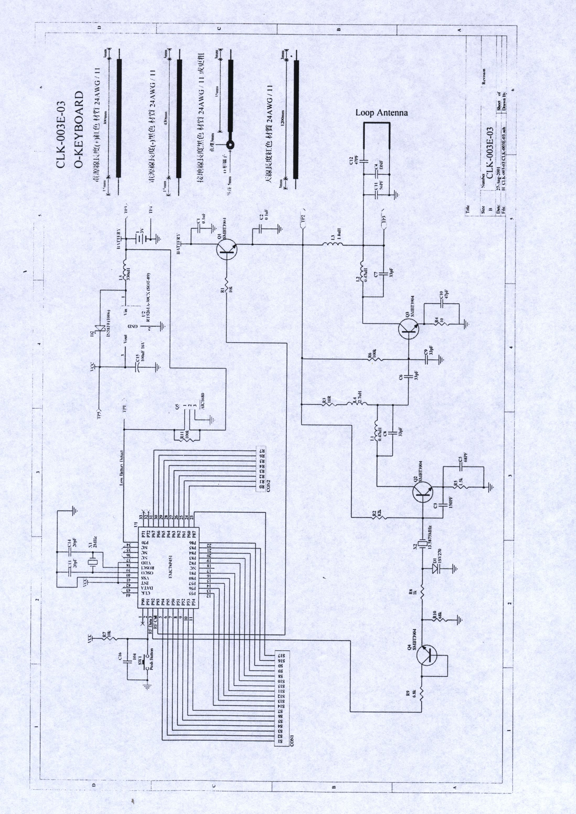
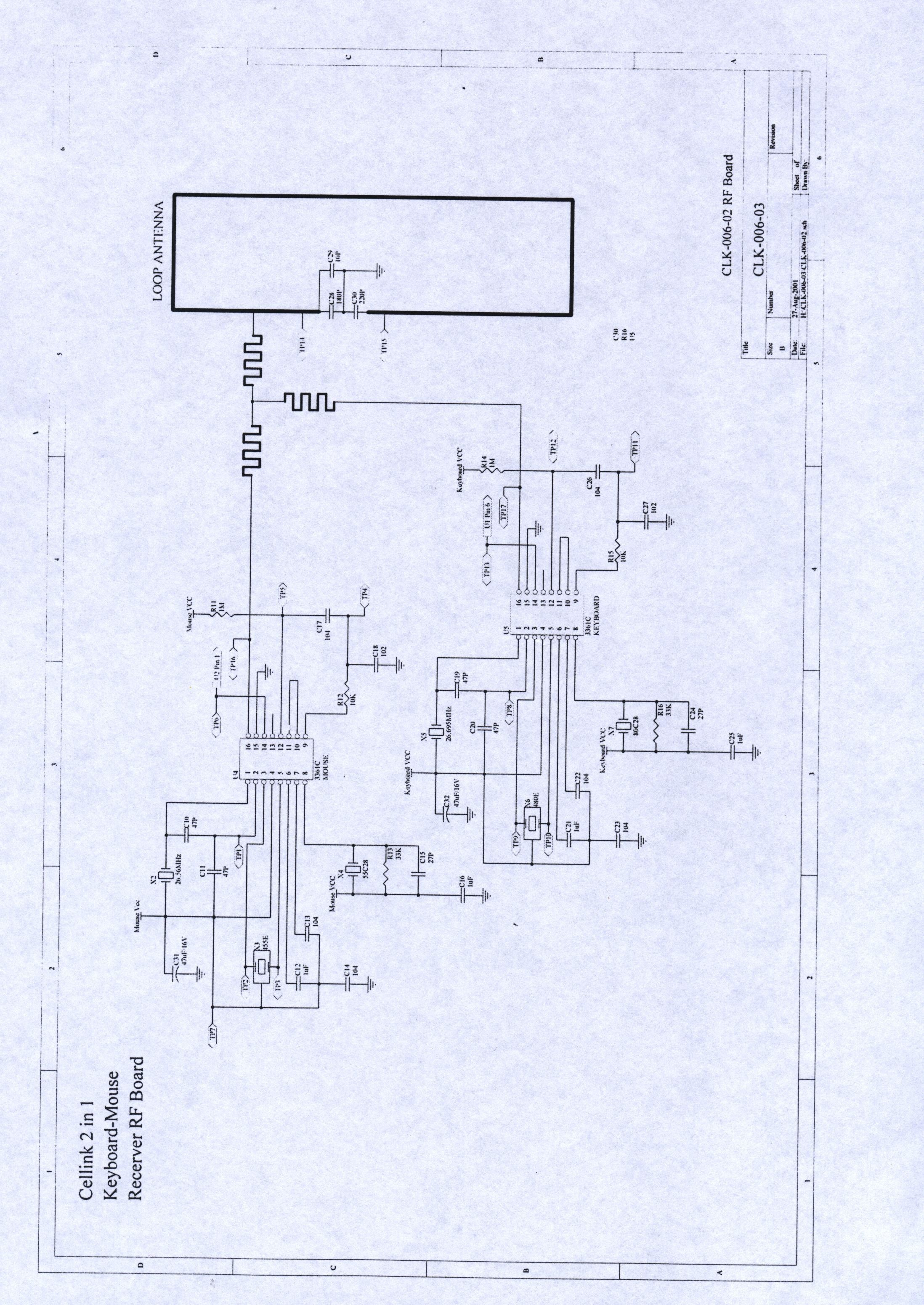
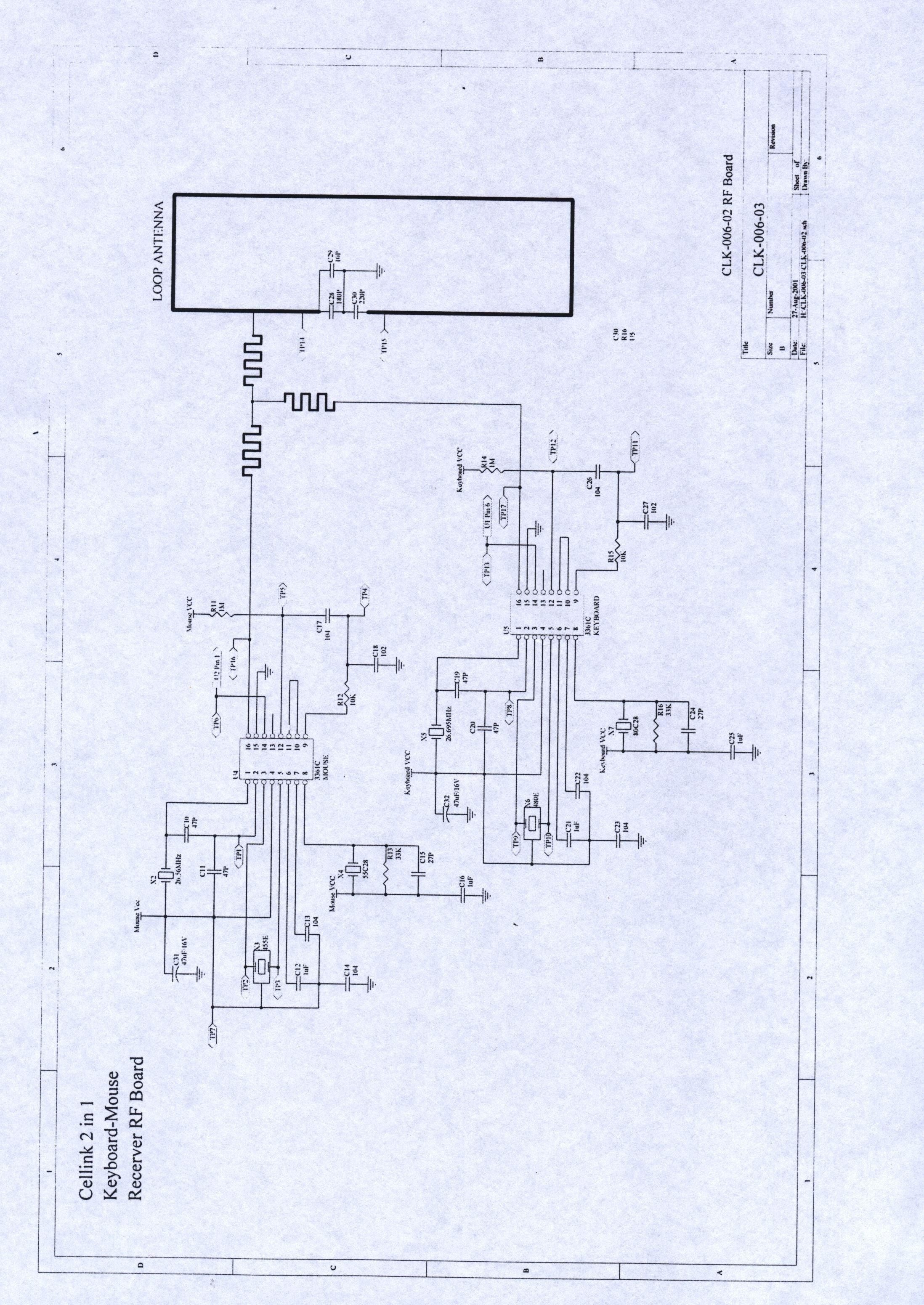
Document Text
Text extracted from the exhibit documents filed with the FCC. Open a document above to read the original.
Users Manual
RF COMBO 1 BATTERY INSTALLATION Mouse 1. As shown as fig.1 to fig.4, please hold the mouse and press the center part of the two keys with one thumb. Meanwhile, with the other hand, pull the top cap backward and open it. 2. Put two AAA alkaline batteries according to its direction. Then, put back the top cap (as shown as fig.3) aiming at and along with the waist of the mouse. Caution: When battery power is low, the mouse pattern will show red color on the right-down corner of window screen for warning. Keyboard Open the battery cap, which is on keyboard's reverse side, place 4 pieces AAA Alkaline batteries, and put the cap back. Every time after having changed batteries, please reset up the mouse according to the steps of " SETUP FOR USE". HARDWARE INSTALLATION 1. Shut down the power of the computer. (Caution: Do not plug in or out USB or PS/2 connector port when the power of the computer is still on, otherwise will damage the computer.) 2. Connect the green connector of the receiver (according to the type you have bought) to the PS/2 connection port of the computer, or connect the white connector to the USB connection port on the computer. 3. Turn on the computer. SOFTWARE INSTALLATION (DRIVE PROGRAM) 1. Insert the CD / Driver into Drive-D (In case the CD-ROM is in D-drive). 2. Get into "execution" on window screen. Click twice on the file of "setup exe" in D-drive of the CD to proceed setup, and follow the steps indicated in the screen to complete the setup. 3. After the setup has been completed, the screen will restart automatically. And, it will show a mouse pattern on the right-down corner of the screen. Caution: When it is in PS/2 mode, this driver doesn't support "Low battery display". SETUP FOR USE 1. MOUSE: Aim the front point of the mouse at receiver. PRESS FIRST THE BUTTON ON THE REVERSE SIDE OF MOUSE, THEN PRESS THE CONNECTOR BUTTON ON THE RECEIVER. (NEVER DO THE CONTRARY WAY.) The LED lights of the mouse and keyboard will light up. When mouse LED light goes off , it means the setup of the mouse is completed. 2. KEYBOARD: PRESS THE BUTTON ON THE REVERSE SIDE OF KEYBOARD. When the LED light of keyboard goes off, it means the setup of the keyboard is completed as well. And you may start to work with this RF Combo device. 3. The setup must be completed in one minute. If exceeded, please repeat the steps. MOUSE BUTTON FUNCTION SETUP 1. Get into setup from the control desk or directly click into the mouse pattern shown in right-down corner of the screen. It shows the functions as following: . Button : setup for habit of using right or left hand, adjustment of the speed of continuously pressing twice the mouse buttons, adjustment of numbers of column for each rolling. . Mouse Marking: to set up the pattern or mouse marking. . Wheel : to set up the functions of hot key, zooming, and rolling of auto-turning. . Motion : to set up the moving speed of mouse sign, the length of the dragging tail, and non-border, etc. 2. After the function is set up, press "Yes" to store the new setup. TROUBLESHOOTING If the mouse or keyboard doesn’t function well, please follow the steps below: 1. Check if the connector of USB or PS/2 port is well connected or not. 2. Check if the positive(+) and negative(-) pole of the battery is put correctly. If the power is low, the mouse will become sluggish or slow. 3. Reset: Follow the steps of "Setup for use". HARDWARE MAINTENANCE AND CLEANING When the mouse doesn't move smoothly or its speed is not normal, please clean the rolling ball of the mouse. The steps are as follows: 1. Follow the arrow direction (open with clockwise direction, and close with counterclockwise direction) to turn the rolling ball cap, which is under the mouse, to take out the ball. 2. Wipe the ball with a clean cloth dampen with clean water or alcohol, and wipe the dust inside the mouse with a dry clean cloth. After the cleaning is done, put back the ball and the cap. (Caution: never clean with organic dissolvent.) ENVIRONMENT To avoid environmental interference, which will reduce the effective distance, it should be noted below for the mouse and receiver: 1. Do not put the mouse and receiver on metal cabinet or metal desk. It's better not having metal or interference source around, which may affect the RF communication, and reduce the communication distance. 2. The ideal for the mouse and receiver is having 15-20 cm distant from computers or, in any open place. 3. Keep a distance of more than 1.5m to avoid interference if there are other RF devices in using HOW TO REMOVE THE DRIVER - From the windows taskbar, click the Start, then select Setup, Control desk, Add / Remove program. Find the file USB RF MOUSE and click Add / Remove. - In the window Confirm File Deletion, click YES. - In the window RF MOUSE , click the OK. - Check if the driver is already removed. If yes, click OK. For any problem in using this device, please reach to the Customer Service Center through the e-mail on the website. A response will be forwarded by e-mail to you very soon
External Photos
PHOTOS OF TESTING A. EUT front side view (Transmitter) B. EUT back side view PHOTOS OF TESTING C. EUT top side view (Receiver) D. EUT bottom side view
ID Label/Location Info
FCC LABLE Sample of FCC ID Label FCC ID : PQY-4710874200036 TRADE NAME : CELLINK CO., LTD. MODEL NO. : RF Combo 1 THIS DEVICE COMPLIES WITH PART 15 OF THE FCC RULES. OPERATION IS SUBJECT TO THE FOLLOWING TWO CONDITIONS. (1) THIS DEVICE MAY NOT CAUSE HARMFUL INTERFERENCE AND (2) THIS DEVICE MUST ACCEPT ANY INTERFERENCE RECEIVED, INCLUDING INTERFERENE THAT CAUSE UNDESIRED OPERATION.
Internal Photos
PHOTOS OF TESTING A. EUT inside whole view (Transmitter) B. EUT case inside whole view PHOTOS OF TESTING C. EUT inside whole view (Receiver) D. EUT case inside whole view PHOTOS OF TESTING E. Main board component side (Transmitter) F. Main board solder side PHOTOS OF TESTING G. Main board component side (Receiver) H. Main board solder side
Test Report
Class B Certification Application Under Part 15, Subpart C EUT RF Wireless Keyboard MODELRF Combo 1 FCC ID PQY-4710874200036 SRT REPORT # FID1H018 PREPARED FOR CELLINK CO., LTD. 11F, NO. 102, SEC. 1, HSIN TAI WU RD., HIS-CHIH, TAIPEI, TAIWAN, R.O.C. Spectrum Research & Testing Lab. FCC ID PQY-4710874200036 Report # FID1H018 PAGE 2 OF 29 Spectrum Research & Testing Lab. FCC ID PQY-4710874200036 Report # FID1H018 PAGE 3 OF 29 EMI TESTING REPORT EUT : RF Wireless Keyboard MODEL : RF Combo 1 FCC ID : PQY-4710874200036 PREPARED FOR CELLINK CO., LTD. 11F, NO. 102, SEC. 1, HSIN TAI WU RD., HIS-CHIH, TAIPEI, TAIWAN, R.O.C. PREPARED BY SPECTRUM RESEARCH & TESTING LABORATORY INC. NO. 101-10 , LING 8 , SHAN-TONG LI CHUNG – LI CITY , TAOYUAN, TAIWAN , R. O. C. TEL (03) 4987684 FAX (03) 4986528 Spectrum Research & Testing Lab. FCC ID PQY-4710874200036 Report # FID1H018 PAGE 4 OF 29 TABLE OF CONTENTS 1. TEST REPORT CERTIFIICATION................................................................ 5 2. TEST STATEMENT 2 . 1 TEST STATEMENT.............................................................................. 6 2 . 2 DEPARTURE FROM DOCUMENT POLICIES, PROCEDURE OR SPECIFICATIONS, TEST STATEMENT....................... 6 3. EUT MODIFICATIONS................................................................................. 7 4. CONDUCTED POWER LINE TEST 4 . 1 TEST EQUIPMENT.............................................................................. 8 4 . 2 TEST PROCEDURE.............................................................................. 8 4 . 3 TEST SETUP....................................................................................... 9 4 . 4 CONFIGURATION OF THE EUT......................................................... 10-11 4 . 5 EUT OPERATING CONDITION............................................................. 12 4 . 6 EMISSION LIMITS............................................................................... 12 4 . 7 CONDUCTED EMISSION TEST RESULTS............................................. 13 5. RADIATED EMISSION TEST 5 . 1 TEST EQUIPMENT.............................................................................. 14 5 . 2 TEST PROCEDURE............................................................................. 14 5 . 3 TEST SETUP...................................................................................... 15-16 5 . 4 CONFIGURATION OF THE EUT......................................................... 17 5 . 5 EUT OPERATING CONDITION............................................................. 17 5 . 6 EMISSION LIMITS............................................................................... 17 5 . 7 RADIATED EMISSION TEST RESULTS................................................ 18 5 . 8 FUNDAMENTAL FREQUENCY TEST..................................................... 19-24 6. BANDWIDTH 6 . 1 LIMIT.................................................................................................. 25 6 . 2 RESULTS.............................................................................................. 25 7. CHANGE THE VOLTAGE +/-15% TEST..................................................... 26 8. CHANGE THE TEMPERATURE TEST......................................................... 27-29 Spectrum Research & Testing Lab. FCC ID PQY-4710874200036 Report # FID1H018 PAGE 5 OF 29 1. TEST REPORT CERTIFICATION APPLICANT CELLINK CO., LTD. ADDRESS 11F, NO. 102, SEC. 1, HSIN TAI WU RD., HIS-CHIH, TAIPEI, TAIWAN, R.O.C. EUT DESCRIPTION RF Wireless Keyboard (A) POWER SUPPLY RECEIVER FROM PC TRANSMITTER FROM BATTERY (B) MODEL RF Combo 1 (C) FCC ID PQY-4710874200036 FINAL TEST DATE 08/31/2001 MEASUREMENT PROCEDURE USED * PART 15 SUBPART C OF FCC RULES AND REGULATIONS ( 47 CFR PART 15) * ANSI C63.4 - 1992 * TEST PROCEDURE AND DATA ARE TRACEABLE TO NATIONAL OR INTERNATIONAL STANDARDS. We hereby certify that The measurements contained in this report were made in accordance with the procedures indicated, and the energy emitted by the equipment was found to be within the limits applicable. TESTING ENGINEER DATE Ken Su SUPERVISOR DATE Sunyou Chen APPROVED BY DATE Johnson Ho Spectrum Research & Testing Lab. FCC ID PQY-4710874200036 Report # FID1H018 PAGE 6 OF 29 2. TEST STATEMENT 2 . 1 TEST STATEMENT 1. This letter is to explain the test condition of this project. The EUT be tested as the following status. 2. The data was shown in this report reflects the worst – case data for the condition as listed above. Please disregard any other processor (s) speed shown in this user manual. 3. EUT Conditions. Transmitting frequency : 27 .175MHz Operation range : 6 feet Hardware resolution : 600 dpi 4. NVLAP logo is to be approved by management (it is according to NVLAP requirement if it need) before use. 2 . 2 DEPARTURE FROM DOCUMENT POLICIES, PROCEDURE OR SPECIFICATIONS , THE STATEMNT 1. Did have Any departure from document policies & procedures or from specifications. Yes , No . If yes , the description as below. 2. .The certificate and report shall not be reproduced except in full , without the written approval of SRT laboratory. 3. .The report must not be used by the client to claim product endorsement by NVLAP or any agency the government. 4. This product is a test sample that was shown as the photos of this test report only. 5. The effect that the results relate only to the items tested. Spectrum Research & Testing Lab. FCC ID PQY-4710874200036 Report # FID1H018 PAGE 7 OF 29 3. EUT MODIFICATIONS No modification by SRT lab. Spectrum Research & Testing Lab. FCC ID PQY-4710874200036 Report # FID1H018 PAGE 8 OF 29 4. CONDUCTED POWER LINE TEST 4 . 1 TEST EQUIPMENT The following test equipment were used during the conducted power line test EQUIPMENT/ FACILITIES SPECIFICATIONS MANUFACTURER MODEL#/ SERIAL# DATE OF CAL. & CAL. CENTER DUE DATE FINAL TEST EMI TEST RECEIVER 9 KHz TO 30 MHz ROHDE & SCHWARZ ESHS30/ 826003/008 MARCH 2001 R & S 1Y EMI TEST RECEIVER 9 KHz TO 2750 MHz ROHDE & SCHWARZ ESCS…
Text truncated - open the document above for the full version.
Test Setup Photos
PHOTOS OF TESTING A. Conducted test front view B. Conducted test back view PHOTOS OF TESTING C. Open site test front view D. Open site test back view PHOTOS OF TESTING E. Fundermental frequency test view
Contact Information
Applicant
Ting-Ting Huang(Vice President)
Test Firm
Spectrum Research & Testing Lab.Linda Chiang
Technical Specifications
| # | Rule Parts | Frequency Range | Power Output |
|---|---|---|---|
| 1 | 15C | 26.96 MHz - 27.28 MHz | - |
Other Applications from Cellink Co., Ltd.

PQY-4710874204881
Jun 07, 2006IPod Shuffle FM Transmitter
Equipment Class
DXX - Part 15 Low Power Communication Device Transmitter
PQY-4710874204737
May 16, 2006Bluetooth Stereo Box
Equipment Class
DSS - Part 15 Spread Spectrum Transmitter
PQY-4710874204591
Jan 23, 2006Bluetooth USB Adapter
Equipment Class
DSS - Part 15 Spread Spectrum Transmitter
PQY-4710874204751
Dec 07, 2005Bluetooth USB Adapter
Equipment Class
DSS - Part 15 Spread Spectrum Transmitter
PQY-4710874204669
Nov 06, 2005MINI BLUETOOTH HEADSET
Equipment Class
DSS - Part 15 Spread Spectrum Transmitter