PRL-IWE1100Wireless Internet Access Server Appliance
Interepoch Technology, Inc.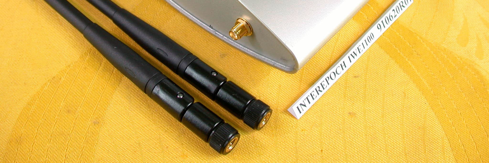
Click to zoom
Application Details
- Equipment Class
- DSS - Part 15 Spread Spectrum Transmitter
- Date of Grant
- Sep 24, 2002
- Application Purpose
- Original Equipment
- Date of Application
- Sep 24, 2002
- Equipment Note
- Wireless Internet Access Server Appliance
- Frequency Range
- 2412.00000000 - 2462.00000000
- Company
- Interepoch Technology, Inc.
- Country
- Taiwan
Documents & Files
Document Text
Text extracted from the exhibit documents filed with the FCC. Open a document above to read the original.
Users Manual
Wireless Internet Access Server Ap- pliance User’s Guide Version: 2.4 Last Updated: 09/026/2002 i Federal Communication Commission Interference Statement This equipment has been tested and found to comply with the limits for a Class B digital device, pur- suant to Part 15 of the FCC Rules. These limits are designed to provide reasonable protection against harmful interference in a residential installation. This equipment generates, uses and can radiated ra- dio frequency energy and, if not installed and used in accordance with the instructions, may cause harmful interference to radio communications. However, there is no guarantee that interference will not occur in a particular installation. If this equipment does cause harmful interference to radio or television reception, which can be determined by turning the equipment off and on, the user is en- couraged to try to correct the interference by one of the following measures: ! Reorient or relocate the receiving antenna. ! Increase the separation between the equipment and receiver. ! Connect the equipment into an outlet on a circuit different from that to which the receiver is connected. ! Consult the dealer or an experienced radio/TV technician for help. FCC Caution: To assure continued compliance, any changes or modifications not expressly approved by the party responsible for compliance could void the user’s authority to operate this equipment. This transmitter must not be co-located or operating in conjunction with any other antenna or trans- mitter. FCC Radiation Exposure Statement This equipment complies with FCC radiation exposure limits set forth for an uncontrolled environ- ment. This equipment should be installed and operated with minimum distance 20 cm between the radiator & your body. This device complies with Part 15 of the FCC Rules. Operation is subject to the following two condi- tions: (1) This device may not cause harmful interference, and (2) this device must accept any inter- ference received, including interference that may cause undesired operation. R&TTE Compliance Statement This equipment complies with all the requirements of DIRECTIVE 1999/5/CE OF THE EUROPEAN PARLIAMENT AND THE COUNCIL OF 9 March 1999 on radio equipment and telecommunication terminal Equipment and the mutual recognition of their conformity ( R&TTE) The R&TTE Directive repeals and replaces in the directive 98/13/EEC(Telecommunications Terminal Equipment and Satellite Earth Station Equipment) As of April 8,2000. Safety This equipment is designed with the utmost care for the safety of those who install and use it. However, special attention must be paid to the dangers of electric shock and static electricity when working with electrical equipment. All guidelines of this and of the computer manufacture must therefore be allowed at all times to ensure the safe use of the equipment. ii EU Countries Intended for Use The ETSI version of this device is intended for home and office use in Austria, France ( with Fre- quency channel restrictions). Germany , Italy ,Spain ,The Netherlands, United Kingdom. Potential restrictive use France: Only channels 10,11,12 ,and 13 iii Mounting instruction 1. Stick the accessorial sticker for wall-mounting on the wall. 2. Use a φ6.5mm driller to drill a 25mm-deep hole at each of the cross marks. 3. Plug in an accessorial plastic conical anchor in each hole. 4. Screw an accessorial screw in each plastic conical anchor for a proper depth so that the wireless AP can be hung on the screws. 5. Hang the wireless AP on the screws. 55mm 6.5mmST 3.9*16mm iv Power Selection. The AP can be powered by the supplied power adapter or POE (Power over Ethernet). The AP automatically selects the suitable one depending on the user's decision. To power the AP by the supplied power adapter: 1. Plug the power adapter to an AC socket. 2. Plug the connector of the power adapter to the power jack of the AP. Power Supply Selection Instruction - This product intended to be supplied by a Listed Power Unit, marked “Class 2” or “LPS” and output rated 5 V dc, 1 A minimum” or equivalent statement. To power the AP by POE: 1. Plug one connector of an Ethernet cable to an available port of an active Ethernet switch which can supply power over Ethernet. 2. Plug the other connector of the Ethernet cable to the LAN/Config port of the AP. v Table of Contents Power Selection................................................................................................................... iv 1. Introduction....................................................................................................................... 1 1.1. Overview................................................................................................................. 1 1.2. Features.................................................................................................................. 1 2. First-Time Installation and Configuration........................................................................... 2 2.1. Preparing for Configuration..................................................................................... 2 2.1.1. Connecting the Managing Computer and the AP........................................... 3 2.1.2. Changing the TCP/IP Settings of the Managing Computer............................ 3 2.2. Configuring the AP.................................................................................................. 3 2.2.1. Entering the User Name and Password......................................................... 4 2.2.2. Step 1: Configure TCP/IP Settings................................................................ 5 2.2.3. Step 2: Configure IEEE 802.11 Settings........................................................ 6 2.2.4. Step 3: Review and Apply Settings................................................................ 6 2.3. Deploying the AP..................................................................................................... 7 2.4. …
Text truncated - open the document above for the full version.
Cover Letter(s)
Inform Letter Dear Customer, According to FCC’s regulation, the following Declaration of Conformity has to be made by a company located in USA. They are: This device has been confirmed to be in compliance with the requirements of ANSI C63.4 & FCC part 15 regulations. The test result has been shown in the ADT test report with number RF910620R01. And this compliance is subject to the following two conditions: (1) This device may not cause harmful interference and, (2) This device must accept any interference received, including interference that may cause undesired operation. This declaration can be a separate sheet and be sure that the following message will be also included in this declaration: 1) Product name, model name and trade name. 2) Company name, and address of the one who is responsible for this declaration. 3) Name, title, telephone and fax number as well as the signature of the contact person. Thanks for your attention.
External Photos
Page 1 ANNEX PHOTOGRAPHS OF EUT Page 2 Page 3 Page 4
External Photos
Page 1 ANNEX PHOTOGRAPHS OF EUT Page 2 Page 3
External Photos
Page 1 ANNEX PHOTOGRAPHS OF EUT Page 2 Page 3
ID Label/Location Info
LABEL LOCATION FOR FCC ID: PRL-IWE1100
Internal Photos
Page 1 ANNEX PHOTOGRAPHS OF EUT Page 2 Page 3 Page 4
Internal Photos
Page 1 ANNEX PHOTOGRAPHS OF EUT Page 2 Page 3 Page 4
Internal Photos
Page 1 ANNEX PHOTOGRAPHS OF EUT Page 2 Page 3 Page 4
Operational Description
FCC ID: PRL-IWE1100 ADT No.910620R01 Operational Description The transmitter of the EUT is powered by power adapter or POE (Power over Ethernet) and connected with managing computer through RJ45 port. The antenna type is Dipole antenna with Reversed SMA connector. Under normal use condition, the user has to keep at least 20cm separation distance between radiator and the body of the user. The other instruction, please have a look at the users manual. DSSS Information This device is Direct Sequence Spread Spectrum, the data is mixed by pseudorandom code which is an orthogonal code. The mixed data is digital modulated by BPSK and QPSK technique depends on the data rates. The CCK coding is applied for increasing the data rate, and also the processing gain will be increased. The bit rates are 1,2,5.5,11Mbps, the symbol rates are 1,1,1.375,1.375Mbps, the chip rates are always 11Mbps. So, the Chip/symbol is 11,11,8 and 8 respectively. Although is higher bit rate, the processing gain is lower than 10, but the CCK coding used in higher bit rate will provide 2.2dB coding gain.
RF Exposure Info
FCC ID: PRL-IWE1100 ADT No.: 910620R01 FCC TEST REPORT REPORT NO.: RF910620R01 MODEL NO.: IWE1100 ACCORDING: FCC Guidelines for Human Exposure IEEE C95.1 APPLICANT:Interepoch Technology Inc. ADDRESS: 7F, No. 3, Alley 6, Lane 235, Pao Chiao Rd., Hsin- Tien City, Taipei Hsien, Taiwan, R.O.C. ISSUED BY:Advance Data Technology Corporation LAB LOCATION:47 14th Lin, Chiapau Tsun, Linko, Taipei, Taiwan, R.O.C. 0528 Lab Code: 200102-0 FCC ID: PRL-IWE1100 ADT No.: 910620R01 RF Exposure Measurement (Mobile Device) 1. Introduction 2.4GHz frequency band is regarded specially as a dangerous band for its heating harmfulness to the human body. That’s why microwave oven is operating in this frequency band. The manufacturer whose product is working in this frequency band is obligatory to prove the harmfulness of his product. In this document, we try to prove the safety of radiation harmfulness to the human body for our product. The limit for Maximum Permissible Exposure (MPE) specified in FCC 1.1310 is followed. The Gain of the antenna used in this product is measured in a Fully Anechoic Chamber (FAC), and the maximum total power input to the antenna is measured. Through the Friis transmission formula and the maximum gain of the antenna, we can calculate the distance, away from the product, where the limit of MPE is reached. 2. Classification The antenna of the product, under normal use condition, is at least 20cm away from the body of the user. Warning statement for keeping 20cm separation distance and the prohibition of operating next to a person has been printed on the user’s manual. So, this product is classified as the Mobile Device. 3. RF Exposure Limit According to FCC 1.1310: The criteria listed in the following table shall be used to evaluate the environmental impact of human exposure to radio-frequency (RF) radiation as specified in 1.1307(b). FCC ID: PRL-IWE1100 ADT No.: 910620R01 LIMITS FOR MAXIMUM PERMISSIBLE EXPOSURE (MPE) Frequency Range (MHz) Electric Field Strength (V/m) Magnetic Field Strength (A/m) Power Density (mW/cm 2 ) Average Time (minutes) (A)Limits For Occupational / Control Exposures 30-30061.40.1631.06 300-1500......F/3006 1500-100,000......56 (B)Limits For General Population / Uncontrolled Exposure 30-30027.50.0730.230 300-1500......F/150030 1500-100,000......1.030 F = Frequency in MHz 4. Friis Formula Friis transmission formula : Pd = (Pout*G) / (4*pi*r 2 ) where Pd = power density in mW/cm 2 Pout = output power to antenna in mW G = gain of antenna in linear scale Pi = 3.1416 R = distance between observation point and center of the radiator in cm Pd is the limit of MPE, 1 mW/cm 2 . If we know the maximum Gain of the antenna and the total power input to the antenna, through the calculation, we will know the distance r where the MPE limit is reached. Ref. : David K. Cheng, Field and Wave Electromagnetics, Second Edition, Page 640, Eq. (11-133). 5. EUT Operating condition The software provided by Manufacturer enabled the EUT to transmit and receive data at lowest, middle and highest channel individually. FCC ID: PRL-IWE1100 ADT No.: 910620R01 6. Test Results 6.1 Antenna Gain The maximum Gain measured in Fully Anechoic Chamber is 2dBi or 1.58 (numeric). 6.2 Output Power Into Antenna & RF Exposure Distance : CHANNEL CHANNEL FREQUENCY (MHz) OUTPUT POWER TO ANTENNA (mW) MINIMUM ALLOWABLE DISTANCE ( r ) FROM SKIN (Centi-Meter) 1241233.342.05 6243732.512.02 11246231.621.77 The minimum allowable distance is very close to the enclosure of the antenna. So, the user has no need to worry about the harmfulness of radiation. But it is recommended to always keep, at least, 20cm separation distance with the antenna.
Test Report
FCC ID: PRL-IWE1100 Report No.: RF910620R011Issued: September 26, 2002 FCC TEST REPORT REPORT NO.: RF910620R01 MODEL NO.: IWE1100 RECEIVED: June 20, 2002 TESTED: June 20 ~ June 27, 2002 APPLICANT: Interepoch Technology Inc. ADDRESS: 7F, No. 3, Alley 6, Lane 235, Pao Chiao Rd., Hsin-Tien City, Taipei Hsien, Taiwan, R.O.C. ISSUED BY: Advance Data Technology Corporation LAB LOCATION: 47 14 th Lin, Chiapau Tsun, Linko, Taipei, Taiwan, R.O.C. This test report consists of 96 pages in total. It may be duplicated completely for legal use with the approval of the applicant. It should not be reproduced except in full, without the written approval of our laboratory. The client should not use it to claim product endorsement by CNLA, NVLAP or any government agencies. The test results in the report only apply to the tested sample. 0528 ILAC MRA Lab Code: 200102-0 FCC ID: PRL-IWE1100 Report No.: RF910620R012Issued: September 26, 2002 Table of Contents 1CERTIFICATION........................................................................................... 4 2SUMMARY OF TEST RESULTS .................................................................. 5 3GENERAL INFORMATION ........................................................................... 6 3.1GENERAL DESCRIPTION OF EUT ............................................................. 6 3.2DESCRIPTION OF TEST MODES ............................................................... 7 3.3GENERAL DESCRIPTION OF APPLIED STANDARDS............................... 7 3.4DESCRIPTION OF SUPPORT UNITS.......................................................... 8 4TEST TYPES AND RESULTS ...................................................................... 9 4.1CONDUCTED EMISSION MEASUREMENT................................................ 9 4.1.1 LIMITS OF CONDUCTED EMISSION MEASUREMENT ............................. 9 4.1.2 TEST INSTRUMENTS .................................................................................. 9 4.1.3 TEST PROCEDURES ................................................................................ 10 4.1.4 DEVIATION FROM TEST STANDARD ....................................................... 10 4.1.5 TEST SETUP.............................................................................................. 11 4.1.6 EUT OPERATING CONDITIONS ............................................................... 12 4.1.7 TEST RESULTS (A).................................................................................... 13 4.1.8 TEST RESULTS (B).................................................................................... 19 4.1.9 TEST RESULTS (C) ................................................................................... 25 4.1.10 TEST RESULTS (D) ................................................................................... 31 4.1.11 TEST RESULTS (E).................................................................................... 37 4.1.12 TEST RESULTS (F) .................................................................................... 43 4.2RADIATED EMISSION MEASUREMENT................................................... 49 4.2.1 LIMITS OF RADIATED EMISSION MEASUREMENT ................................ 49 4.2.2 TEST INSTRUMENTS ................................................................................ 50 4.2.3 TEST PROCEDURES ................................................................................ 51 4.2.4 DEVIATION FROM TEST STANDARD ....................................................... 51 4.2.5 TEST SETUP.............................................................................................. 52 4.2.6 EUT OPERATING CONDITIONS ............................................................... 52 4.2.7 TEST RESULTS (A).................................................................................... 53 4.2.8 TEST RESULTS (B).................................................................................... 55 4.2.9 TEST RESULTS ......................................................................................... 57 4.2.10 TEST RESULTS (C) ................................................................................... 60 4.2.11 TEST RESULTS (D) ................................................................................... 62 4.2.12 TEST RESULTS ......................................................................................... 64 4.2.13 TEST RESULTS (E).................................................................................... 67 4.2.14 TEST RESULTS (F) .................................................................................... 69 4.2.15 TEST RESULTS ......................................................................................... 71 4.36dB BANDWIDTH MEASUREMENT .......................................................... 74 4.3.1 LIMITS OF 6dB BANDWIDTH MEASUREMENT........................................ 74 4.3.2 TEST INSTRUMENTS ................................................................................ 74 FCC ID: PRL-IWE1100 Report No.: RF910620R013Issued: September 26, 2002 4.3.3 TEST PROCEDURE ................................................................................... 75 4.3.4 DEVIATION FROM TEST STANDARD ....................................................... 75 4.3.5 TEST SETUP.............................................................................................. 75 4.3.6 EUT OPERATING CONDITIONS ............................................................... 75 4.3.7 TEST RESULTS ......................................................................................... 76 4.4MAXIMUM PEAK OUTPUT POWER .......................................................... 80 4.4.1 LIMITS OF MAXIMUM PEAK OUTPUT POWER MEASUREMENT........... 80 4.4.2 INSTRUMENTS.......................................................................................... 80 4.4.3 TEST PROCEDURES ................................................................................ 81…
Text truncated - open the document above for the full version.
Test Setup Photos
FCC ID: PRL-IWE1100 Report No.: RF910620R01113Issued: July 22, 2002 5 PHOTOGRAPHS OF THE TEST CONFIGURATION CONDUCTED EMISSION TEST FCC ID: PRL-IWE1100 Report No.: RF910620R01114Issued: July 22, 2002 RADIATED EMISSION TEST
Contact Information
Applicant
Eddie Wang(Department Manager)
Technical Contact
Advance Data Technology CorporationAlan lane
[email protected]+886 3 327 0910
13-1, Lane 19, WenShan 3rd St · Taoyuan · Taiwan
Test Firm
Bureau Veritas CPS (H.K.) Ltd. Taoyuan BranchRichard Chen
Technical Specifications
| # | Rule Parts | Frequency Range | Power Output |
|---|---|---|---|
| 1 | 15C | 2.41 GHz - 2.46 GHz | 33.00 mW |
Other Applications from Interepoch Technology, Inc.

PRLTA-6950
Jul 21, 2011Deskpoint 2 (DP2)
Equipment Class
DTS - Digital Transmission System
PRL-IWE3200
Jan 28, 2007IEEE 802.11g HotSpot Access Gateway
Equipment Class
DTS - Digital Transmission System
PRL-TA6900
Nov 08, 2006DeskPoint
Equipment Class
DTS - Digital Transmission System
PRL-IWE3300
Aug 14, 2006High Power Wireless Access Point
Equipment Class
DTS - Digital Transmission System
PRL-IWE3302
Jul 31, 2006Integrated High Powered Access Point
Equipment Class
DTS - Digital Transmission System