PSJMX4300RFWireless Mouse
Memorex Products, Inc.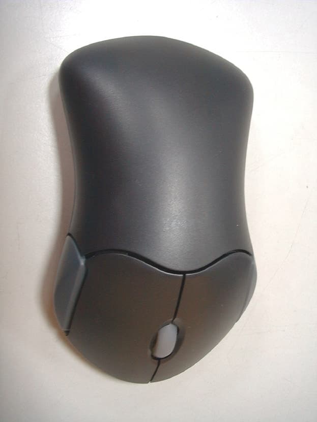
Click to zoom
Application Details
- Equipment Class
- DXX - Part 15 Low Power Communication Device Transmitter
- Date of Grant
- Sep 12, 2001
- Application Purpose
- Original Equipment
- Date of Application
- Sep 12, 2001
- Equipment Note
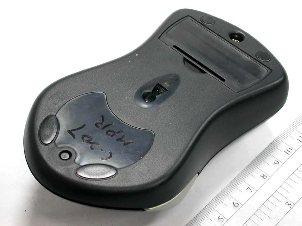
- Wireless Mouse
- Frequency Range
- 27.04000000 - 27.10000000
- Company
- Memorex Products, Inc.
- Country
- United States
Documents & Files
Document Text
Text extracted from the exhibit documents filed with the FCC. Open a document above to read the original.
Users Manual
1 Memorex RF ScrollPro Mouse 1994-2001 Copyright All Rights Reserved FCC Statement on CLASS B Dear Memorex Consumer Congratulations ! You just purchased the perfect Wireless Mouse! Please take some time to read the following instructions carefully. The Memorex RF ScrollPro Mouse signal is transmitted through electromagnetic energy from transmitter to the receiver. The output power is low but strong enough to have a good detection for the receiver. Therefore, the harm from radioactivity to the human body is negligent. Note: This equipment has been tested and found to comply with the limits for a CLASS B digital device, pursuant to Part 15 of the FCC Rules. These limits are designed to provide reasonable protection against harmful interference when the equipment is operated in a residential installation. This equipment generates, uses, and can radiate radio frequency energy and if not installed and used in accordance with the instruction manual may cause harmful interference to radio communications. However, there is no guarantee that interference will not occur in a particular Installation .If this equipment does cause interference to radio or television reception, which can be determined by turning the equipment off and on, the user is encouraged to try to correct the interference by one or more of the following measures: * Reorient or relocate the receiving antenna. * Increase the separation between the equipment and receiver. * Connect the equipment into an outlet on a circuit different from that to which the receiver is connected. * Consult the dealer or an experienced radio TV technician for help. This device complies with Part 15 of the FCC Rules. Operation is subject to the following two conditions: (1) this device may not cause harmful interference. 2 (2) this device must accept any interference received, including interference that may cause undesired operation. 1. Hardware Installation 1-1.Installing a Mouse with a PS/2 Connector Turn off the computer before connecting or disconnecting your mouse. Connect the PS/2 Mouse to the PS/2 port on your computer. 1-2.Installing a Combo (PS/2 to USB) Mouse Connect the PS/2 to USB adapter to the PS/2 Mouse Connector. Plug the USB adapter into an available USB port on your computer. 1-3.Select and Set ID 1-3-1.Plug in receiver connector to your computer to turn on LED indicator. After pressing the ID setting button on the back of receiver, the LED Light begins flashing. You are now ready to set the Mouse ID setting: 1-3-2.To set the Mouse ID setting do one of the following: 1)ID one: Press the ID defining button (on the back of mouse) 2)ID two: Press command key (usually the left button) first, then ID defining button. Release ID defining button first, then command key. 3)ID three: Press pop-up key (usually the right button) first, then ID defining button. Release ID defining button first, then pop-up key. 4)ID four: Press wheel button first, then ID defining button. Release ID defining button first, then wheel button. 1-3-3.After you select the ID and send the signal from the mouse, the mouse receiver will receive and automatically detect and create a working link. After you successfully finish the ID setting, the LED indicator on the receiver will confirm every move of the mouse by flashing. If you want to re-define the ID, will simply begin the process again by pressing the ID button of the receiver first. *Note: once you change the batteries, don't forget to reset the ID. 3 2. Mouse Driver Installation Mouse software Windows 95, Windows 98, Windows NT 3.51, Windows NT 4.0, Windows 2000 and Windows ME. Before installing any software under Windows NT 4.0, we strongly recommend you create an Emergency Repair Disk using the Repair Disk utility provided by the system (RDISK.EXE). Please note that USB mice are only supported under Windows 98 , Windows 2000 and Windows ME. 2-1. Standard Installation for Windows 95, Windows 98, Windows NT 4.0, Windows 2000,and Windows ME. Insert the CD into your computers CD-ROM drive. The program will auto-launch. Follow the on-screen instructions. If the program fails to auto launch Use Windows Explorer to locate Run Setup.exe on the CD. Double click the file to launch the installation. Follow the on-screen instructions. 2-2. Drivers Only Installation You can load device drivers without running the Setup program. If you load the device drivers this way however, the Setup program will be loaded automatically after the drivers install. Please execute the following steps to perform a drivers-only installation for Windows 2000: 1) Click on the "Start" button on the Windows Desktop. 2) Select "Settings", then "Control Panel". 3) From the Control Panel, double click on the "System" icon. 4) From the System Properties, click on the "Hardware" tab. 5) Click on the "Device Manager" button. 6) From the Device Manager, double click the "Mouse" icon. 4 7) Double click on the Mouse Type icon. 8) From the Mouse Properties dialog box, click on the "Driver" tab, then click on the "Update Driver" button. 9) From the "Update Device Driver Wizard", click the "Next" button. 10) Click on the radio button next to: "Display a list of the known drivers for this device so that I can choose a specific driver" 11) Click on the "Next" button. 12) Click on the "Have Disk" button. 13) When prompted, click the "Browse" button. 14) From the "Locate File" dialog box, go to the "Setup\Drivers\Win2kdrv" folder on the Mouse Driver CD. 15) Click the "Open" button. 16) From the "Install From Disk" dialog box, click the "OK" button. 17) Under "Models", select the correct model that matches the pointing device type and click on the "Next" button. 18) If the "Update Driver Warning" appears, click on the "Yes" button. 19) Click on the "Next" button. 20) Windows should now copy the updated mouse drivers to the system. 21) Click on the "Finish" button. 22) Click on the "Close" button. 23) Windows should now ask you to restart the system for the changes…
Text truncated - open the document above for the full version.
Block Diagram
1234 A B C D 4321 D C B A 1 150 16 . ,235 , , , 2 A 18-Jun-200115:43:20D:\WIN_BACK\CHIC\MOUSE\C141\\C141RX.SCH Title Size:Number: Date:File: Revision: SheetofTime: A4 C-141 RX-BLOCK DIAGRAM Chic ANTENNA MIXER IF FILTER DETECTOR CRYSTAL OSC 455KHz (RF RX PARTS) DATA S1 CHANNEL SW MICRO CONTROLLER RF LED LINK BUTTON EEPROM PS2/USB ADAPTOR PS2 USB 27.5Mhz27.55Mhz 1234 A B C D 4321 D C B A 1 150 16 . ,235 , , , 2 A 18-Jun-200115:42:53D:\WIN_BACK\CHIC\MOUSE\C141\\C141TX.SCH Title Size:Number: Date:File: Revision: SheetofTime: A4 C-141 TX-BLOCK DIAGRAM Chic BATTERY 1.5V BATTERY 1.5V 6MHz VCC VCC VCC VCC RF TX PARTS VCC ENABLE DATA OUT X AXIS SENSER ENCODER ENCODER SENSER Y AXIS CPU 5 BUTTON VCC ENCODER Z AXIS BATTERY LOW DETECTOR VCC ANTENNA S1 CHANNEL SW 27.095Mhz 27.045Mhz
Cover Letter(s)
From: report [[email protected]] Sent: Monday, September 10, 2001 12:10 AM To: Barbara Judge Subject: Re: FCC ID: PSJMX4300RF Follow Up Flag: Follow up Due By: Thursday, September 13, 2001 5:00 PM Flag Status: Flagged Dear Barbara, In response to your e-mail on 2001/08/30. Q1. See attachment e-file for 4300FR-Q1.pdf Q2. See attachment e-file for 4300FR-Q2.pdf Best regards, Jack Tsai Traning Research Co., Ltd. e-mail: [email protected] ----- Original Message ----- From: Barbara Judge <[email protected]> To: <[email protected]> Cc: Mike Kuo <[email protected]> Sent: Thursday, August 30, 2001 5:29 AM Subject: FCC ID: PSJMX4300RF > Dear Mr. Tsai, > > Thank you for your recent application for Equipment Authorization on behalf > of your client, Memtek Products. The following issues must be addressed > before processing can be completed. > > 1. Please provide revised Users Manual which includes a cautionary > statement to the user, in accordance with 15.21, that changes or > modifications not expressly approved by the party responsible for compliance > could void the user's authority to operate the equipment. > > 2. The test report indicates that a Bi-Log antenna was used to make all > radiated measurements. The FCC requires that measurements made below > 30MHz be made with a loop antenna. Please submit data accordingly. > > Please provide the above detailed items so that processing on your > application may proceed. > > The items indicated above must be submitted before processing can > continue > on the above referenced application. Failure to provide the > requested > information within 60 days of the original e-mail date may result in > > application dismissal and forfeiture of the filing fee. Also, please > note > that partial responses increase processing time and should not be > submitted. > Any questions about the content of this correspondence should > be directed to the e-mail address listed below the name of the > sender. > > > Best Regards, > Barbara > _______________________________________ > Barbara L. Judge > Vice President > Compliance Certification Services > Designated TCB and CAB > 561F Monterey Road > Morgan Hill, CA 95037 > 408-463-0885 ext.104 > Fax: 408-463-0888 > e-mail: [email protected] > http://www.ccsemc.com
ID Label/Location Info
LABEL Format: This device complies with Part 15 of the FCC Rules Operation is subject to the following two conditions: (1) This device may not cause harmful interference, and (2) This device must accept any interference received, including interference that may cause undesired operation Model No.:MX4300RF FCC ID:PSJMX4300RF LABEL Size: 39 x 34 mm LABEL Position:
Test Report
Test Report -------------------------------------------------------------------------------- 2/16 Report No.: C3115292 Training Research Co., Ltd., TEL: 886-2-26935155, Fax: 886-2-26934440 Contents Chapter 1 Introduction Description of EUT...................................................................................................................3 Configuration of Test Setup......................................................................................................4 List of Support Equipment........................................................................................................5 Chapter 2 Conducted Emission Test Test Condition and Setup..........................................................................................................8 Chapter 3 Radiated Emission Test Test Condition and Setup..........................................................................................................9 Radiated Test Placement..........................................................................................................11 Appendix A : Radiated test result...................................................................................................................12 Appendix B : Band Edge of Measurement.....................................................................................................15 Test Report -------------------------------------------------------------------------------- 3/16 Report No.: C3115292 Training Research Co., Ltd., TEL: 886-2-26935155, Fax: 886-2-26934440 Chapter 1Introduction Description of EUT: EUT:Wireless Mouse Model No.:MX4300RF FCC ID:PSJMX4300RF Frequency Range:27.04 – 27.10 MHz Power Type:Powered by two 1.2VDC batteries This wireless mouse use advancing transmission technology to allow comfortable use. However, occasionally outside sources may cause interference. Test method: All measurements contained in this report were performed according to the techniques described in Measurement procedure ANSI C63.4 – 1992. Pretest was found that the emission of operating mode is worse than standby mode. So, The final test is made at the operating mode. While testing, the EUT was made to transmit continuously, which transmitted the maximum emission. The test placement as the photographs showed is the worst case emission placed. (If the emission is close to the ambient, the resolution BW and view resolution will be reduced and the data will be recorded by detection of maximum hold peak mode.) The testing configuration of test setup is showing in the next page. Test Report -------------------------------------------------------------------------------- 4/16 Report No.: C3115292 Training Research Co., Ltd., TEL: 886-2-26935155, Fax: 886-2-26934440 Configuration of Test Setup (Operating mode) Connections: EUT: Put two AAA size, 1.2V batteries into the battery cell of EUT, powers the subject device. The EUT does not be connected with any product. Located Remotely Rx USB Joystick USB Mouse Keyboard Monitor Modem PrinterPC Power EUT (Tx) Test Report -------------------------------------------------------------------------------- 5/16 Report No.: C3115292 Training Research Co., Ltd., TEL: 886-2-26935155, Fax: 886-2-26934440 List of Support Equipment Conducted (Radiated) test: PC:HP Brio 85xx 6/350 Model No.:D6928A Serial No. :SG91801552 FCC ID:N/A, Doc Approved :3872H013 Power type:100 ~ 230VAC / 50 ~ 60Hz, 5A, Switching Power cord :Non-shielded, 2.33m long, Plastic, No ferrite core Monitor :HP 15’ Color Monitor Model No.:D2832A Serial No.:KR91379759 FCC ID:N/A, Doc Approved :4872A167 Power type:100 ~ 240 VAC / 50 ~ 60 Hz, Switching Power cord:Shielded, 1.80m long, No ferrite core Data cable :Shielded, 1.50m long, with two ferrite cores Printer:HP Model No.:C2184A Serial No.:SG55T1P1KY FCC ID:N/A, Doc Approved Power type:Linear Power cord:Non-shielded, 1.90m long, No ferrite core Data cable :Shielded, 1.8m long, No ferrite core Test Report -------------------------------------------------------------------------------- 6/16 Report No.: C3115292 Training Research Co., Ltd., TEL: 886-2-26935155, Fax: 886-2-26934440 Keyboard:HP Model No.:SK-2501K Serial No.:MR81008879 FCC ID:GYUR38SK :3862A621 Power type:By PC Data cable :Shielded, 1.73m long, with ferrite core Mouse:HP Model No.:M-S34 Serial No.:LZB90910464 FCC ID:DZL211029 :4862A011 Power type:By PC Power cord:Non-shielded, 1.88m long, No ferrite core Modem:ACEEX Model No.:XDM41414 Serial No.:964111217 FCC ID:IFAXDM1414 Power type:Linear Power cord:Non-shielded, 1.9m long, No ferrite cord Data cable :RS232, Shielded, 1.2m long, No ferrite core RJ11C x 2, 7’ long non-shielded, No ferrite core Test Report -------------------------------------------------------------------------------- 7/16 Report No.: C3115292 Training Research Co., Ltd., TEL: 886-2-26935155, Fax: 886-2-26934440 USB Mouse:Logitech Model No.:M-BA47 Serial No.:LZE92250027 FCC ID:N/A, Doc Approved :4872A220 Power type:Powered by PC Data Cable:Shielded, 1.5m long, Plastic hoods, No ferrite bead USB Joystick:Padix Model No.:QF-305U Serial No.:8100848 FCC ID: N/A, Doc Approval Power type:Powered by PC Data Cable:Shielded, 1.5m long, No ferrite bead Receiver :Memtek Products, Inc. Model No.:MX4300RF Serial No.:N/A FCC ID: N/A, Doc Approval Power type:Powered by PC Data Cable:Shielded, 1.45m long, No ferrite bead Test Report -------------------------------------------------------------------------------- 8/16 Report No.: C3115292 Training Research Co., Ltd., TEL: 886-2-26935155, Fax: 886-2-26934440 Chapter 2Conducted Emission Test Test Condition and Setup: All the equipment is placed and setup according to the ANSI C63.4 – 1992. The EUT is assembled on a wooden table, which is 80 cm high, is placed 40 cm from the back-wall, which is a vertical conducting plane. One LISN is for EUT, the other LISN is for support equipment. They are all placed on the conductive ground. The EUT’s LISN connect a line switch box for s…
Text truncated - open the document above for the full version.
Test Report
FCC ID : PSJMX4300RF Peak Power Measurement (Frequency Band: 26.96 ~ 27.28) 1. Test Setup 3M EUT 1M Ground Plane HP 8546A Spectrum Analyzer Figure 1 2. Test Procedure a. The EUT was setup in the anechoic chamber as shown above. b. The loop antenna was located upon its plane vertical, 3-meter distance from the EUT. The center of the loop is 1-meter above the ground plane. c. In order to find the maximum radiation, the EUT was rotated 360 . The measuring antenna was rotated about its axis at each azimuth about the EUT. 3. List of Test Instruments Instrument Name Model No. Brand Serial No. Last time Next time EMI Receiver 8546A H P 3520A00242 10/01/00 10/01/01 RF Filter Section 85460A H P 3448A00217 10/01/00 10/01/01 Active Loop Antenna 6502 EMCO 2777 07/20/01 07/20/02 4. Test Results Frequency: 27.04 MHz (CH 1) Antenna Polarity Reading Amplitude Correction Factors Corrected Amplitude Limit Margin dBμV dB/m dBμV/m dBμV/m dB Horizontal -13.00 47.08 80 Horizontal > Vertical Frequency: 27.10 MHz (CH 2) Antenna Polarity Reading Amplitude Correction Factors Corrected Amplitude Limit Margin dBμV dB/m dBμV/m dBμV/m dB Vertical -13.00 42.61 80 Horizontal < Vertical Band Edge of Measurement: (Frequency Band: 26.96 ~ 27.28) Test Result: CH1 CH2
Test Setup Photos
To: Date:3/7/2014 13:19:18 [email protected] Message: This is to notify that this application TC442976 granted on 11/19/2013 is approaching the short-term confidentiality release date of 03/15/2014. If no action is taken, any files marked as short-term confidential will automatically become viewable on the FCC website. Subject: Short-Term Confidentiality Release Notification, Form 731 Confirmation Number: TC442976 FCC ID: P25D232263A4512C
Contact Information
Applicant
Angela Thomas(Product Manager)
Technical Contact
Training Research Co., Ltd.Jack Tsai
[email protected]886-2-26935155
No. 2, Lane 194, Huan Ho Street, · Taipei Hsien, · Taiwan
Test Firm
Training Research Co., Ltd.Jack Tsai
Technical Specifications
| # | Rule Parts | Frequency Range | Power Output |
|---|---|---|---|
| 1 | 15C | 27.04 MHz - 27.1 MHz | - |
Other Applications from Memorex Products, Inc.
PSJMX4420RF
Mar 21, 2004WIRELESS OPTICAL MOUSE
Equipment Class
DXX - Part 15 Low Power Communication Device Transmitter
PSJMX4350RF-1
May 26, 2003Wireless Mouse
Equipment Class
DXX - Part 15 Low Power Communication Device Transmitter
PSJMX4350RF
Sep 12, 2001Wireless Optical Mouse
Equipment Class
DXX - Part 15 Low Power Communication Device Transmitter