PSJMX4420RFWIRELESS OPTICAL MOUSE
Memorex Products, Inc.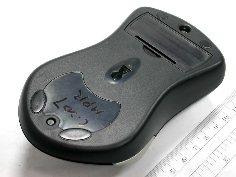
Click to zoom
Application Details
- Equipment Class
- DXX - Part 15 Low Power Communication Device Transmitter
- Date of Grant
- Mar 21, 2004
- Application Purpose
- Original Equipment
- Date of Application
- Mar 21, 2004
- Equipment Note
- WIRELESS OPTICAL MOUSE
- Frequency Range
- 26.96000000 - 27.28000000
- Company
- Memorex Products, Inc.
- Country
- United States
Documents & Files
Document Text
Text extracted from the exhibit documents filed with the FCC. Open a document above to read the original.
Users Manual
6 Button Programmable Mouse Wireless Office ScrollPro GUIDE user's user's Version1.0 Optical Mouse USB & PS/2RF- Wireless A. Introduction Congratulations on your purchase of the Wireless Office ScrollPro Optical Mouse! This mouse uses optical technology instead of a dust-collecting roller ball to track movements. Signals are sent to a receiver by means of radio frequency (RF) in order to reduce inter- ference from other wireless devices such as TV remote controls and cordless phones. Please take time to read the following instructions carefully. They will help you get full use of your mouse and keep it working reliably for many years. B. What’s in this package • Wireless Office ScrollPro Optical Mouse (Part # 32022384) • RF Wireless Receiver •ScrollPro Mouse Series Driver CD • 2 AAA Batteries C. System Requirements •IBM or compatible PC •Available USB 1.1/2 or PS/2 port •CD-ROM or DVD drive (for driver installation. Users without an optical disc drive can download the drivers from the Memorex website at www.Memorex.com) •Microsoft Windows 98SE, Windows Me Windows 2000, or Windows XP operating systems. D. Preparing the Wireless Office ScrollPro Optical Mouse Be sure to follow the installation steps in the correct order so that your mouse works properly. Step 1: Insert the batteries. •Turn the mouse over to find the battery compartment. Lift the cover by pressing in the thin plastic strip just below the half-circle indentation and pulling up. Bottom View of Mouse Channel Slide Switch Battery Compartment • Use the slide switch located inside the battery compartment to select either channel 1 or channel 2 for the RF transmission. Remember which number you choose because you will set the receiver switch to the same channel number later. • Insert the two AAA batteries (included) into the compartment. Follow the polarity signs (+ and -) in the battery compartment so the batteries face the correct direction. Inserting the batteries in the wrong direction may damage both the mouse and the batteries. • Replace the battery compartment cover by first inserting the two bottom tabs into their holes and lightly pressing down. • Make sure your computer is turned off. • Connect the receiver to the PC by plugging the green PS/2 connector at the end of the receiver to the mouse port of the computer or remove the green PS/2 connector and use the USB connector in an available USB port on the computer. Bottom View of Receiver Slide Switch Setting of Receiver Step 2: Set up the Receiver • Turn the receiver over and find the RF channel slide switch. Select the samechannel, either channel 1 or channel 2, that you selected on the mouse before you inserted the batteries. USB to PS/2 Adapter Receiver • Set the receiver flat on a surface and follow these guidelines: o Leave a minimum of 8 inches of clearance between the receiver and other electronic devices. o Leave a minimum of 8 inches of clearance between the receiver and the monitor. o The mouse can operate at a range of up to 6 feet from the receiver. o The receiver should rest on a non-metallic surface for best reception. Step 3: Synchronizing the Receiver and the Mouse. The receiver and the mouse each contain two channels, and each channel contains 256 distinct ID codes that are randomly selected when you press the ID button on the Receiver. This ID-recognition function helps protect against interference from other wireless devices in the same environment. After you have selected the same channel on both the mouse and the receiver, the next step is to match the IDs of the mouse and receiver through the synchronization process so that they can communicate with each other. • Turn the computer on. • Press once on the ID button on the top of the receiver. The green LED light below the button will start to blink slowly. ID Button of Receiver ID Button • Turn the mouse over and find its ID button near the top. Press the ID button with a blunt pointed object such as the tip of a ballpoint pen or a bent paper clip and hold the button down until the blinking light on the receiver stops blinking and remains a steady green. This may take up to 20 seconds. ID button of Mouse IMPORTANT: If 30 seconds pass before you find and press the mouse ID button, you must restart the process again by pressing the ID button on the receiver until the light blinks and once again find and hold down the ID button on the bottom of the mouse. E. Using the Mouse The Wireless Office Scroll Pro Optical Mouse uses light to sense movement. Use the mouse on an opaque surface. The optical mouse cannot work on a glass, translucent, or reflective surface that deflects the light. The mouse goes into a sleep or suspend mode after 10 minutes. The blue light at the rear of the mouse turns off to indicate that the mouse is in its sleep mode. Move the mouse or click the scroll button (suggested) or one of its other buttons to wake it. You may notice that the mouse moves the cursor on the screen twice as fast as a standard mouse does. The mouse moves the cursor at 800 dots per inch (dpi) while a standard mouse moves the cursor at only 400 dpi. You can change the cursor movement speed by using the mouse properties in the CONTROL PANEL under MY COMPUTER. • Verify that the mouse and receiver are properly synchronized by moving the mouse around on a flat surface and clicking a button or two. If the green LED on the receiver blinks fast and steadily with the movement of the mouse, the mouse and receiver are properly communicating. • If the receiver does not respond to movement of the mouse and you have repeated the synchronization process, check to see if the batteries are properly installed and that both the mouse and the receiver are set to the same channel number, then repeat the process again. If the mouse is still not working properly, check the "Troubleshooting" section for tips on how to solve your problem. • If you find interference from other wireless products such as other wireless mouse users nearby,…
Text truncated - open the document above for the full version.
Block Diagram
1234 A B C D 4321 D C B A 1 150 16. ,235 ,, , 2 A 18-Mar-200411:16:13D:\CHIC\\\\MOU\0213 \TX\RF Block-tx.DDB - Documents\RF Block-tx.sch Title Size:Number: Date:File: Revision: SheetofTime: A4 RF OPTICAL MOUSE BLOCK DIAGRAM ANTENNA BATTERY 1.5V BATTERY 1.5V VCC VCC VCC 2.2V 2.2V VCC DC-DC CONVERTER POWER AMP RF TX PARTS ENABLE DATA OUT Optical SENSER SW L SW R SW M SW RB4 (OPTION) SW RB5 (OPTION) CPU Text X Y SW1 SW-SPDT X11 27.095MHz X20 27.045MHz SW RB6 (OPTION) SW RB7 (OPTION) SW RB8 (OPTION) ENCODER Z X1 18.432MHz 6MHz
ID Label/Location Info
LABEL Format: LABEL Size: 27 x 28.2 mm LABEL Position:
Operational Description
RF OPTICAL MOUSE OPERATIONAL DESCRIPTION Mouse 01. MCU will scan the link button and matrix line. If any signal change come from above mention. It will turn convert the data package With checking the low battery status data, and prepares turn on the RF power setting the channel switch (ch1), Touch link button link to receiver.. 02. When MCU received the signal of any key. Firstly, MCU will turn on the RF power, transmitter button or MOUSE data. 03. Power amplifier is to support enough current to drive the antenna. 04.. Matching circuit is to match the impedance between PA and antenna.. Receiver 01.When the PC power on, the receiver will start the PnP process. No-matter the interface is USB AND PS/2. 02.MCU will program power, If IC will perform the exact frequency,(27.55MHz) touch link button lock channel Frequency.. 03.When the RF signal comes (27.095 MHz), the low noise amplifier (LNA) will amplify the signal about 14 dB. 04.The adding signal to pall through mixer I will generate 455KHz intermediate frequency (IF). It means that the original signal (27.095MHz) will down convert to 455KHz.. 05.IF1 filter is performing a filtering function of 455KHz (IF1). 06.When the L0 27.55MHz signal pall through the 1st mixer, it will generate the 1st IF1 455KHz. 07.After the IF1 amplifier will work for an AGC (auto gain control) function, and the signal more stable. 08.A 455KHz resonator will perform the LO function. 09.When the IF1 (455KHz) pall through discriminator, the demodulating signal will come out. We called it base band signal. 10.AF AMP will work as a data slicker, it amplify the signal to 8quare wave digital signal. 11.This digital signal will send to MCU. MCU will sample the signal to check it is valid or not. 12.IF the signal it valid, MCU will convert the signal of the interface to PC. NO-matter is PS2 let PC to do their exact activity. Mouse Antenna Spec
Schematics
1234 A B C D 4321 D C B A 150 16F 235 V 1.1 4-Mar-2004 15:31:58 Title Size:Number: EPC-207B0566 Date:File: EPC-20700368 Revision: Sheet1 OF 4Time: A4 C-207 2 Channel Transmitter Front BULE LIGHT R3 3.3M R2 3.3M R4 1K R1 X1 18.432mhz C1 0.1uF LED1 5mm +C3 100uF V5 12 34 P1 ENCODER R5 10K R6 10K SW2 R SW5 SW1 M SW4 ID SW6 SW3 L V3 D5 BAV70 D4 B A V 7 0 D6 BAV70 GND PD SDIO SCLK OSC_IN OSC_OUT R_BIN VDDREFA REFB XY_LED XA XB YB YA GND 7 13 14 11 9 1 16 15 12 8 6 2 3 4 5 10 U1 ADNS 2051 + C9 10uF R24NC (0 O) V3V5 21 43 65 87 109 1211 J1 HEADER 6X2 V3 Port 6 Port 6 1234 A B C D 4321 D C B A 150 16. ,235 ,, , 1.2 4-Mar-2004 15:36:58 Title Size:Number: EPC-207B0564 Date: Revision: Sheet2 of 4Time: A4 C-207 2 Channel Transmitter Behind (ADNS2051) RA2 1 RA3 2 RTCC 3 MCLR 4 GND 5 RB0 6 RB1 7 RB2 8 RB3 9 RB4 10 RB5 11 RB6 12 RB7 13 VCC 14 SC0 15 SC1 16 RA0 17 RA1 18 U2MDT2010-ES C6 1uF R13 51K VCC R5 330K R6 330K V3 X2 6.0MHz R4 1M C8 12pF C7 12pF C10 47pF R11 10 3 1 2 A1 R20 10K C30 NC C23 22pF C24 33pF C25 30pF R23 1.2K R25 47K Q21 3904 Q20 3904 R26 100K C32 1uF Q22 3904 C22 8pF R27 47 C20 1000P Q3 A733 R15 10K V3 V3 C31 1uF C9 20pF V3V5 R A 2 R7 330K R8 330K R9 330K G N D 2 SW 1 VO 3 U4 AIC1638-27 12 D2 RB420D L1 330uH +C13 47uF + C14 47uF V3VCC G N D 2 SW 1 VO 3 U5 RT9261 36CX 12 D3 RB420D L2 330uH + C15 47uF + C16 47uF V5 VCC RA2 X20 27.095MHz X11 27.045MHz S1 SGB-12 R28 NC C26 V5V3 C17 1uF C18 1uF 1 2 D7 5.1V/5mAR1 NC VCC BT1 BATTERY NC 21 43 65 87 109 1211 J3 HEADER 6X2 Vin 1 G N D 2 Vout 3 U6 S80723 R24 100 LED2 RED VCC D111N4148 D121N4148 D131N4148 SW7 PB6 SW8PB7 SW9PB8 C33 8P R30 NC BLUE 0805 LED1 BLUE 0805 LED3 V5 R31 22 123456 A B C D 654321 D C B A 1 15016. ,235 ,, , 1 1.2 4-Mar-2004 15:39:16 Title Size:Number: EPC-207E0374 Date:File:EPC-207E0374 Revision: SheetofTime: A4 C-207 RX 2 CH C1 0.1uF + C4 10uF VCCVCC D- D+ A0 1 A1 2 A2 3 GND 4 SDA 5 SCL 6 TEST 7 VCC 8 U2 AT24C02 VCC R2 560 R14 NC D+/SCLK 13 P1.1 14 XTALIN 9 XTALOUT 10 VCC 11 VREG 8 P00 1 P01 2 P02 3 P03 4 P04 18 P05 17 P10 5 P06 16 VSS 6 P07 15 VPP 7 D-/SDATA 12 U1 CY7C63723 DATA SW1 SW-PB R5 1.3K CH1 CH2 C3 1000pF C6 27pFC7 27pF C8 0.1uF C9 0.1uF C10 0.1uF C11 0.01uF R7 27K R8 3.3K X3 27.550MHz X2 27.50MHz 12 F1 455KHZ FILTER R9 4.7K C12 22pF X4 455C28 R10 100K C14 0.1uF D1 1N4148 R11 NC OSCB 1 OSCE 2 MBCO 3 VCC 4 IFI 5 DEC1 6 DEC2 7 BUAD 8 AUTO 9 FI 10 FO 11 SQI 12 SCAN 13 MUTE 14 GND 15 MOCI 16 MC3361 U3 MC3361 Q4 2N3904 DATA +C13 10uF VCC C5 NC (100PF) ANT R12NC R13NC LED V+ L2 BEAD 600 or NC 1 2 3 4 5 WAFER HEADER 5 SHIELD G Q3 2N3904 R1 22R VCC 12 J1 NC VCC1 R6 NC C15 4700pF SW2 SW SPDT L1A 4.7 uH INDUCTOR C20 0.1uF C18 104 C17 100P C19 100P 1 2 JP2 NC
Test Report
Test Report ----------------------------------------------------------------------------- 2/12 Report No.: C3115801 Training Research Co., Ltd., TEL: 886-2-26461146, Fax: 886-2-26461778 Contents Chapter 1 Introduction Description of EUT ................................................................................................................... 3 Configuration of Test Setup ...................................................................................................... 4 List of Support Equipment ........................................................................................................ 4 Chapter 2 Conducted Emission Test Test Condition and Setup .......................................................................................................... 5 Chapter 3 Peak Power Measurement (Frequency Band: 26.96 ~ 27.28) Test Setup .................................................................................................................................. 6 Test Procedure........................................................................................................................... 6 Chapter 4 Radiated Emission Test Test Condition and Setup .......................................................................................................... 7 Radiated Test Placement ........................................................................................................... 8 Appendix A: Peak Power and Radiated test result ......................................................................................... 9 Appendix B: Band Edge of Measurement ..................................................................................................... 11 Test Report ----------------------------------------------------------------------------- 3/12 Report No.: C3115801 Training Research Co., Ltd., TEL: 886-2-26461146, Fax: 886-2-26461778 Chapter 1 Introduction Description of EUT: This is a class II change application. EUT : Wireless Optical Mouse Model No. : MX4420RF, 32022384 Product name : RF Office ScrollPro Frequency Range : 26.96 – 27.28 MHz Power Type : Transmitter: Powered by two 1.5VDC AA batteries *This EUT only has one channel (with 256 IDs): 27.0950 MHz Test method: Pretest was found that the emission of operating mode is worse than standby mode. So, The final test is made at the operating mode. During the measurement, the EUT was at operating mode. The radiation pretest was found out this mode was the worst case and we only recorded this data in this report. While testing, the EUT was made to transmit continuously and adjusted at a position, which transmitted the maximum emission. The test placement as the photographs showed is the worst case emission placed. (If the emission is close to the ambient, the resolution BW and view resolution will be reduced and the data will be recorded by detection of maximum hold peak mode.) The testing configuration of test setup is showing in the next page. Test Report ----------------------------------------------------------------------------- 4/12 Report No.: C3115801 Training Research Co., Ltd., TEL: 886-2-26461146, Fax: 886-2-26461778 Configuration of Test Setup EUT: Put three AA size, 1.5V battery into the battery cell of EUT, powers the subject device. The EUT does not be connected with any product. List of Support Equipment Conducted (Radiated) test: N/A EUT Test Report ----------------------------------------------------------------------------- 5/12 Report No.: C3115801 Training Research Co., Ltd., TEL: 886-2-26461146, Fax: 886-2-26461778 Chapter 2 Conducted Emission Test Test Condition and Setup: All the equipment is placed and setup according to the standard. The EUT is assembled on a wooden table that is 80 cm high, is placed 40 cm from the back-wall that is a vertical conducting plane. One LISN is for EUT, the other LISN is for support equipment. They are all placed on the conductive ground. The EUT’s LISN connect a line switch box for selecting L1 or L2, then connect to a preamplifier and Spectrum. The spectrum measured from 150KHz to 30MHz. Conducted emission levels are detected at max. peak mode. But if the max. peak mode failed or over average limit, it will be measured by QP and average detection mode using the Receiver. While testing, there is the worst-emission plot printed at peak detection mode, and there are more than 6 highest emissions relative to limit recorded. The plot is kept as the original data, not included in test report. List of test Instrument : Calibration Date Instrument Name Model No. Brand Serial No. Last time Next time Spectrum analyzer 8591EM H P 3710A01203 05/21/03 05/20/04 LISN (EUT) 3825/2 EMCO 9411-2284 07/21/03 07/20/04 LISN (Support E.) 3825/2 EMCO 9210-2007 09/03/03 09/02/04 Preamplifier CB-001 TRC 98-02 05/29/03 05/28/04 Line switch box CB-01 TRC 98-04 05/29/03 05/28/04 1dB Attenuator CAT-1 mini-circuits - - - - - - - - - 05/29/03 05/28/04 FTB-1-6 Attenuator 15542 mini-circuits 9620 03 05/29/03 05/28/04 20dB Attenuator CAT-20 mini-circuits 9620 13 05/29/03 05/28/04 3dB Attenuator CAT-3 mini-circuits 9620 14 05/29/03 05/28/04 Coaxial Cable BNC3200B-0058 Jyebao CL-05 05/29/03 05/28/04 Coaxial Cable BNC31VB-0316 Jyebao IF-01ca0069-036 05/29/03 05/28/04 50ohm terminator 370BNM NARDA PWR5W 07/21/03 07/20/04 50ohm terminator 370BNM NARDA PWR5W 07/21/03 07/20/04 50ohm terminator 370BNM NARDA PWR5W 09/03/03 09/02/04 50ohm terminator 370BNM NARDA PWR5W 09/03/03 09/02/04 The level of confidence of 95% , the uncertainty of measurement of conducted emission is +3.1/-4.84 dB . Test Result: Pass Test Report ----------------------------------------------------------------------------- 6/12 Report No.: C3115801 Training Research Co., Ltd., TEL: 886-2-26461146, Fax: 886-2-26461778 Chapter 3 Peak Power Measurement (Frequency Band: 26.96 ~ 27.28) Test Setup: 1. Test Setup: 2. Test Procedure: a. The EUT was setup in the anechoic chamber as shown above. b. The loop antenna was …
Text truncated - open the document above for the full version.
Test Setup Photos
Radiated Test Placement: (Photographs)
Contact Information
Applicant
Angela Thomas(Product Manager)
Test Firm
Training Research Co., Ltd.Jack Tsai
Technical Specifications
| # | Rule Parts | Frequency Range | Power Output |
|---|---|---|---|
| 1 | 15C | 26.96 MHz - 27.28 MHz | - |
Other Applications from Memorex Products, Inc.

PSJMX4350RF-1
May 26, 2003Wireless Mouse
Equipment Class
DXX - Part 15 Low Power Communication Device Transmitter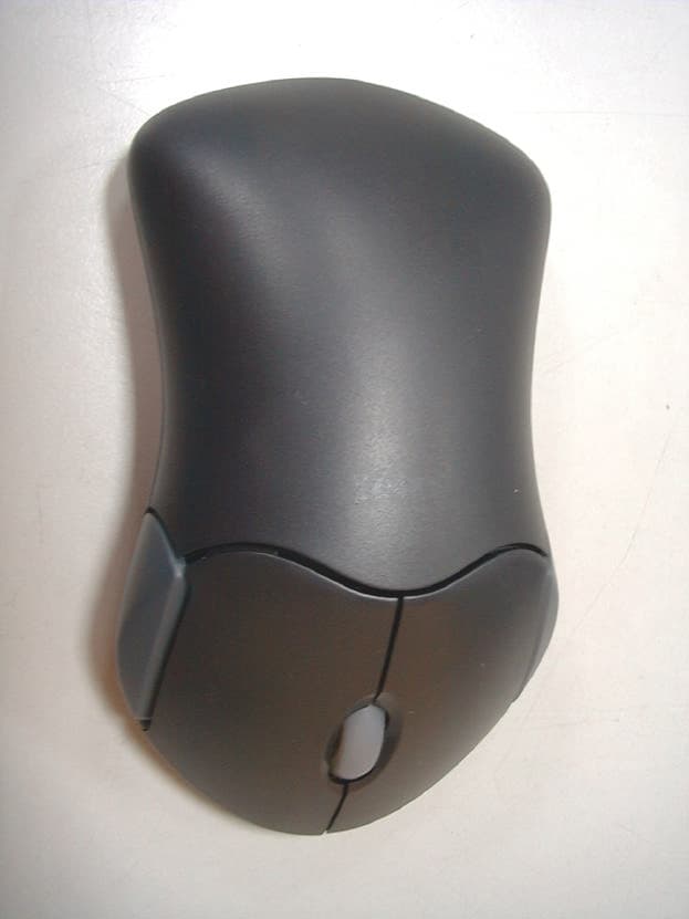
PSJMX4300RF
Sep 12, 2001Wireless Mouse
Equipment Class
DXX - Part 15 Low Power Communication Device Transmitter
PSJMX4350RF
Sep 12, 2001Wireless Optical Mouse
Equipment Class
DXX - Part 15 Low Power Communication Device Transmitter