PSN5150-TX49MICRO SLIDER
CCP Co., Ltd.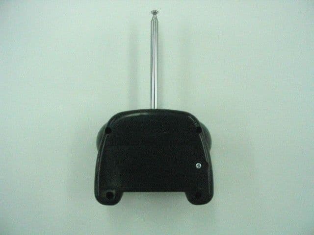
Click to zoom
Application Details
- Equipment Class
- DXX - Part 15 Low Power Communication Device Transmitter
- Date of Grant
- Aug 12, 2004
- Application Purpose
- Original Equipment
- Date of Application
- Aug 12, 2004
- Equipment Note
- MICRO SLIDER
- Frequency Range
- 49.86000000 - 49.86000000
- Company
- CCP Co., Ltd.
- Country
- Japan
Documents & Files
Document Text
Text extracted from the exhibit documents filed with the FCC. Open a document above to read the original.
Users Manual
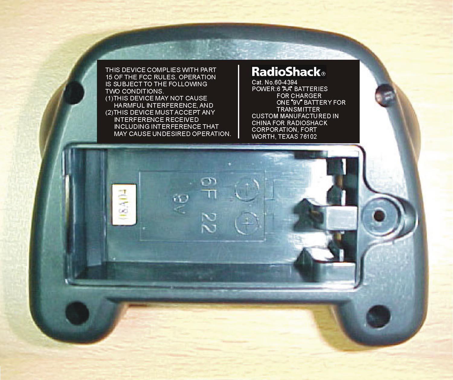
Please read this user’s guide before installing, setting up and using your new product www.radioshack.com To power your slider, you will need one 9V battery for the transmitter and six AA batteries for the slider. None are supplied, but all are available at your local RadioShack or online at www.radioshack.com.in the transmitter • Dispose of old batteries promptly and properly. Do not burn or bury batteries.• Use only fresh batteries of the required size and recommended type. • Do not mix old and new batteries, different types of batteries (standard, alkaline, or rechargeable), or rechargeable batteries of different capacities. • If you do not plan to use the toy for several days, remove the batteries. Batteries can leak chemicals that can damage electronic parts. • Batteries purchased for use in this toy may pose a hazard to children. Please check the safety notice supplied with batteries before use. Note: Actual product may vary from the images found in this document. Photos not to scale. Thank you for purchasing your Micro Slider from RadioShack. This tiny vehicle will dazzle your friends because of all the cool stunts it can do. The slider is available in two frequencies (27 and 49 MHz) so that you can race other radio-controlled vehicles. Micro Slider transmitter charger user’s guide 60-4394 micro slider in the charger1. Remove the charger’s battery compartment cover. Replace when fi nished. NOTE 2. Place the 9 volt battery in the compartment as indicated by the polarity symbols (+ and -). 1. Remove the cover. Replace when fi nished. When the transmitter’s range decreases, replace its battery. 2. Install six AA batteries into charger’s battery compartment as indicated by the polarity symbols (+ and -). Micro Slider Transmitter Charger ©2004 RadioShack Corporation.All rights reserved. RadioShack and RadioShack.com are trademarks used by RadioShack Corporation. 60-4394 07A04 Printed in China This equipment has been tested and found to comply with the limits for a Class B digital device, pursuant to Part 15 of the FCC Rules. These limits are designed to provide reasonable protection against harmful interference in a residential installation. This equipment generates, uses, and can radiate radio frequency energy and, if not installed and used in accordance with the instructions, may cause harmful interference to radio communications. However, there is no guarantee that interference will not occur in a particular installation. If this equipment does cause harmful interference to radio or television reception, which can be determined by turning the equipment off and on, the user is encouraged to try to correct the interference by one or more of the following measures: • Reorient or relocate the receiving antenna.• Increase the separation between the equipment and receiver. • Connect the equipment into an outlet on a circuit different from that to which the receiver is connected. Consult your local RadioShack store or an experienced radio/TV technician for help.If you cannot eliminate the interference, the FCC requires that you stop using your slider. Changes or modifi cations not expressly approved by RadioShack may cause interference and void the user’s authority to operate the equipment.This device complies with Part 15 of the FCC Rules. Operation is subject to the following two conditions: (1) This device may not cause harmful interference, and (2) This device must accept any interference received, including interference that may cause undesired operation. Product Micro Slider Model 60-4394 Responsible Party RadioShack 100 Throckmorton Fort Worth, TX 76102 Phone 817-415-3200 This product is warranted by RadioShack against manufacturing defects in ma-terial and workmanship under normal use for ninety (90) days from the date of purchase from RadioShack company-owned stores and authorized RadioShack franchisees and dealers. For complete warranty details and exclusions, check with your local RadioShack store.RadioShack Customer Relations 200 Taylor Street, 6th Floor, Fort Worth, TX 76102 04/04 The EPA certifi ed RBRC® Battery Recycling Seal on the nickel-cadmium (Ni-Cd) battery indicates RadioShack is voluntarily participating in an industry program to collect and recycle these batteries at the end of their useful life, when taken out of service in the United States or Canada. The RBRC program provides a convenient alternative to placing used Ni-Cd batteries into the trash or the municipal waste stream, which may be illegal in your area. Please call 1-800-THE-SHACK (1-800-843-7422) for information on Ni-Cd battery recycling and disposal bans/restrictions in your area. RadioShack’s involvement in this program is part of the company’s commitment to preserving our environment and conserving our natural resources. • Keep your slider, charger, and transmitter dry. If they get wet, wipe them dry immediately. • Use and store the slider, charger, and transmitter only in room temperature environments. • Handle the slider, transmitter, and charger carefully. Do not drop them. • Keep the slider, charger, and transmitter away from dust and dirt, and wipe them with a damp cloth occasionally to keep them looking new. • Do not play with your vehicle in the street.• Your slider may perform differently on different types of surfaces. • Do not play with the slider on hairy or carpeted surfaces, as hair or lint can damage the wheel gears. • If your slider is not performing as it should, take it to your local RadioShack store for assistance. • Driving your slider for long periods of time can generate a high heat level, which causes wear and tear on the motor. To help keep heat levels down, when your vehicle’s battery power dies, let it cool for at least 10 minutes before installing new batteries. • Do not touch the motor or batteries immediately after using the slider, as they may become hot during use. • If your slider’s motor runs, but does not respond to the transmitter, move closer to the vehicle and try …
Text truncated - open the document above for the full version.
Users Manual
Please read this user’s guide before installing, setting up and using your new product www.radioshack.com To power your Wicked Wing, you will need one 9V battery for the transmitter and six AA batteries for the Wicked Wing. None are supplied, but all are available at your local RadioShack or online at www.radioshack.com.in the transmitter • Dispose of old batteries promptly and properly. Do not burn or bury batteries.• Use only fresh batteries of the required size and recommended type. • Do not mix old and new batteries, different types of batteries (standard, alkaline, or rechargeable), or rechargeable batteries of different capacities. • If you do not plan to use the toy for several days, remove the batteries. Batteries can leak chemicals that can damage electronic parts. • Batteries purchased for use in this toy may pose a hazard to children. Please check the safety notice supplied with batteries before use. Note: Actual product may vary from the images found in this document. Images not to scale. Wicked Wing transmitter charger charging cord user’s guide 60-4395 wicked wing in the charger 2. Place the 9 volt battery in the compartment as indicated by the polarity symbols (+ and -). 1. Remove the cover. Replace when fi nished. When the transmitter’s range decreases, replace its battery. 2. Install six AA batteries into charger’s battery compartment as indicated by the polarity symbols (+ and -). Thank you for purchasing your Micro Wicked Wing from RadioShack. This tiny vehicle will dazzle your friends because of all the cool stunts it can do. The Wicked Wing is available in two frequencies (27 and 49 MHz) so that you can race other radio-controlled vehicles. 1. Remove the battery compartment cover. Replace when fi nished. NOTE transmitter charger charging cord Wicked Wing ©2004 RadioShack Corporation.All rights reserved. RadioShack and RadioShack.com are trademarks used by RadioShack Corporation. 60-4395 07A04 Printed in China This equipment has been tested and found to comply with the limits for a Class B digital device, pursuant to Part 15 of the FCC Rules. These limits are designed to provide reasonable protection against harmful interference in a residential installation. This equipment generates, uses, and can radiate radio frequency energy and, if not installed and used in accordance with the instructions, may cause harmful interference to radio communications. However, there is no guarantee that interference will not occur in a particular installation. If this equipment does cause harmful interference to radio or television reception, which can be determined by turning the equipment off and on, the user is encouraged to try to correct the interference by one or more of the following measures: • Reorient or relocate the receiving antenna.• Increase the separation between the equipment and receiver. • Connect the equipment into an outlet on a circuit different from that to which the receiver is connected. Consult your local RadioShack store or an experienced radio/TV technician for help.If you cannot eliminate the interference, the FCC requires that you stop using your Wicked Wing. Changes or modifi cations not expressly approved by RadioShack may cause interference and void the user’s authority to operate the equipment.This device complies with Part 15 of the FCC Rules. Operation is subject to the following two conditions: (1) This device may not cause harmful interference, and (2) This device must accept any interference received, including interference that may cause undesired operation. Product Wicked Wing Model 60-4395 Responsible Party RadioShack 100 Throckmorton Fort Worth, TX 76102 Phone 817-415-3200 This product is warranted by RadioShack against manufacturing defects in ma-terial and workmanship under normal use for ninety (90) days from the date of purchase from RadioShack company-owned stores and authorized RadioShack franchisees and dealers. For complete warranty details and exclusions, check with your local RadioShack store.RadioShack Customer Relations 200 Taylor Street, 6th Floor, Fort Worth, TX 76102 04/04 The EPA certifi ed RBRC® Battery Recycling Seal on the nickel-cadmium (Ni-Cd) battery indicates RadioShack is voluntarily participating in an industry program to collect and recycle these batteries at the end of their useful life, when taken out of service in the United States or Canada. The RBRC program provides a convenient alternative to placing used Ni-Cd batteries into the trash or the municipal waste stream, which may be illegal in your area. Please call 1-800-THE-SHACK (1-800-843-7422) for information on Ni-Cd battery recycling and disposal bans/restrictions in your area. RadioShack’s involvement in this program is part of the company’s commitment to preserving our environment and conserving our natural resources. • Keep your Wicked Wing, charger, and transmitter dry. If they get wet, wipe them dry immediately. • Use and store the Wicked Wing, charger, and transmitter only in room temperature environments. • Handle the Wicked Wing, transmitter, and charger carefully. Do not drop them. • Keep the Wicked Wing, charger, and transmitter away from dust and dirt, and wipe them with a damp cloth occasionally to keep them looking new. • Do not play with your vehicle in the street. • Your Wicked Wing may perform differently on different types of surfaces. • Do not play with the Wicked Wing on hairy or carpeted surfaces, as hair or lint can damage the wheel gears. • If your Wicked Wing is not performing as it should, take it to your local RadioShack store for assistance. • Driving your Wicked Wing for long periods of time can generate a high heat level, which causes wear and tear on the motor. To help keep heat levels down, when your vehicle’s battery power dies, let it cool for at least 10 minutes before installing new batteries. • Do not touch the motor or batteries immediately after using the Wicked Wing, as they may become hot during use. • If your Wicked Wing…
Text truncated - open the document above for the full version.
Block Diagram
Q3 Power Control 9V Battery U1 Encoder Q1, X1 Oscillator 49.860Mhz Q2 Amplifier Antenna
Operational Description
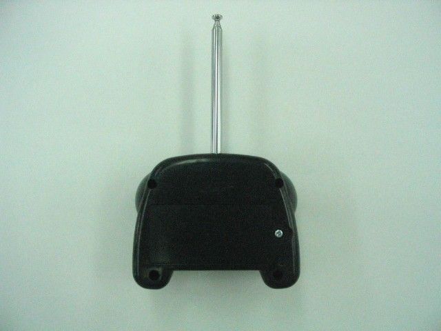
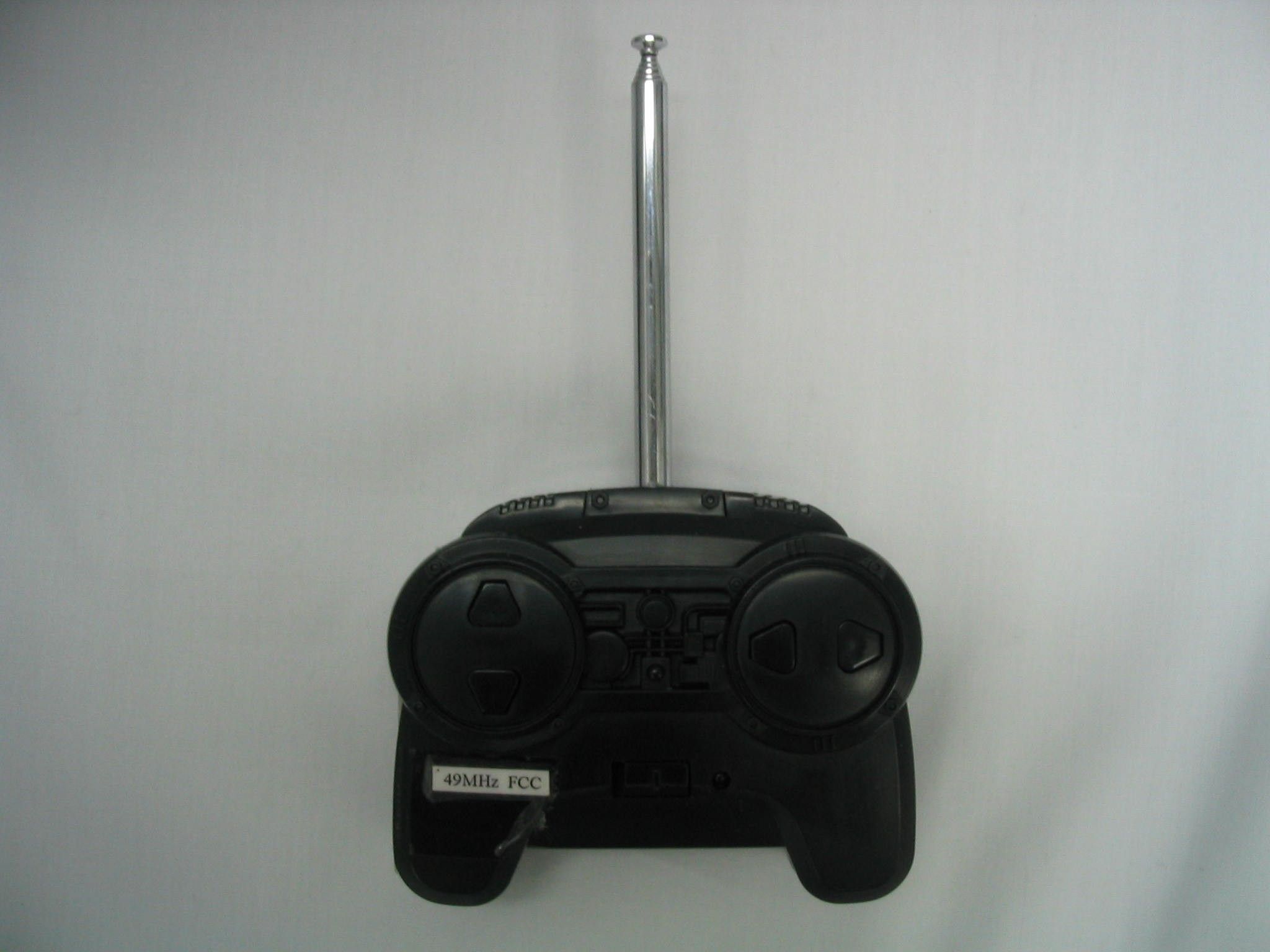
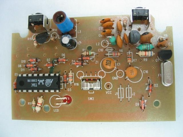
Operation Description for Micro Slider The Micro Slider is transmitter that operating at 49.860Mhz and powered by 1 x 9V side battery. There are six buttons and one on/off switch on the front of body. When the A~D button is pressed once, it will transmit a radio frequency signal for receiver go forward and backward or turn left and right. When the E~F button is pressed once, it will transmit a radio frequency for receiver slider sideways running. Referring to the transmitter circuit design, the circuit description is listed below: - U1 and associated circuit act as encoder. - Q3 and associated circuit act as power control. - Q1, X1 and associated circuit act as oscillator. - Q2 and associated circuit act as amplifier.
Test Report
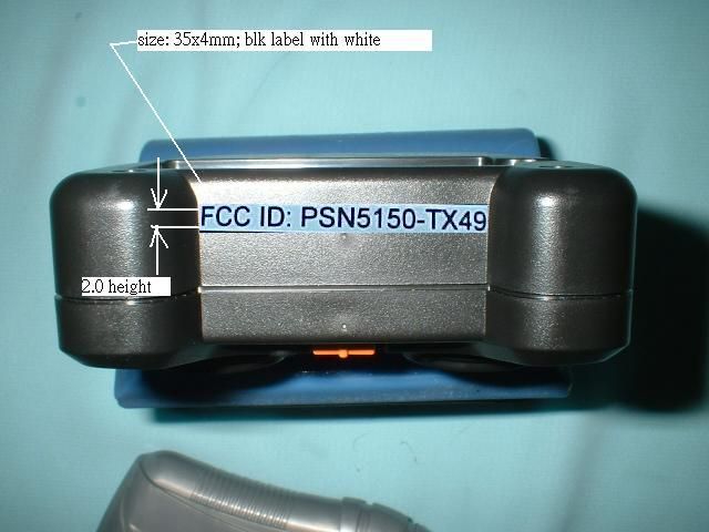
TEST REPORT This document shall not be reproduced either in full or in part except with written approval by the Authorized Representative of CMA Testing. Room 1302, Yan Hing Centre, 9-13 Wong Chuk Yeung St.., Fo Tan, Shatin, Hong Kong. Tel: (852) 2698 8198 Fax: (852) 2695 4177 E-mail: [email protected] Web Site: http://www.cmatcl.com Report No. : AE014002-001 Date : 2004 August 11 Application No.: LE208013(3) Client : CCP Co., Ltd. 3-1-8, Sakae-cho, Kawaguchi Saitama Sample Description : One(1) submitted sample stated to be follow Description Model No. Micro Slider 60-4394 Wicked Wing 60-4395 Rating : 1 x 9V battery No. of sample(s) : Two (2) piece(s) *** Date Received : 2004 July 13. Test Period : 2004 July 13 – 2004 August 10. Test Requested : FCC Part 15 Certification Test Method : FCC Rules and Regulations Part 15 – Dec 2003 ANSI C63.4 – 2001 Test Result : See attached sheet(s) from page 2 to 11. Conclusion : The submitted sample was found to comply with requirement of FCC Part 15 Subpart C. Remark : All two models are the same in circuitry and components and construction; and therefore Micro Slider model 60-4394 was chosen to be the representative of the test sample. For and on behalf of CMA Testing and Certification Laboratories Authorized Signature : Page 1 of 11 Danny Chui EMC Engineer - EL. Division FCC ID : PSN5150-TX49 TEST REPORT This document shall not be reproduced either in full or in part except with written approval by the Authorized Representative of CMA Testing. Room 1302, Yan Hing Centre, 9-13 Wong Chuk Yeung St.., Fo Tan, Shatin, Hong Kong. Tel: (852) 2698 8198 Fax: (852) 2695 4177 E-mail: [email protected] Web Site: http://www.cmatcl.com Report No. : AE014002-001 Date : 2004 August 11 Table of Contents 1 General Information........................................................................................................................ 3 1.1 General Description.................................................................................................................. 3 1.2 Related Submittal Grants.......................................................................................................... 3 1.3 Location of the test site............................................................................................................. 4 1.4 List of measuring equipment..................................................................................................... 5 2 Description of the radiated emission test........................................................................................... 6 2.1 Test Procedure......................................................................................................................... 6 2.2 Test Result...............................................................................................................................6 2.3 Radiated Emission Measurement Data....................................................................................... 7 3 Description of the Line-conducted Test............................................................................................ 8 3.1 Test Procedure......................................................................................................................... 8 3.2 Test Result...............................................................................................................................8 3.3 Graph and Table of Conducted Emission Measurement Data....................................................... 8 4 Photograph..................................................................................................................................... 9 4.1 Photographs of the Test Setup for Radiated Emission and Conduction Emission........................... 9 4.2 Photographs of the External and Internal Configurations of the EUT........................................... 9 5 Supplementary document............................................................................................................... 10 5.1 Bandwidth............................................................................................................................. 10 6 Appendices...............................................................................................................................11 Page 2 of 11 FCC ID : PSN5150-TX49 TEST REPORT This document shall not be reproduced either in full or in part except with written approval by the Authorized Representative of CMA Testing. Room 1302, Yan Hing Centre, 9-13 Wong Chuk Yeung St.., Fo Tan, Shatin, Hong Kong. Tel: (852) 2698 8198 Fax: (852) 2695 4177 E-mail: [email protected] Web Site: http://www.cmatcl.com Report No. : AE014002-001 Date : 2004 August 11 1 General Information 1.1 General Description The equipment under test (EUT) is a transmitter for Micro Slider. Operating at 49.860 MHz which is controlled by a crystal. The EUT is powered by 9V battery. There are six buttons and one on / off switch on the EUT. When the A~D button is pressed once, it will transmit a radio frequency for receiver go forward and backward or turn left and turn right. When the E~F button is pressed once, it will transmit a radio frequency for receiver slider sideways running. The brief circuit description is listed as follows : - U1 and associated circuit act as encoder. - Q3 and associated circuit act as power control. - Q1, X1 and associated circuit act as oscillator. - Q2 and associated circuit act as amplifier. The model(s) 60-4395 is the same as model 60-4394 in hardware aspect. The difference between these models is matching with different receiver. 1.2 Related Submittal Grants This is a single application for certification of a transmitter. Page 3 of 11 FCC ID : PSN5150-TX49 TEST REPORT This document shall not be reproduced either in full or in part except with written approval by the Authorized Representative of CMA Testing. Room 1302, Yan Hing Centre, 9-13 Wong Chuk Yeung St.., Fo Tan, Shatin, H…
Text truncated - open the document above for the full version.
Test Report
CMA Testing and Certification Laboratories P. of Job No.: J00002273 Bandwidth Plot Bandwidth 1
Test Report
CMA Testing and Certification Laboratories P. of Job No.: J00002273 Duty Cycle 1 CMA Testing and Certification Laboratories P. of Job No.: J00002273 Duty Cycle 2 Duty Cycle 3
Contact Information
Applicant
Asako Watanabe(Leader)
Test Firm
CMA Industrial Development Foundations LimitedStephen Lam
Technical Specifications
| # | Rule Parts | Frequency Range | Power Output |
|---|---|---|---|
| 1 | 15C | 49.86 MHz - 49.86 MHz | - |
Other Applications from CCP Co., Ltd.

PSN7850-TX27
Mar 28, 2012Radio Controlled Car
Equipment Class
DXX - Part 15 Low Power Communication Device Transmitter
PSNPG-2401
Jan 17, 20112.4G Basic Radio Control System with Servo Unit
Equipment Class
DXX - Part 15 Low Power Communication Device Transmitter
PSN5112-TX27-R
Sep 06, 2010X-Craft
Equipment Class
DXX - Part 15 Low Power Communication Device Transmitter
PSN-6100-TX27
Jul 31, 2010X-CRAWLEE
Equipment Class
DXX - Part 15 Low Power Communication Device Transmitter
PSN-5118-TX27
Apr 21, 2010Remote Controller for Toy
Equipment Class
DXX - Part 15 Low Power Communication Device Transmitter