PT5RC5200RC5200
Philips Consumer Lifestyle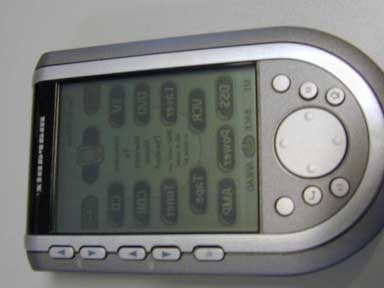
Click to zoom
Application Details
- Equipment Class
- DSR - Part 15 Remote Control/Security Device Transceiver
- Date of Grant
- Sep 05, 2001
- Application Purpose
- Original Equipment
- Date of Application
- Sep 05, 2001
- Equipment Note
- RC5200
- Frequency Range
- 417.80000000 - 417.80000000
- Company
- Philips Consumer Lifestyle
- Country
- Belgium
Documents & Files
Document Text
Text extracted from the exhibit documents filed with the FCC. Open a document above to read the original.
Users Manual
? RC5200 User Guide Automating Your Home Theater With The Marantz RC5200 ? Automating Your Home Theater With The Marantz RC5200 RC5200 Remote Control User Guide The information in this manual is copyright-protected. No part of this manual may be copied or reproduced in any form without prior written consent from Marantz America, Inc. MARANTZ AMERICA, INC. CORPORATION SHALL NOT BE LIABLE FOR OMISSIONS OR FOR TECHNICAL OR EDITORIAL ERRORS CONTAINED IN THIS MANUAL. MARANTZ AMERICA, INC. SHALL NOT BE HELD LIABLE FOR INCIDENTAL OR CONSEQUENTIAL DAMAGES RESULTING FROM THE SUPPLYING OR USE OF THIS INFORMATION. MARANTZ AMERICA, INC. SHALL NOT BE HELD LIABLE FOR INCIDENTAL OR CONSEQUENTIAL DAMAGES RESULTING FROM THE PERFORMANCE OR USE OF THE MATERIALS DESCRIBED IN THIS MANUAL. The information in this manual may be subject to change without prior notice. All other brand or product names are trademarks or registered trademarks of their respective companies or organizations. FCC NOTICE: This equipment has been tested and found to comply with the limits for a Class B digital device, pursuant to part 15 of the FCC rule. These limits are designed to provide reasonable protection against harmful interference in residential installation. This equipment generates, uses, and can radiate radio frequency energy and , if not installed and used in accordance with the instructions, may cause harmful interference to radio communications. However, there is not guarantee that interference will not occur in a particular installation. If this equipment does cause harmful interference to radio or television reception, which can be determined by turning the equipment off and on, the user is encouraged to try to correct the interference by one or more of the following measures: !Reorient or relocate the receiving antenna. !Increase the separation between the equipment and receiver. !Connect the equipment into an outlet on a different circuit from the receiver. !Consult the dealer or an experienced radio/TV technician for help. NoteIf serial or parallel ports are configured, a filtered/shielded serial or parallel cable is recommended to minimize EMI and ensure FCC class B compliance. ? User Guide 1 Introduction 2 1. The Marantz RC5200 2 2. Battery 3 Getting Started 6 1. Activating the RC5200 6 2. Navigating Control Panels 7 3. Operating a Device 12 4. Adjusting the Settings 13 5. The Mode Menus 15 6. Managing Memory17 Customizing Your RC5200 18 1. Introduction 18 2. Programming Remote Codes 18 3 Deciding between Macros or Help Lists 20 4. Programming Help Lists 22 5. Macro/Panel Jump Capabilities 23 6. Programming Macros & Panel Jumps 24 7. Programming Macros as a Device Action 26 8. Protecting Your Work from Changes 27 Reference 28 1. Programming Buttons 28 2. Labeling Buttons, Frames and Menu Items 32 3. Working with Device and Macro Groups 35 4. Deleting and Restoring 40 5. Recording Macros 43 6. RC5000 Setup 47 Troubleshooting49 Frequently Asked Questions52 Overview of Symbols54 Specifications56 The Revert Configuration57 Index58 Table of Contents 2 User Guide 2 The RC5200 can be used for all devices that understand infrared remote control signals. Its easy-to-use touchscreen and its intuitive interface make it a perfect remotecontrol for every user. The RC5200 is completely customizable and programmable. You can add devices and functions, relabel buttons, record macros and animate your macros. Although the RC5200 is pre-programmed for Marantz components, a vast collection of built-in tab guided panels with pre- arranged button art enables you to easily choose the perfect interface for any non-Marantz component. The RC5200 easily “learns” commands from the vast majority of manufacturers’ remote controls. Introduction 1. The Marantz RC5200 The Sending Eye transmits to your devices and the Learning Eye enables The Touchscreen Recharging Contacts The Contrast Dial adjusts the appearance of the screen. The Backlight button lights up the screen (you can adjust the length of time it stays on, see page 13). The Serial Port enables you to program the RC5200 on a Windows PC. you to “clone” your non- Marantz remotes. The Direct Access buttons control your systems main functions regardless of what screen is displayed The Left and Right hard buttons (labeled Back and Ahead) enable you to quickly navigate the last 6 screens you’ve viewed. Home button to jump to the home page. The Direct Access buttons control your systems main functions regardless of what screen is displayed User Guide 33 Introduction RC5200 icon: press and hold to enter the Setup Mode. Tap the Mode Button: to access the Mode Menus. They are different based on the type of panel you last displayed. Use the Mode Menus to customize your remote. Devices Macros Home Home Icon: to jump to the Home group of shortcut buttons. Tap the Macro menu Bar: to use your one touch Macro buttons. Tap again and a menu of all of your Macro groups appears. Tap again to select: Tap the Device menu bar: to operate devices. Tap again and a menu of all your devices appears. Tap again to select: Panel number: shows active control panel Tap the Scroll Arrows: to scroll to other panels within the active group. Use the Control Panel Buttons: to operate your components Install the battery pack. Place the remote control in the docking station and charge the remote control. Warning: Use the docking station only with the Marantz certified rechargable battery pack. We strongly recomend you not to use the other appliances (e.g. mobile phones PDA's etc.) with the docking station. Ths causes dmage the conetor and applince. 2.Battery When you use the remote control for the first time, you will have to: User Guide 4 Installing the Battery Pack 1 Press the latch on the battery cover and remove the battery cover from the remote control. 2 Place the battry pack in the battery compartment. Note Make sure the cable of the battery pack does not get stuck between the mould and the battery cover. Introduction…
Text truncated - open the document above for the full version.
Attestation Statements
TÜV PRODUCT SERVICE 10040 Mesa Rim Road San Diego, CA 92121-2912 Phone 858 546 3999 FAX 858 546 0364 Report No. 105742-03 Page 27 Rev.No 1.0 ATTESTATION STATEMENT GENERAL REMARKS: PHILIPS INDUSTRIAL ACTIVITIES LOUVAIN Interleuvenlaan 74-82 3001 Leuven Belgium TS5200, Model 310120712351 SUMMARY: All tests were performed per FCC Part 15, Paragraphs 15.231(c), (e); 15.107(a); 15.209(a). The Equipment Under Test n - Fulfills the requirements of FCC Part 15, Paragraphs 15.231(c), (e); 15.107(a); 15.209(a). - TÜV PRODUCT SERVICE, INC. - Responsible Engineer: Dave Bernardin (EMC Engineer)
Block Diagram
Touch-screen controller switchmatrix ADC - V LCD ADC - V BAT B&W LCD module LCD screen 320x240 Touch-screen EL-backlight (416.7 Hz ; 53.19 kHz) MicroController MC68328 Flash memory 2 MB (1M x 16-bit) SRAM 512 KB (256K x 16) Address(A22-A1) Internal Memory Controller Control Voltage Regulator Power Management V BAT V CC Data (D15 - D0) LCD Controller Control & Data Clock synthesiser 16.67 MHz Crystal 32.768 kHz IO PWM Interrupt Controller SPI interface Glue logic, IR driver, multiplexer IR LED’s IR Receiver RF Transm. (418 MHz) Piezo Buzzer (1 kHz) Key Matrix UART (115200 bps) RS232 level shifter To PC 24V Convertor
Internal Photos
RF BOARD RF BOARD RF BOARD CONTROL INTERFACE BOARD
RF Exposure Info
RF EXPOSURE STATEMENT: The EUT is categorically excluded from routine evaluation because it is a low power device.
Test Report
TÜV PRODUCT SERVICE 10040 Mesa Rim Road San Diego, CA 92121-2912 Phone 858 546 3999 FAX 858 546 0364 Report No. 105742-03 Page 1 Rev.No 1.0 MEASUREMENT AND TECHNICAL REPORT PHILIPS INDUSTRIAL ACTIVITIES LOUVAIN Interleuvenlaan 74-82 3001 Leuven Belgium DATE: 22 August 2001 This Report Concerns:Original Grant: XClass II Change: Equipment Type:TS5200, Model 310120712351 Deferred grant requested per 47 CFR 0.457(d)(1)(ii)?Yes: Defer until: No: X Company Name agrees to notify the Commission by:N/A of the intended date of announcement of the product so that the grant can be issued on that date. Transition Rules Request per 15.37?Yes:*No: X (*) FCC Part 15, Paragraphs 15.231(c), (e); 15.107(a); 15.209(a) Report Prepared by: TÜV PRODUCT SERVICE 10040 Mesa Rim Road San Diego, CA 92121-2912 Phone: 858 546 3999 Fax: 858 546 0364 TÜV PRODUCT SERVICE 10040 Mesa Rim Road San Diego, CA 92121-2912 Phone 858 546 3999 FAX 858 546 0364 Report No. 105742-03 Page 2 Rev.No 1.0 TABLE OF CONTENTS Pages 1 GENERAL INFORMATION3 1.1Product Description3 1.2Related Submittal Grant4 1.3Tested System Details4 1.4Test Methodology4 1.5Test Facility4 4 2 SYSTEM TEST CONFIGURATION5 2.1Justification5 2.2EUT Exercise Software5 2.3Special Accessories5 2.4Equipment Modifications5 2.5Configuration of Tested System5 3RADIATED EMISSION EQUIPMENT/DATA6 Field Strength Calculation13 4 CONDUCTED EMISSION EQUIPMENT/DATA14 5Attestation Statement27 TÜV PRODUCT SERVICE 10040 Mesa Rim Road San Diego, CA 92121-2912 Phone 858 546 3999 FAX 858 546 0364 Report No. 105742-03 Page 3 Rev.No 1.0 1 GENERAL INFORMATION 1.1Product Description NAME, MODEL, SERIAL # OF EUT:TS5200, Model 310120712351 EUT Interface Ports and Cables:RS232, digital, Shield DE9S with aluminum foil shield, UL listed 2464; Termination - coxial; Connector type - metalized 9-pin D-sub female; Port termination - compliacne to RS232, 2 meters length; removable. System Components:Touch screen remote, Model TS5200; Docking station, Model DS5200; Serial Cable, Model RS232; AC/DC Adaptor, Model AC/DC Adaptor ITE 120V-60Hz- 100mA output 12V DC 400 mA, S/N 3104 200 51192 Oscillator Frequecies:16 MHz - Dragon Ball for main processor 32.768 kHz, Crystal, used by PLL to generate 16.67 MHz. 418 MHz, RF module for RF transmitter 416.7 Hz, LCD unit, used in EL backlight Critical EMI Components:3 ferrite beads, Murata, 100 MHz; 120R, on serial comm. Circuit. 3 ferrite beads, Murata, 100 MHz; 120R, on Mp;memory - in power supply TÜV PRODUCT SERVICE 10040 Mesa Rim Road San Diego, CA 92121-2912 Phone 858 546 3999 FAX 858 546 0364 Report No. 105742-03 Page 4 Rev.No 1.0 1 GENERAL INFORMATION (continued) 1.2Related Submittal/Grant None 1.3Tested System Details The FCC IDs for all equipment, plus descriptions of all cables used in the tested system are: None 1.4Test Methodology Purpose of Test:To demonstrate compliance with the ANSI C63.4 setup. TESTFCC CFR 47 #PASS/FAIL Radiated Deactivation Emission Bandwidth Duty Cycle Measurements Conducted Emissions Radiated Emissions 15.231(e) 15.231(e) 15.231(c) ANSI C63.4, Appendix 14, Para. 10 15.107(a) 15.109(a) Pass Pass Pass Pass Pass Pass Both Conducted and radiated testing were performed according to the procedures in FCC/ANSI C63.4 and CSA 108.8 - M1983. Radiated testing was performed at an antenna-to-EUT distance of 3 meters (1 - 25 GHz). 1.5Test Facility The open area test site and conducted measurement data were tested by: TÜV PRODUCT SERVICE 10040 Mesa Rim Road San Diego, CA 92121-2912 Phone: 858 546 3999 Fax: 858 546 0364 The Test Site Data and performance comply with ANSI 63.4 and are registered with the FCC, 7435 Oakland Mills Rd, Columbia Maryland 21046. All Measurement Data is acquired according to the content of FCC Measurement Procedure and ANSI C63.4, unless supplemented with additional requirements as noted in the test report. TÜV PRODUCT SERVICE 10040 Mesa Rim Road San Diego, CA 92121-2912 Phone 858 546 3999 FAX 858 546 0364 Report No. 105742-03 Page 5 Rev.No 1.0 2.SYSTEM TEST CONFIGURATION 2.1Justification The EUT was initially tested for FCC emission in the following configuration: See Block Diagram. 2.2EUT Exercise Software None 2.3Special Accessories None 2.4Modification None 2.5Configuration of Tested System See Block Diagram. TÜV PRODUCT SERVICE 10040 Mesa Rim Road San Diego, CA 92121-2912 Phone 858 546 3999 FAX 858 546 0364 Report No. 105742-03 Page 6 Rev.No 1.0 3RADIATED/DEACTIVATION EMISSION EQUIPMENT/DATA The following data lists the significant emission frequencies, measured levels, correction factor (which includes cable and antenna corrections), the corrected reading, and the limit. See following page(s). TÜV PRODUCT SERVICE 10040 Mesa Rim Road San Diego, CA 92121-2912 Phone 858 546 3999 FAX 858 546 0364 Report No. 105742-03 Page 7 Rev.No 1.0 Emissions Test Conditions: RADIATED EMISSIONS, FCC Part 15.231(e); 15.209(a) The RADIATED EMISSIONS measurements were performed at the following test location : o - Test not applicable Canyon #1 Open Area Test Site, Carroll Canyon, San Diego Roof TR2, Test Room 2 Testing was performed at a test distance of: n - 3 meters Test Equipment Used : Model No.Prop. No.DescriptionManufacturerSerial No.Cal Date 3115251Antenna, Double Ridge GuideEMCO259510/01 AMF-5D-010180-35-10P719Pre-AmplifierMiteq549460* 8566B823Spectrum AnalyzerHewlett Packard2332A0275107/02 8566B744Spectrum AnalyzerHewlett Packard2618A0291309/01 Remarks:(*) Internal verification TÜV PRODUCT SERVICE 10040 Mesa Rim Road San Diego, CA 92121-2912 Phone 858 546 3999 FAX 858 546 0364 Report No. 105742-03 Page 13 Rev.No 1.0 Field Strength Calculation If a preamplifier was used during the Radiated Emission Testing, it is required that the amplifier gain must be subtracted from the Spectrum Analyzer (Meter) Reading. In addition, a correction factor for the antenna , cable used and a distance factor, if any, must be applied to the Meter Reading before a true field strength reading can be obtained. In the automatic measurement, these c…
Text truncated - open the document above for the full version.
Contact Information
Applicant
Luuk Bartelet(Approbation, Safety and Regulatory Affairs Manager)
Test Firm
TUV AmericaJames Owen
Technical Specifications
| # | Rule Parts | Frequency Range | Power Output |
|---|---|---|---|
| 1 | 15C | 417.8 MHz - 417.8 MHz | - |
Other Applications from Philips Consumer Lifestyle
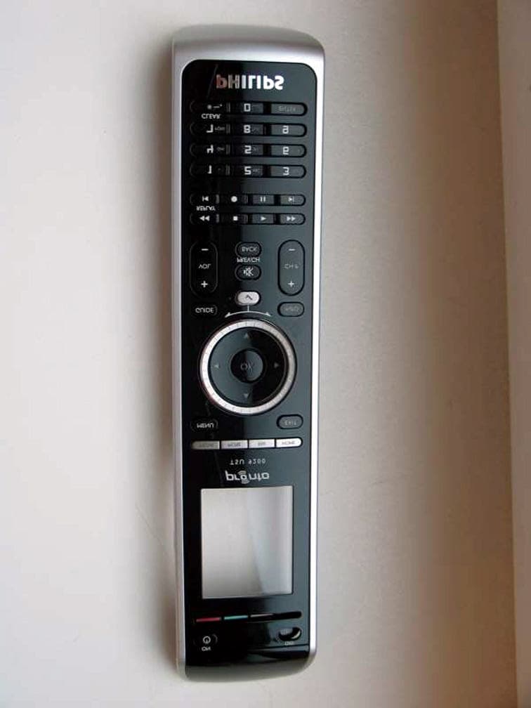
PT5TSU9200
Nov 11, 2007Wireless Remote Control
Equipment Class
DTS - Digital Transmission System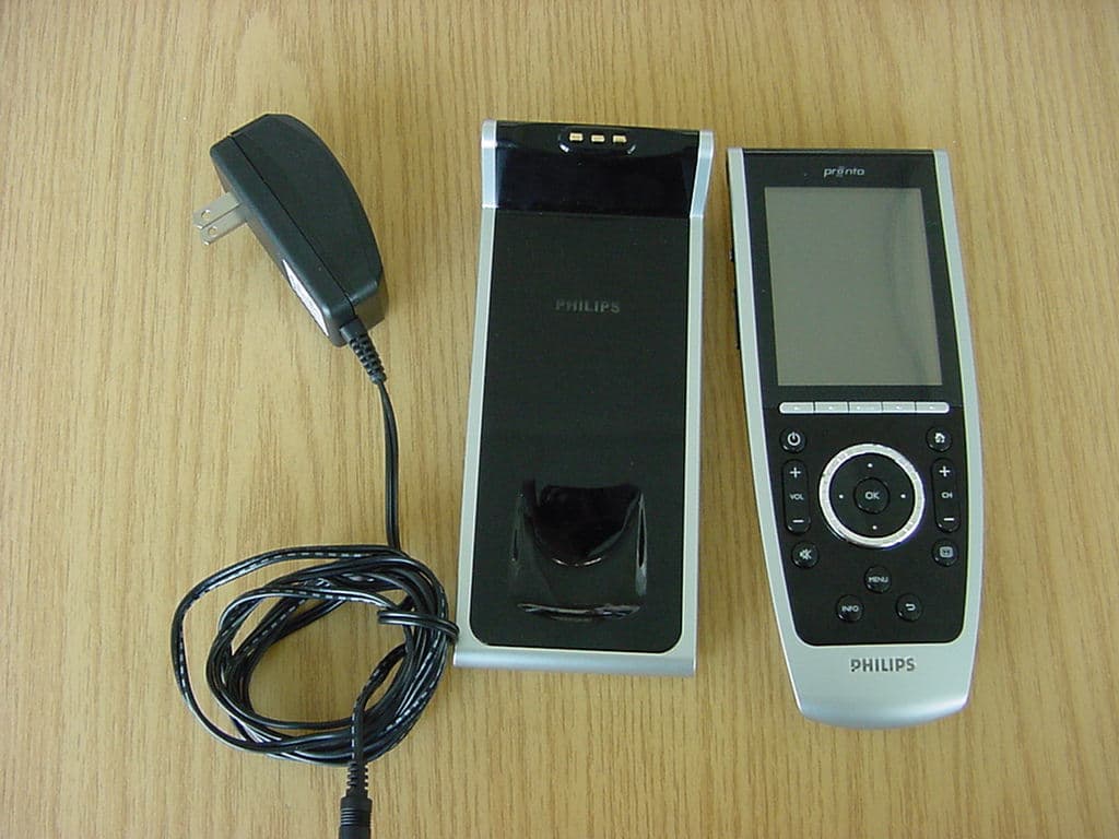
PT5TSU9400
Jul 09, 2007WLAN Remote Control
Equipment Class
DTS - Digital Transmission System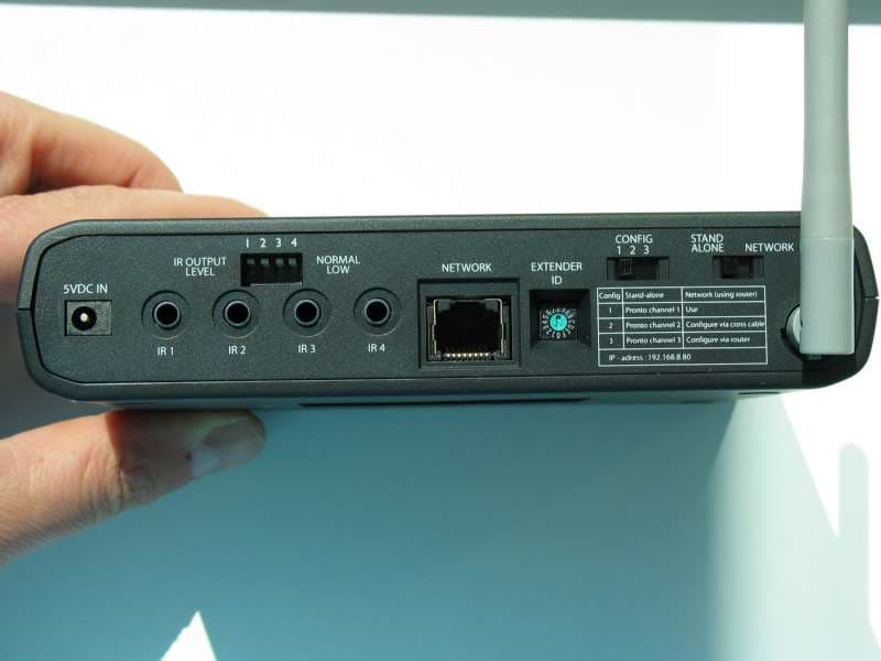
PT5RFX9400
Sep 27, 2006WLAN Transmitter
Equipment Class
DTS - Digital Transmission System
PT5TSU9600
Sep 21, 2006WLAN Remote Control
Equipment Class
DTS - Digital Transmission System
PT5TSU3500
Nov 29, 2005Entertainment device Remote Control
Equipment Class
DSC - Part 15 Security/Remote Control Transmitter