PT5RFX9400WLAN Transmitter
Philips Consumer Lifestyle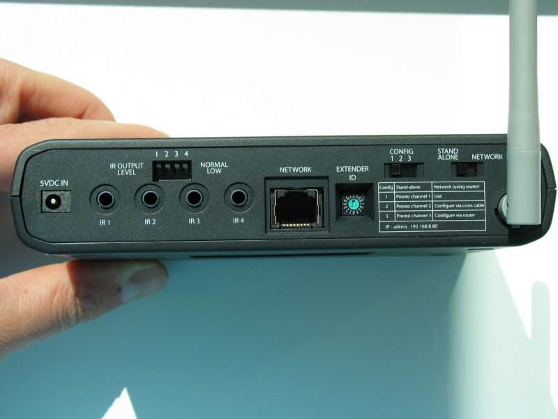
Click to zoom
Application Details
- Equipment Class
- DTS - Digital Transmission System
- Date of Grant
- Sep 27, 2006
- Application Purpose
- Original Equipment
- Date of Application
- Sep 27, 2006
- Equipment Note
- WLAN Transmitter
- Frequency Range
- 2412.00000000 - 2462.00000000
- Company
- Philips Consumer Lifestyle
- Country
- Belgium
Documents & Files
Document Text
Text extracted from the exhibit documents filed with the FCC. Open a document above to read the original.
Users Manual
coverA coverB ENGLISH RFX9400 Starter’s Guide ESPAÑOL FRANÇAIS Starter’s Guide Manual de inicio Guide de démarrage RFX9400 1 RFX9400 Starter’s Guide RFX9400 Starter’s Guide Contents Before You Start..............................................2 Unpacking the Extender ...................................3 Configuring the Extender ..................................4 Stand-alone Connection ...............................4 Network Connection ....................................4 Installing the Pronto Wireless Extender ..............7 Connecting the Extender to AV-equipment .........7 Support..........................................................7 Troubleshooting ..........................................7 Firmware Update ........................................9 Specifications ...............................................10 IFU Approbation / Safety Content RFX9400 ...........i FCC Compliancy ..........................................i Regulations According to R&TTE .....................ii Stand-alone Mode Network Mode ENGLISH 2 RFX9400 Starter’s GuideRFX9400 Starter’s Guide Before You Start The Pronto Wireless Extender is an important element of the Pronto System and makes it possible to control AV-equipment via RF in the entire house. In order to use the Extender in a wireless Pronto Network: •Configurethe Extender: connect it to the PC and use the Configuration Tool. •Installthe Extender: connect it to external AV-equipment, like a TV or receiver. The Extender can be used in two ways: Stand-alone Mode This is the so-called ‘Ad-Hoc Mode’: a router is not required. Stand-alone Advantages: •The Extender is easily configured and installed. •It operates independently from other networks and network settings. Refer to the chapter ‘Stand-alone Connection’on page 5 to configure the Extender in Stand-alone Mode. NoteIf you want to use the Escient Fireball audio server in combination with one or more Extenders, the Extenders have to be configured in Network Mode. Network Mode This is the so-called ‘Infrastructure Mode’: the Extender is used in a network with a router. Network Advantages: •A network allows the use of repeaters, which enlarges the range of the Pronto System. •When using a dedicated Pronto Network, the Extender can operate independently from settings in other networks. •The Extender in Network Mode can be given a fixed IP address, which increases reliability. •The network connection can be encrypted. Refer to the chapter ‘Network Connection’on page 5 to configure the Extender in Network Mode. NoteAn Extender that has been configured in Stand-alone Mode can always be reconfigured for use in Network Mode and vice versa. You can use up to 16 different Extenders in the same Pronto Network. 3 RFX9400 Starter’s Guide Unpacking the Extender Pronto Wireless Extender Front Panel Antenna Configuration switch •In Stand-aloneMode: changes the RF channel. •In NetworkMode: indicates the connection type. Power input 4 IR outputs 4 dipswitches for the IR outputs Back Panel Extender ID switchEthernet input (RJ45) Stand-alone/ Network switch 2 Dual IR Emitters 2 Mini-jack IR Cables Power AdapterConfiguration Cable Crossed Ethernet cable WiFi LED Ethernet LED Busy LED Power LED ENGLISH 4 RFX9400 Starter’s Guide Configuring the Extender NoteBefore you start configuring the Extender, check if there are any firmware updates available in the Downloads section on www.pronto.philips.com. Refer to the chapter ‘Firmware Update’ on page 9 for further details. Stand-alone Connection To configure the Stand-alone Extender: 1Plug in the Extender’s power adapter. The Extender will start up. When start-up has finished, the Power and WiFi LEDs are green. 2 Use the default switchsettings of the Extender: Note•If there is already an Extender with ID 0, set the Extender ID switch to an ID that is not used yet. •If there is any interference with other products in or around the house, the Configuration switch can be set to a different RF channel. •Make sure the same Extender ID and RF channel are used on the Extender and the Pronto Control Panel. 3 Configure the Control Panel’s configuration fileso that the Control Panel can work with the Extender. For more details, refer to the ProntoEdit Professional Online Help. Network Connection In the case of a network connection, the Extender is made part of the wireless Pronto Network. There are two ways to use the Extender in a network: •Wiredconnection •Wirelessconnection Stand-alone/NetworkStand-alone Configuration switch1 Extender ID0 Extender Router Wireless Access Point Straight Ethernet Cable Extender Wireless Access Point Control Panel Control Panel 5 RFX9400 Starter’s Guide To configure the Network Extender: 1Connect the Extender to the PC with the configuration cable(this is the crossed Ethernet cable enclosed). 2Set the switchescorrectly: Note•If there is already an Extender with ID 0, set the Extender ID switch to an ID that is not used yet. •Make sure the same Extender ID is used on the Extender and the Pronto Control Panel. 3Plug in the Extender’s power adapter. The Extender will start up. After startup, the Power and Ethernet LEDs are green and the Busy LED is red/green blinking. 4Open the browser. 5Type the IP address of the Extender (printed on the bottom of the Extender) in the address bar of the browser. The Configuration Toolopens in the browser. 6Follow the onscreen instructions and make sure you have the following information at hand: •If the Extender will be connected wirelessly to the Pronto Network: the SSIDand encryption settings. •If the Extender will be operating with a fixed IP address: the IP address, netmaskand default gateway. TipTo ensure optimal performance, use a dedicated network for all Pronto communication. This makes the Pronto Network independent from other network traffic and changes in network settings. 7Disconnectthe Extender from the PC. 8Connect the Extender to the Pronto Network: •For a wiredconnection, connect the Extender to the ro…
Text truncated - open the document above for the full version.
Cover Letter(s)
September 14, 2006 CONFIDENTIALITY REQUEST Federal Communications Commission Authorization and Evaluation Division 7435 Oakland Mills Road Columbia, MD 21046 Re: Philips Industrial Activities submittal for Spread Spectrum System, FCC ID: PT5RFX9400 Gentlemen: Philips Industrial Activities, herein submits an Application for Equipment Authorization for certification of a digital transmitter under FCC Rules Part 15. Philips Innovative Applicatins requests, pursuant to 47CFR 0.459, post grant confidentiality for portions of the material contained in this application such that the identified material will be withheld from public inspection following the grant of this authorization. This material, as indicated by request for confidentiality of the item during the electronic submission process and further identified below, includes: 1. Circuit diagrams submitted as attachment: "schematics”. 2. Block diagram submitted as attachment “block diagram”. 3. Theory of operation submitted as attachment “operational description”. Specifically, these exhibits contain information relating to circuit function and complexity that could be of benefit to competitors. The material contains trade secrets and confidential information that Philips does not customarily release to the public and which is otherwise not generally available to the public. Please contact the undersigned by phone at 410-531-3439, by fax at 410-531-0807, by email at [email protected], or by correspondence at the address below if there are any further questions or additional information needed concerning this filing. Regards, (signed) Phillip Inglis, TRP/Cetracoms 14085 Howard Rd. Dayton, MD. 21036
ID Label/Location Info
3104 200 0714 Approbation sticker RFX9400 CLASS NO SCALE SCHAAL PROJ EUROP GENERAL ROUGHNESS ALGEMENE RUWHEID UNIT EENH. mm ITEM POST ASSEMBLY NO. SAMENSTELLINGSNR. QUANT. AANTAL NAME NAAM CHECK CONTR. DAT. SUPERS. VERV. Property of Eigendom van N.V. PHILIPS GLOEILAMPENFABRIEKEN EINDHOVEN - NEDERLAND 2822 100 02501 TOLERANCES UNLESS OTHERWISE STATED TOLERANTIES TENZIJ ANDERS VERMELD DIMENSION MAAT ANGLE HOEK MA TERIAL MA TERIAAL TREA TMENT BEHANDELING . . . . . . UN-D 28 . . R a in um , A A UN-D 603 PATTERN NO./MODELNR. ORDER NO./ORDERNR. QUANT. AANTAL PHILIPS RFX9400 Frans Michiels PL2006-03-09 01 110 0110 2 2006-05-22 ENVIRONMENTAL REQUIREMENT : NO BANNED SUBSTANCES ACC. TO UAW-0480/100 A4 ALL RIGHTS ARE RESER VED, REPRODUCTION IN WHOLE OR IN P AR T IS PROHIBITED WITHOUT THE WRITTEN CONSENT OF THE COPYRIGHT OWNER. R2 +/-0.2 Thickness inclusive adhesive = 0,4 max Front side Punching direction Rear side self adhesive < Outline artwork version to use for printing on the product. 3104-200-0714-2-110 (2006-05-15).eps Polypropylene Axprint Fine Sand. Thickness 0.3 mm. 6NE100 PRINTING REQUIREMENTS - Frontside : no printing - Rearside : acc. to UAN-D1235 : App30 - Clim1 -ADHESIVE REQUIREMENTS - Rearside has to be self adhesive and adhesive and protected with an easely removable layer - Adhesive specification equivalent to Mactac-Macband B1148 GENERAL REQUIREMENTS - PCB and PCT free acc. to UAN-D1675 - Cadmium free acc. to UAN-D1597 - Product must be free from scratches and damages PRINTING - Print on back side acc. to OUTLINE ARTWORK version on this drawing. color text : White color background : Pantone E327-2 Dark gray Color of rectangular area: No printing, it will be transparent. 2005-07-19 2004-06-01 2006-03-03 Transparent area ! 2004-07-13 2004-08-04 30 +0,1 -0,2 60 +0,1 -0,2 +/-0.2 DELIVER - Approbation sticker to be delevered on sheet Dimensions and Prin ting changed .2 R F X 9400 5 V ____ _ _ _ 2A MADE IN B E L G IU M 30 +0,1 -0,2 60 +0,1 -0,2 P hilips C ons umer E lec tronic s C ompa ny , Ma rietta , G A 30006-0026 U . S . A . 17 33 This Class B digital apparatus complies with Canadian ICES-003. Cet appareil numerique de la classe B est conforme a la norme NMB-003 du Canada. ` ` Z043 FCC ID : PT5RFX9400 IC: 135P-RFX9400 2006-05-22
RF Exposure Info
September 14, 2006 RF Exposure This transmitter has a nominal power output of 0.058 watts. In this application the card is inserted in a hand held banking terminal. Since the unit is only used while at arms length with a communications interval that is very short (sufficient to transfer credit card info only) the Commission considers the application to be mobile device. Information is provided to the user that he should operate the unit only at arm’s length. Compliance with the RF exposure limit for a distance of 20 cm (mobile device classification) for a power output of 53 mW EIRP can be calculated according to Pd = P/4piR 2 or 115/4x3.14x400 = 0.01 mW/cm 2 . This is below the FCC compliance limit. Phillip Inglis Consultant to Philips
Test Report
Reviewed by: FCC ID: PT5RFX9400 FCC Pt. 15.247 CERTIFICATION TEST REPORT (WLAN 802.11b/g) Quality Manager Test Report S/N: Test Dates: EUT Type: 0609140801 September 15 - 18, 2006 Pronto Wireless Extender Page 1 of 35 © 2006 PCTEST Engineering Laboratory, Inc. Ver. 2.61 Applicant Name: Date of Testing: Philips Industrial Activities Louvain September 15 - 18, 2006 Interleuvenlaan 74-82 Test Site/Location: 3001, Leuven PCTEST Lab, Columbia, MD, USA Belgium Test Report Serial No.: 0609140801 FCC ID: PT5RFX9400 APPLICANT: Philips Industrial Activities Louvain Model(s): RFX9400 EUT Type: Pronto Wireless Extender Max. RF Output Power: 17.67 dBm Conducted (b) 17.31 dBm Conducted (g) Frequency Range: 2412 - 2462 MHz (DSSS/OFDM) FCC Classification: Digital Transmission System (DTS) FCC Rule Part(s): Part 15.247 Test Device Serial No.: N/A This equipment has been shown to be capable of compliance with the applicable technical standards as indicated in the measurement report and was tested in accordance with the measurement procedures specified in ANSI C-63.4-2003. I attest to the accuracy of data. All measurements reported herein were performed by me or were made under my supervision and are correct to the best of my knowledge and belief. I assume full responsibility for the completeness of these measurements and vouch for the qualifications of all persons taking them. Grant Conditions: Listed output power is conducted. PCTEST certifies that no party to this application has been denied the FCC benefits pursuant to Section 5301 of the Anti-Drug Abuse Act of 1988, 21 U.S.C. 862. PCTEST ENGINEERING LABORATORY, INC. 6660-B Dobbin Road, Columbia, MD 21045 USA Tel. 410.290.6652 / Fax 410.290.6554 http://www.pctestlab.com CERTIFICATE OF COMPLIANCE FCC PART 15.247 Certification Reviewed by: FCC ID: PT5RFX9400 FCC Pt. 15.247 CERTIFICATION TEST REPORT (WLAN 802.11b/g) Quality Manager Test Report S/N: Test Dates: EUT Type: 0609140801 September 15 - 18, 2006 Pronto Wireless Extender Page 2 of 35 © 2006 PCTEST Engineering Laboratory, Inc. Ver. 2.61 TABLE OF CONTENTS FCC PART 15.247 MEASUREMENT REPORT...................................................................................................3 1.0 INTRODUCTION ..................................................................................................................................................... 4 1.1 EVALUATION PROCEDURE ............................................................................................................................................... 4 1.2 SCOPE ................................................................................................................................................................................. 4 1.3 PCTEST TEST LOCATION .................................................................................................................................................. 4 2.0 PRODUCT INFORMATION ..................................................................................................................................... 5 2.1 EQUIPMENT DESCRIPTION ............................................................................................................................................... 5 2.2 EMI SUPPRESSION DEVICE(S)/MODIFICATIONS............................................................................................................ 5 3.0 DESCRIPTION OF TEST ........................................................................................................................................ 6 3.1 CONDUCTED EMISSIONS .................................................................................................................................................. 6 3.2 RADIATED EMISSIONS ....................................................................................................................................................... 7 4.0 ANTENNA REQUIREMENTS.................................................................................................................................. 8 5.0 TEST EQUIPMENT CALIBRATION DATA .............................................................................................................. 9 6.0 TEST RESULTS .................................................................................................................................................... 10 6.1 6DB BANDWIDTH MEASUREMENT – 802.11B/G ............................................................................................................ 11 6.2 OUTPUT POWER MEASUREMENT – 802.11B ................................................................................................................ 15 6.3 OUTPUT POWER MEASUREMENT – 802.11G................................................................................................................ 16 6.4 POWER SPECTRAL DENSITY (802.11B/G) ..................................................................................................................... 17 6.5 OUT OF BAND EMISSIONS (BAND EDGE)...................................................................................................................... 21 6.6 RADIATED MEASUREMENTS .......................................................................................................................................... 23 6.7 RADIATED RESTRICTED BAND MEASUREMENTS ....................................................................................................... 27 6.8 LINE-CONDUCTED TEST DATA ....................................................................................................................................... 28 6.9 RECEIVER SPURIOUS MEASUREMENTS ...................................................................................................................... 30 7.0 CONCLUSION ....................................................................................................................................................... 31 EXHIBIT A – L…
Text truncated - open the document above for the full version.
Contact Information
Applicant
Luuk Bartelet(Approbation, Safety and Regulatory Affairs Manager)
Technical Contact
PCTEST Engineering Laboratory, Inc.Randy Ortanez
[email protected]410-290-6652
6660-B Dobbin Road · Columbia, Maryland · United States
Test Firm
PCTEST Engineering Laboratory, Inc.Randy Ortanez
Technical Specifications
| # | Rule Parts | Frequency Range | Power Output |
|---|---|---|---|
| 1 | 15C | 2.41 GHz - 2.46 GHz | 59.00 mW |
Other Applications from Philips Consumer Lifestyle
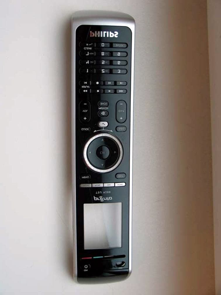
PT5TSU9200
Nov 11, 2007Wireless Remote Control
Equipment Class
DTS - Digital Transmission System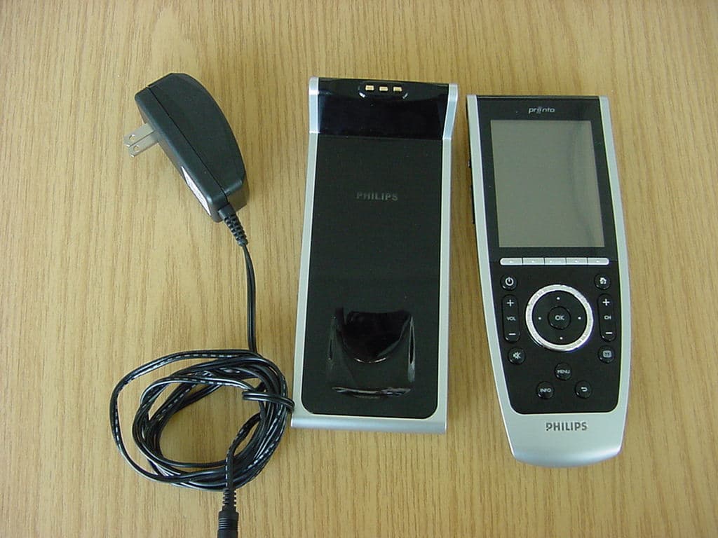
PT5TSU9400
Jul 09, 2007WLAN Remote Control
Equipment Class
DTS - Digital Transmission System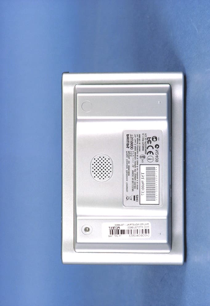
PT5TSU9600
Sep 21, 2006WLAN Remote Control
Equipment Class
DTS - Digital Transmission System
PT5TSU3500
Nov 29, 2005Entertainment device Remote Control
Equipment Class
DSC - Part 15 Security/Remote Control Transmitter
PT5RC9800I
Aug 10, 2004Entertainment System Remote Control
Equipment Class
DTS - Digital Transmission System