PT5RC5400Touch Screen Remote Control
Philips Consumer Lifestyle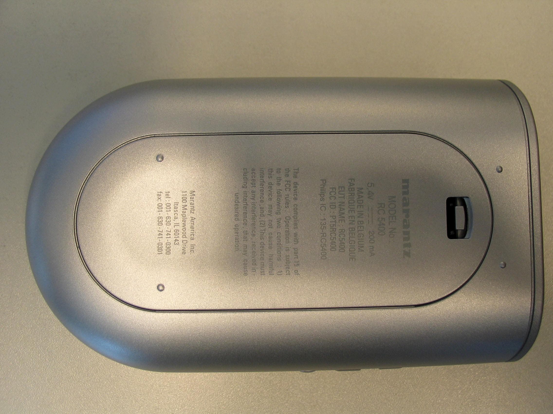
Click to zoom
Application Details
- Equipment Class
- DSC - Part 15 Security/Remote Control Transmitter
- Date of Grant
- Aug 13, 2003
- Application Purpose
- Original Equipment
- Date of Application
- Aug 13, 2003
- Equipment Note
- Touch Screen Remote Control
- Frequency Range
- 418.00000000 - 418.00000000
- Company
- Philips Consumer Lifestyle
- Country
- Belgium
Documents & Files
Document Text
Text extracted from the exhibit documents filed with the FCC. Open a document above to read the original.
Users Manual
Rhein Tech Laboratories Client: Philips RCS 360 Herndon Parkway Suite 1400 Model: RC5400 FCC ID: PT5RC5400 Herndon, VA 20170 Standards: FCC Part 15.231 http://www.rheintech.com RTL WO# : 2003133 Page 29 of 49 APPENDIX G: MANUAL Please see the following pages. Model RC5400 User Guide Touch Screen Remote Control Automating Your Home Theater With The Marantz RC5400 RC5400 Remote Control User Guide The information in this manual is copyright-protected. No part of this user guide may be copied or reproduced in any form without prior written consent from Marantz. MARANTZ SHALLNOTBE LIABLE FOR OMISSIONS OR FOR TECHNICALOR EDITO- RIALERRORS CONTAINED IN THIS USER GUIDE. MARANTZ SHALLNOTBE HELD LIABLE FOR INCIDENTALOR CONSEQUENTIALDAMAGES RESULTING FROM THE SUPPLYING OR USE OF THIS INFORMATION. MARANTZ SHALLNOTBE HELD LIA- BLE FOR INCIDENTALOR CONSEQUENTIALDAMAGES RESULTING FROM THE PERFORMANCE OR USE OF THE MATERIALS DESCRIBED IN THIS USER GUIDE. The information in this user guide may be subject to change without prior notice. All other brand or product names are trademarks or registered trademarks of their respec- tive companies or organizations. FCC Compliancy: This equipment has been tested and found to comply with the limits for a Class B digital device, pursuant to part 15 of the FCC rule. These limits are designed to provide reasonable protection against harmful interference in residential installation. This equipment generates, uses, and can radiate radio frequency energy and , if not installed and used in accordance with the instructions, may cause harmful interference to radio communications. However, there is not guarantee that interference will not occur in a particular installation. If this equipment does cause harmful inter- ference to radio or television reception, which can be determined by turning the equipment off and on, the user is encouraged to try to correct the interference by one or more of the following measures: nReorient or relocate the receiving antenna. nIncrease the separation between the equipment and receiver. nConnect the equipment into an outlet on a different circuit from the receiver. nConsult the dealer or an experienced radio/TV technician for help. CAUTION: The user changes or modifications not expressly approved by the party responsible for compliance could void the user’s authority to operate the equipment. For Europe User Guide 1 Introduction2 1. The Marantz RC5400 2 2. The Battery 3 Getting Started6 1. Activating the RC5400 6 2. Navigating the RC5400 7 3. Operating a Device 11 4. Check Battery Life - The Information Page 12 5 The Setup Pages12 6. The Mode Menus 14 7. Adjusting the Touch Screen Contrast14 Customizing Your RC540016 1. Introduction 16 2. Cloning All Your Existing Remotes 16 3 Complex Operation? Macros or Help... 18 4. Programming Help Lists 20 5. Macro Capabilities 21 6. Programming Macros 23 Reference26 1. Learning IR Commands 26 2. Labeling Buttons, Pages and Devices 30 3. Adding Devices33 4. Deleting Buttons and Devices 37 5. Moving Devices39 6. Programming Macros 40 7. Using the Remote Control with RF (Radio Frequency) 44 8. Wizz.it Software 46 Maintaining the RC540048 Troubleshooting49 Frequently Asked Questions52 Overview of Symbols54 Specifications56 Index57 Service and Support62 Table of Contents User Guide 2 The RC5400 is designed to control most devices that understand infra- red (IR) remote control signals. Its easy-to-use Touch Screen and its intuitive interface make it a perfect remote control for every user. The RC5400 is completely customizable and programmable. You can add devices and functions, re-label buttons, record macros and animate your macros. Although the RC5400 is pre-programmed for Marantz components, a vast collection of built-in tab guided panels with pre- arranged button art enables you to easily choose the perfect interface for any non-Marantz component. The RC5400 easily “learns”com- mands from the vast majority of manufacturers’remote controls. Introduction VOLUME Up/Down CHANNELUp/Down MUTE buttons (page 11) Infrared (IR) Eyes(page 26) Right Function button (page 8) 4-Way Cursor navigation buttons (page 11) Page +/ - buttons (page 10) Backlight button(page 6) USBPort (page 47) HOME button (page 7) 1. The Marantz RC5400 Touch Screen Left Function button (page 8) MENU button (page 11) ENTER button (page 11) EXIT button (page 11) The Touch Screen When you use the RC5400 for the first time, you will have to: •Install the battery pack. •Place the RC5400 in the docking station and charge the RC5400. •Tap the INFObutton on the Upper System Area to check battery life. Warning:Use the docking station only with supplied NiMH rechargeable battery pack. We strongly advise you NOTto plug other appliances (like mobile phones, PDA’s) into the docking station. This will damage both the connector and the appliance. User Guide 3 Introduction MODE icon (page 7) INFO button(page 3) DEVICE SCROLL button (page 9) DEVICE OVERVIEW button (page 8) UPPER TOOLBAR CURSOR NAVIGATION button (page 9) USER CONTROLAREA LOWER TOOLBAR PAGEOVERVIEW button (page 9) 2. The Battery DEVICE SCROLL button (page 9) User Guide 4 Installing the Battery Pack 1 Press the latch on the battery cover and remove the battery cover from the RC5400. 2 Place the battery pack in the battery compartment. 3 Plug the cable of the battery pack in the connector as illustrated. 4 Place the battery cover back on. NoteMake sure the cable of the battery pack does not get stuck between the molded interior and the battery cover. After a few seconds, the RC5400 starts up automatically and an Introduction screen appears. The RC5400 beeps twice to indicate that it has finished starting up. Because the battery pack of the RC5400 is not fully pre- charged, you will have to charge it as described in the next page. Introduction Charging the RC5400 For charging the RC5400, you use the docking station. 1 Connect the power adapter to the docking station and plug it into a wall outle…
Text truncated - open the document above for the full version.
Cover Letter(s)
Rhein Tech Laboratories Client: Philips RCS 360 Herndon Parkway Suite 1400 Model: RC5400 FCC ID: PT5RC5400 Herndon, VA 20170 Standards: FCC Part 15.231 http://www.rheintech.com RTL WO# : 2003133 Page 23 of 49 APPENDIX B: CONFIDENTIALITY REQUEST LETTER Please see the following page.
Cover Letter(s)
Rhein Tech Laboratories Client: Philips RCS 360 Herndon Parkway Suite 1400 Model: RC5400 FCC ID: PT5RC5400 Herndon, VA 20170 Standards: FCC Part 15.231 http://www.rheintech.com RTL WO# : 2003133 Page 22 of 49 APPENDIX A: AGENCY AUTHORIZATION LETTER Please see the following page. Philips Innovative Applications NV Interleuvenlaan 74-82, B-3001 Leuven, Belgium BCT Remote Control Systems 2003 Jul 23 to: American TCB,Inc. 6731 Whittier Avenue Suite C110 Mc Lean, VA 22101 To Whom It May Concern: Please be advised that Philips Innovative Applications hereby authorizes Rhein Tech Laboratories,Inc,360 Herndon Parkway, Suite 1400, Herndon, VA 20170 to act on our behalf, until otherwise notified, for applications submitted to American Telecommunications Certification Body, Inc. (ATCB). We certify that we are not subject to denial of federal benefits, that includes FCC benefits, pursuant to Section 5301 of the Anti-Drug Abuse Act of 1988, U.S.C. 862. Further, no party, as defined in 47 CFR 1.2002(b), to the application is subject to denial of federal benefits, that includes FCC benefits. Thank you for your attention to this matter. Heysse Gert Approbation Manager & Safety officer
Cover Letter(s)
American Telecommunications Certification Body Inc. 6731 Whittier Ave, McLean, VA 22101 August 10, 2003 RE: FCC ID: PT5RC5400_ATCB000664 Attention: Kathy Grzovic / Rick McMurray I have a few comments on this Application. 1. The theory of operation states that,” the user has the possibility to upgrade the database and/or software in the device.” Please verify that the software is not capable of affecting the transmitter frequency or power ratings. - 2. Since the device is also a computer peripheral device, has the proper DoC or certification been done? Please provide evidence of the DoC. - 3. Please note that 2.1033(a)(6) states that, “The report shall include sample calculations showing how the measurement results were converted for comparison with the technical requirements.” While there is information on the duty cycle calculations, there does not appear to be sample calculations for the radiated or conducted measurements. Please provide or please show where in the report these sample calculations are located. - Dennis Ward mailto:[email protected] The items indicated above must be submitted before processing can continue on the above referenced application. Failure to provide the requested information may result in application termination. Correspondence should be considered part of the permanent submission and may be viewed from the Internet after a Grant of Equipment Authorization is issued. Please do not respond to this correspondence using the email reply button. In order for your response to be processed expeditiously, you must submit your documents through the AmericanTCB.com website. Also, please note that partial responses increase processing time and should not be submitted. Any questions about the content of this correspondence should be directed to the sender.
Cover Letter(s)
American Telecommunications Certification Body Inc. 6731 Whittier Ave, McLean, VA 22101 August 10, 2003 RE: FCC ID: PT5RC5400_ATCB000664 Attention: Kathy Grzovic / Rick McMurray I have a few comments on this Application. 1. The theory of operation states that,” the user has the possibility to upgrade the database and/or software in the device.” Please verify that the software is not capable of affecting the transmitter frequency or power ratings. Response : Per Philips RCS Leuven: The software is not capable of affecting the frequency or the power of the RF transmitter in anyway. The user can only turn on or off the feature; the frequency and power are hardware controlled. 2. Since the device is also a computer peripheral device, has the proper DoC or certification been done? Please provide evidence of the DoC. Response : Please see the DoC report uploaded with this response. 3. Please note that 2.1033(a)(6) states that, “The report shall include sample calculations showing how the measurement results were converted for comparison with the technical requirements.” While there is information on the duty cycle calculations, there does not appear to be sample calculations for the radiated or conducted measurements. Please provide or please show where in the report these sample calculations are located. Response : Please see section 7 in the revised report that was uploaded with this response. Dennis Ward mailto:[email protected] The items indicated above must be submitted before processing can continue on the above referenced application. Failure to provide the requested information may result in application termination. Correspondence should be considered part of the permanent submission and may be viewed from the Internet after a Grant of Equipment Authorization is issued. Please do not respond to this correspondence using the email reply button. In order for your response to be processed expeditiously, you must submit your documents through the AmericanTCB.com website. Also, please note that partial responses increase processing time and should not be submitted. Any questions about the content of this correspondence should be directed to the sender.
External Photos
Rhein Tech Laboratories Client: Philips RCS 360 Herndon Parkway Suite 1400 Model: RC5400 FCC ID: PT5RC5400 Herndon, VA 20170 Standards: FCC Part 15.231 http://www.rheintech.com RTL WO# : 2003133 Page 34 of 49 APPENDIX I: EXTERNAL PHOTOGRAPHS PHOTOGRAPH 7: TOUCH SCREEN REMOTE CONTROL IN DOCKING STATION Rhein Tech Laboratories Client: Philips RCS 360 Herndon Parkway Suite 1400 Model: RC5400 FCC ID: PT5RC5400 Herndon, VA 20170 Standards: FCC Part 15.231 http://www.rheintech.com RTL WO# : 2003133 Page 35 of 49 PHOTOGRAPH 8: FRONT VIEW OF TOUCH SCREEN REMOTE CONTROL Rhein Tech Laboratories Client: Philips RCS 360 Herndon Parkway Suite 1400 Model: RC5400 FCC ID: PT5RC5400 Herndon, VA 20170 Standards: FCC Part 15.231 http://www.rheintech.com RTL WO# : 2003133 Page 36 of 49 PHOTOGRAPH 9: REAR VIEW OF TOUCH SCREEN REMOTE CONTROL Rhein Tech Laboratories Client: Philips RCS 360 Herndon Parkway Suite 1400 Model: RC5400 FCC ID: PT5RC5400 Herndon, VA 20170 Standards: FCC Part 15.231 http://www.rheintech.com RTL WO# : 2003133 Page 37 of 49 PHOTOGRAPH 10: LEFT SIDE VIEW OF TOUCH SCREEN REMOTE Rhein Tech Laboratories Client: Philips RCS 360 Herndon Parkway Suite 1400 Model: RC5400 FCC ID: PT5RC5400 Herndon, VA 20170 Standards: FCC Part 15.231 http://www.rheintech.com RTL WO# : 2003133 Page 38 of 49 PHOTOGRAPH 11: RIGHT SIDE VIEW OF TOUCH SCREEN REMOTE Rhein Tech Laboratories Client: Philips RCS 360 Herndon Parkway Suite 1400 Model: RC5400 FCC ID: PT5RC5400 Herndon, VA 20170 Standards: FCC Part 15.231 http://www.rheintech.com RTL WO# : 2003133 Page 39 of 49 PHOTOGRAPH 12: USB CONNECTOR Rhein Tech Laboratories Client: Philips RCS 360 Herndon Parkway Suite 1400 Model: RC5400 FCC ID: PT5RC5400 Herndon, VA 20170 Standards: FCC Part 15.231 http://www.rheintech.com RTL WO# : 2003133 Page 40 of 49 PHOTOGRAPH 13: IR WINDOW VIEW Rhein Tech Laboratories Client: Philips RCS 360 Herndon Parkway Suite 1400 Model: RC5400 FCC ID: PT5RC5400 Herndon, VA 20170 Standards: FCC Part 15.231 http://www.rheintech.com RTL WO# : 2003133 Page 41 of 49 PHOTOGRAPH 14: TOP VIEW OF DOCKING STATION Rhein Tech Laboratories Client: Philips RCS 360 Herndon Parkway Suite 1400 Model: RC5400 FCC ID: PT5RC5400 Herndon, VA 20170 Standards: FCC Part 15.231 http://www.rheintech.com RTL WO# : 2003133 Page 42 of 49 PHOTOGRAPH 15: BOTTOM VIEW OF DOCKING STATION Rhein Tech Laboratories Client: Philips RCS 360 Herndon Parkway Suite 1400 Model: RC5400 FCC ID: PT5RC5400 Herndon, VA 20170 Standards: FCC Part 15.231 http://www.rheintech.com RTL WO# : 2003133 Page 43 of 49 PHOTOGRAPH 16: AC ADAPTER
ID Label/Location Info
Rhein Tech Laboratories Client: Philips RCS 360 Herndon Parkway Suite 1400 Model: RC5400 FCC ID: PT5RC5400 Herndon, VA 20170 Standards: FCC Part 15.231 http://www.rheintech.com RTL WO# : 2003133 Page 25 of 49 APPENDIX D: LABEL AND LABEL LOCATION PHOTOGRAPH 1: FCC ID LABEL LOCATION ON BOTTOM OF TOUCH SCREEN REMOTE CONTROL Rhein Tech Laboratories Client: Philips RCS 360 Herndon Parkway Suite 1400 Model: RC5400 FCC ID: PT5RC5400 Herndon, VA 20170 Standards: FCC Part 15.231 http://www.rheintech.com RTL WO# : 2003133 Page 26 of 49 PHOTOGRAPH 2: FCC ID LABEL LOCATION ON BOTTOM OF DOCKING STATION Please refer to the following page for a sample of the FCC ID label. FCC ID LABEL LOCATION
Internal Photos
Rhein Tech Laboratories Client: Philips RCS 360 Herndon Parkway Suite 1400 Model: RC5400 FCC ID: PT5RC5400 Herndon, VA 20170 Standards: FCC Part 15.231 http://www.rheintech.com RTL WO# : 2003133 Page 44 of 49 APPENDIX J: INTERNAL PHOTOGRAPHS PHOTOGRAPH 17: REAR VIEW OF TOUCH SCREEN REMOTE CONTROL WITH BATTERY COVER REMOVED Rhein Tech Laboratories Client: Philips RCS 360 Herndon Parkway Suite 1400 Model: RC5400 FCC ID: PT5RC5400 Herndon, VA 20170 Standards: FCC Part 15.231 http://www.rheintech.com RTL WO# : 2003133 Page 45 of 49 PHOTOGRAPH 18: REAR VIEW OF TOUCH SCREEN REMOTE CONTROL WITH BATTERY REMOVED Rhein Tech Laboratories Client: Philips RCS 360 Herndon Parkway Suite 1400 Model: RC5400 FCC ID: PT5RC5400 Herndon, VA 20170 Standards: FCC Part 15.231 http://www.rheintech.com RTL WO# : 2003133 Page 46 of 49 PHOTOGRAPH 19: PWB TOP SIDE Rhein Tech Laboratories Client: Philips RCS 360 Herndon Parkway Suite 1400 Model: RC5400 FCC ID: PT5RC5400 Herndon, VA 20170 Standards: FCC Part 15.231 http://www.rheintech.com RTL WO# : 2003133 Page 47 of 49 PHOTOGRAPH 20: PWB BOTTOM SIDE Rhein Tech Laboratories Client: Philips RCS 360 Herndon Parkway Suite 1400 Model: RC5400 FCC ID: PT5RC5400 Herndon, VA 20170 Standards: FCC Part 15.231 http://www.rheintech.com RTL WO# : 2003133 Page 48 of 49 PHOTOGRAPH 21: ANTENNA PART AND MODULE Antenna Rhein Tech Laboratories Client: Philips RCS 360 Herndon Parkway Suite 1400 Model: RC5400 FCC ID: PT5RC5400 Herndon, VA 20170 Standards: FCC Part 15.231 http://www.rheintech.com RTL WO# : 2003133 Page 49 of 49 PHOTOGRAPH 22: PROCESSOR, MEMORY AND LCD DRIVER
Test Report
Engineering and Testing for EMC and Safety Compliance 360 Herndon Parkway, Suite 1400 Herndon, VA 20170 Phone: 703-689-0368; Fax: 703-689-2056; Metro: 703-471-6441 CERTIFICATION APPLICATION REPORT FCC PART 15.231 Test Lab: Rhein Tech Laboratories, Inc. Phone: 703-689-0368 360 Herndon Parkway Fax: 703-689-2056 Suite 1400 Web Site: www.rheintech.com Herndon, VA 20170 E-Mail : [email protected] Applicant: Philips RCS Phone: 32 16 390 850 Contact: Gert Heysse Fax: 32 16 390 800 Interleuvenlaan 74-76 E-Mail: [email protected] 3001 Leuven, Belgium FCC ID: PT5RC5400 GRANTEE FRN NUMBER: 0007771983 PLAT FORM: N/A RTL WORK ORDER NUMBER: 2003133 MODEL(S): RC5400 RTL QUOTE NUMBER: QRTL03-739 DATE OF TEST REPORT: August 11, 2003 American National Standard Institute: ANSI/TIA/EIA603 and ANSI/TIA/EIA 603-1 FCC Classification: DSC; Part 15 Security/Remote Control Transmitter FCC Rule Part(s): Part 15.231 Periodic operation in the band 40.66-40.70 MHz and above 70 MHz Digital Interface Information Digital Interface was found to be compliant Receiver Information Receiver was found to be compliant I, the undersigned, hereby declare that the equipment tested and referenced in this report conforms to the identified standard(s) as described in this test report. No modifications were made to the equipment during testing in order to achieve compliance with these standards. Furthermore, there was no deviation from, additions to, or exclusions from the FCC Part 2, FCC Part 15, ANSI/TIA/EIA 603, and ANSI/TIA/EIA 603-1. Signature: Date: August 11, 2003 Typed/Printed Name: Desmond A. Fraser Position: President Rhein Tech Laboratories Client: Philips RCS 360 Herndon Parkway Suite 1400 Model: RC5400 FCC ID: PT5RC5400 Herndon, VA 20170 Standards: FCC Part 15.231 http://www.rheintech.com RTL WO# : 2003133 Page 2 of 49 TABLE OF CONTENTS 1 GENERAL INFORMATION..........................................................................................................................................................................4 1.1 SCOPE .................................................................................................................................................................................. 4 1.2 TEST FACILITY .................................................................................................................................................................. 4 1.3 RELATED SUBMITTAL(S)/GRANT(S)............................................................................................................................. 4 2 TEST INFORMATION....................................................................................................................................................................................5 2.1 TEST JUSTIFICATION ....................................................................................................................................................... 5 2.2 EXERCISING THE EUT ...................................................................................................................................................... 5 2.3 TEST RESULT SUMMARY ................................................................................................................................................ 5 2.4 TEST SYSTEM DETAILS ................................................................................................................................................... 5 2.5 CONFIGURATION OF TESTED SYSTEM ........................................................................................................................ 7 3 CONDUCTED EMISSIONS...........................................................................................................................................................................8 3.1 TEST METHODOLOGY FOR CONDUCTED EMISSIONS MEASUREMENTS ............................................................ 8 3.2 CONDUCTED EMISSIONS TEST DATA .......................................................................................................................... 9 3.3 TEST EQUIPMENT USED FOR TESTING CONDUCTED EMISSIONS ....................................................................... 10 4 RADIATED EMISSIONS - §15.231............................................................................................................................................................11 4.1 RADIATED EMISSION LIMITS TEST PROCEDURE.................................................................................................... 11 4.2 DUTY CYCLE AND COMPLIANCE WITH 15.231(A)(1) .............................................................................................. 11 4.3 RADIATED EMISSION TEST DATA .............................................................................................................................. 15 4.4 TEST EQUIPMENT USED FOR TESTING RADIATED SPURIOUS EMISSIONS ....................................................... 17 5 MODULATED BANDWIDTH - §15.231(C).............................................................................................................................................18 5.1 MODULATED BANDWIDTH TEST PROCEDURE ....................................................................................................... 18 5.2 MODULATED BANDWIDTH TEST DATA .................................................................................................................... 18 5.3 TEST EQUIPMENT USED FOR TESTING MODULATED BANDWIDTH................................................................... 20 6 ANTENNA REQUIREMENT - §15.203 .................................................................................................................................... 21 7 SAMPLE CALCULATIONS - §2.1033(A)(6)............................................................................................................................ 21 8 CONCLUSION ................................................…
Text truncated - open the document above for the full version.
Test Setup Photos
Rhein Tech Laboratories Client: Philips RCS 360 Herndon Parkway Suite 1400 Model: RC5400 FCC ID: PT5RC5400 Herndon, VA 20170 Standards: FCC Part 15.231 http://www.rheintech.com RTL WO# : 2003133 Page 30 of 49 APPENDIX H: TEST PHOTOGRAPHS PHOTOGRAPH 3: RADIATED EMISSIONS FRONT VIEW Rhein Tech Laboratories Client: Philips RCS 360 Herndon Parkway Suite 1400 Model: RC5400 FCC ID: PT5RC5400 Herndon, VA 20170 Standards: FCC Part 15.231 http://www.rheintech.com RTL WO# : 2003133 Page 31 of 49 PHOTOGRAPH 4: RADIATED EMISSIONS REAR VIEW Rhein Tech Laboratories Client: Philips RCS 360 Herndon Parkway Suite 1400 Model: RC5400 FCC ID: PT5RC5400 Herndon, VA 20170 Standards: FCC Part 15.231 http://www.rheintech.com RTL WO# : 2003133 Page 32 of 49 PHOTOGRAPH 5: CONDUCTED EMISSIONS FRONT VIEW Rhein Tech Laboratories Client: Philips RCS 360 Herndon Parkway Suite 1400 Model: RC5400 FCC ID: PT5RC5400 Herndon, VA 20170 Standards: FCC Part 15.231 http://www.rheintech.com RTL WO# : 2003133 Page 33 of 49 PHOTOGRAPH 6: CONDUCTED EMISSIONS REAR VIEW
Contact Information
Applicant
Luuk Bartelet(Approbation, Safety and Regulatory Affairs Manager)
Technical Contact
Rhein Tech LaboratoriesRick McMurray
[email protected]703-689-0368
360 Herndon Parkway, Suite 1400 · Herndon, Virginia · United States
Test Firm
Rhein Tech Laboratories, Inc.Rick McMurray
Technical Specifications
| # | Rule Parts | Frequency Range | Power Output |
|---|---|---|---|
| 1 | 15.231 | 418 MHz - 418 MHz | - |
Other Applications from Philips Consumer Lifestyle
PT5TSU9200
Nov 11, 2007Wireless Remote Control
Equipment Class
DTS - Digital Transmission System
PT5TSU9400
Jul 09, 2007WLAN Remote Control
Equipment Class
DTS - Digital Transmission System
PT5RFX9400
Sep 27, 2006WLAN Transmitter
Equipment Class
DTS - Digital Transmission System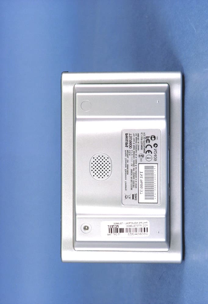
PT5TSU9600
Sep 21, 2006WLAN Remote Control
Equipment Class
DTS - Digital Transmission System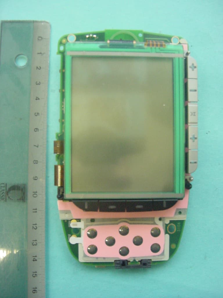
PT5TSU3500
Nov 29, 2005Entertainment device Remote Control
Equipment Class
DSC - Part 15 Security/Remote Control Transmitter