PVQDSCAB002Car Pager
drakesystem co.,ltd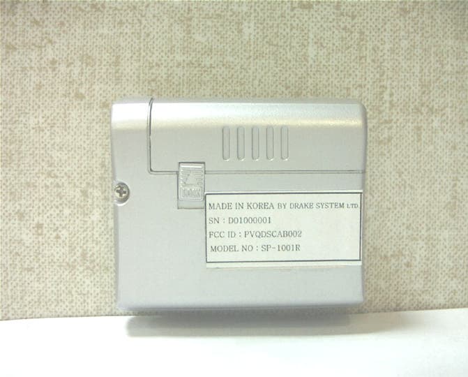
Click to zoom
Application Details
- Equipment Class
- CYY - Communications Receiver used w/Pt 15 Transmitter
- Date of Grant
- Jan 17, 2002
- Application Purpose
- Original Equipment
- Date of Application
- Jan 17, 2002
- Equipment Note
- Car Pager
- Frequency Range
- 433.92000000 - 433.92000000
- Company
- drakesystem co.,ltd
- Country
- South Korea
Documents & Files
Document Text
Text extracted from the exhibit documents filed with the FCC. Open a document above to read the original.
Users Manual
USERS MANUAL SP-1001R Operating Instructions 1.INSTRUCTION MANUAL TABLE OF CONTENTS 1-1. THE USE OF PAGER 1-1-1. LCD DISPLAY OF PAGER 1-1-2. INSERTING BATTERY INTO THE PAGER 1-1-3. FUNCTION OF BUTTON 1-1-4. THE USAGE OF MODE KEY 1-1-5. THE USAGE OF PARKING TIMER 1-1-6. THE EXCHANGE OF BATTERY 1-1-7. RF RECEIVING ON/OFF 1-1-8. HOW TO LEARN ID 1-1-9. THE OPERATION WHEN INSTALLED 1-1-10. ARM DELAY MODE 1-2. THE USE OF PAGER 1-2-1. LCD DISPLAY OF PAGER 13 1 2 3 4 5 6 7 8 9 10 11 12 • ANTENNA • LOW BATTERY INDICATOR • DOOR LOCK • DOOR UNLOCK • ALERT TONE • VIBRATION • RF RECEIVING ON/OFF • CAR SHAPE (WHEN SHOCK-SENSOR IS TRIGGERED, ICON BLINKING) • DOOR OPEN • PARKING ALARM TIMER • WAKE-UP TIMER • CLOCK • TRUNK OPEN 1-2-2. INSERTING BATTERY INTO THE PAGER •A pager turns on all of LCD icons and backlight with alert tone and vibration when the battery (AAA alkaline) is inserted into the pager. •Please remove and re-insert the battery when receiver does not operate like this. •The alert tone is repeated five times, but it is stopped instantly when any button on the receiver is pressed . 1-2-3. FUNCTION OF BUTTON •The right button is MODE KEY which is used for the setting of each function and time. •The left button is PARKING KEY whitch is used for parking timer. 1-2-4. THE USAGE OF MODE KEY •The receiver enters into the change of MODE with beep tone when the MODE KEY is pressed for more then 2 seconds. •The procedure for the change of MODE is as follows. • RF RECEIVING ON/OFF • SELECT OF ALERT TONE or VIBRATION • ADJUST OF CLOCK • WAKE-UP ALARM ON/OFF • ADJUST OF WAKE-UP ALARM TIME •The left button will be used when the change of MODE is required. •When the MODE-KEY is usually pressed shortly, the MODE- KEY is used for the display of previous status or reset of current status. 1-2-5. THE USAGE OF PARKING TIMER •The receiver enters into change of PARKING TIMER with beep tone when the left button is pressed for more then 2 seconds. At that time, the clock on the LCD will blank which enables the change of PARKING TIMER. •At this mode, the left button is used to increase the hour or minute when the icon is blanking and the right button is used to move the blinking icon to the right. •The icon of PARKING TIMER is blanking when the PARKING TIMER is being operated The operation of PARKING TIMER is cancelled when the left button is pressed for more then 2 seconds during the operation of PARKING TIMER. •The previous PARKING TIMER is memorized in the memory of the receiver. You can use the previous PARKING TIMER when you press the left button for more than 2 seconds. 1-2-6. THE EXCHANGE OF BATTERY •Please exchange the current battery with new battery within 2 days when the icon of low battery on the LCD is turned on. •The receiver memorizes the CURRENT MODE, ALARM TIME, PARKING TIME and ID into the memory of the receiver, but it does not memorize the CURRENT TIME. When the battery is exchanged with new battery, you should re-adjust your clock on the receiver. The current time will be set to 12:00 when you change the battery. 1-2-7. RF RECEIVING ON/OFF •The picture of car on the LCD will disappear when the receiver is set to OFF. •The receiver cannot receive a call when the receiver is turned OFF or the ID CODE does not match. 1-2-8. HOW TO LEARN ID •The receiver enters into the ID LEARLING mode when you press two buttons for more then 2 seconds simultaneously and then, it blinks. “Id”on the LCD. The receiver learns the ID and memorizes it if the receiver receives the transmitted signal from tramsmitter within 30 seconds. The transmitted signal from transmitter can be generated when DOOR LOCK, DOOR UNLOCK, TRUNK OPEN, SHOCK SENSOR, DOOR OPEN is sensed. When the receiver succeened in ID learning, the receiver sends triple Short beep. 1-2-9. THE OPERATION WHEN INSTALLED 1-2-9-1. STANT-ALONE OPERATION •The transmitter enters into ARM MODE after 30 seconds when the key is removed from the key box and the transmitter enters into DISARM MODE just after that the car is started by key. MODE PARAMETER OPEERATION OF TRANSMITTER LCD DISPLAY OF RECEIVER ALERT TONE/ VIBRATION DOOR LOCK Instant RF TX ‘LOCK’ICON SINGLE BEEP DOOR UNLOCK Instant RF TX ‘UNLOCK’ICO N DUAL BEEP TRUNK OPEN Instant RF TX & SIREN TRUNK OPEN ALERT TONE (15 TIMES) SHOCK SENSOR Instant RF TX & SIREN BLINKING OF CAR SHAPE ALERT TONE (15 TIMES) ARM MODE DOOR OPEN 30 second wait SIREN/STARTK ILL /RF TX DOOR OPEN ALERT TONE (15 TIMES) DOOR LOCK Instant RF TX ‘LOCK’ICON SINGLE BEEP DISAR M MODE DOOR UNLOCK Instant RF TX ‘UNLOCK’ICO N DUAL BEEP 1-2-9-2. OPERATION INSTALLED WITH CAR ALARM •The transmitter enters into ARM MODE if it receives ARM INPUT from CAR ALARM and enters into DISARM MODE if it does not receive ARM INPUT. MODE PARAMETER OPERATION OF TRANSMITTER LCD DISPLAY OF RECEIVER ALERT TONE/ VIBRATION DOOR LOCK Instant RF TX ‘LOCK’ICON SINGLE BEEP DOOR UNLOCK Instant RF TX ‘UNLOCK’ICO N DUAL BEEP REMOTE START Instant RF TX BLINKING OF WHEEL QUADRUPLE BEEP TRUNK OPEN Instant RF TX & SIREN TRUNK OPEN ALERT TONE (15 TIMES) SHOCK SENSOR Instant RF TX & SIREN BLINKING OF CAR SHAPE ALERT TONE (15 TIMES) ARM MODE DOOR OPEN 30 second wait SIREN/STARTK ILL /RF TX DOOR OPEN ALERT TONE (15 TIMES) DOOR LOCK Instant RF TX ‘LOCK’ICON SINGLE BEEP DOOR UNLOCK Instant RF TX ‘UNLOCK’ICO N DUAL BEEP DISAR M MODE REMOTE START Instant RF TX BLINKING OF WHEEL QUADRUPLE BEEP NOTE : The siren or START-KILL will be stopped instantly when the Transmitter enters into DISARM mode. 1-2-10. ARM DELAY MODE •When the transmitter enters into ARM mode, it has on ARM DELAY mode between DISARM mode and ARM mode. 1-2-10-1. STAND-ALONE OPERATION At the stand-alone operation, the transmitter has a 30 seconds ARM DELAY. The door-open and shock sensor do not operate during ARM DELAY. 1-2-10-2. OPERATION WITH CAR ALARM The transmitter has a 5 seconds ARM DELAY in this operation. The door lock and door unlock will operate during ARM DELAY. 1-3. INSTALLATION OF TRANSMITTER 1).Please connec…
Text truncated - open the document above for the full version.
Block Diagram
SP-1001R BLOCK DIAGRAM 1. 5V to 3V BFQ67 1st MIXER BFQ67 FILTER 1st IF AMP 2nd MIXER (KS8514) SHAPING CIRCUIT 21.4MHz KTC3879Y RX DATA 1st LOCA L 2nd LOCA L FILTER POWER UP CUIRCUIT (RH5RI301B ) 1.5V 3V CPU ( KS57C21208 ) & EEPROM ( 24LC02B ) LCD
External Photos
SP-1001R PHOTO (TOP SIDE) SP-1001T PHOTO (BOTTOM SIDE)
Internal Photos
SP-1001R PHOTO ( CPU PCB TOP SIDE) SP-1001R PHOTO ( CPU PCB BOTTOM SIDE) SP-1001R PHOTO (PCB TOP SIDE) SP-1001R PHOTO (PCB BOTTOM SIDE)
Operational Description
CIRCUIT DESCRIPTION. THE DESCRIPTION OF RECEIVER CIRCUIT 1.ANTENNA CIRCUIT The antenna is internal loop type and it consists of tuning circuit with trimmer capacitor TC1, which selects necessary energies from the air. 2.SMALL SIGNAL AMPLIFIER The small signal amplifiers are cascode type and they are composed of Q1,Q2 and several passive components. The RF signals of small signal amplifiers are fed from antenna circuit and fed to the mixer(Q3). The amplified RF signal is tuned by L1 and C5. 3.CRYSTAL OSCILLATION CIRCUIT AND MULTIFIER The crystal oscillation circuit is composed of crystal(X1), transistor(Q6) and several passive components. This oscillation circuit oscillates at the 3 rd overtone frequency of nominal crystal frequency and the tuning circuit ( L5 & C25 ) tunes to the 3 times of oscillating frequency. The tuned signal is fed to the multiplier to multiply 3 times of tuned signal. The Fosc X 9 signal is tuned by L7 & C29 and is fed to the mixer ( Q3 ). 4.THE MIXER The mixer is composed of Q3 and several passive components. The mixer needs two kinds of RF signals to make IF signal. One is RF signal from small signal amplifier and the other is local signal from crystal oscillation circuit. The IF signal is fed to the ceramic filter and the filter filters the signal . The IF signal from ceramic filter is fed to the 1 st IF amplifier. 5.1 st IF AMPLIFIER Q4 is an amplifier of 1 st IF. It amplifies the 21.4MHz signal, which is fed to the IF IC ( KS8514CDIF ). 6.2 ND LOCAL OSCILLATOR The 2 nd local oscillator makes the 20.945MHz signal using crystal ( X2 ) and transistor inside of IF IC. The 20.945MHz signal is used for 2 nd IF signal inside of IF IC. 7.2 ND MIXER AND DEMODULATING CIRCUIT The 2 nd IF mixer makes 455KHz signal and demodulating circuit demodulates 455KHz signal and makes demodulated baseband signal inside of IF IC. The demodulated signal is fed to the low pass filter. 8.WAVEFORM RECOVERY CIRCUIT The demodulated signal is not digital signal yet. The signal is recovered to the digital signal inside of IF IC, which is fed to the CPU. 9.DC-DC CONVERTER The receiver uses +1.5V AAA battery for the power source. The +1.5V is not enough to operate CPU and EEPROM. The +1.5V is converted to +3.0V by DC-DC converter. U2 ( RH5RI301B ) , D1 and several passive components consists of DC-DC converter. 10.CPU AND IT'S PERIPHERALS The CPU has it's own program inside in it and controls the whole circuit of receiver. The CPU has several peripherals. LCD, buzzer and vibrator are used to alert to the user when the receiver receives a specific calls.
Test Report
KTL Korea Testing Laboratory Page 1 of 8 TEST REPORT This test report only responds to the tested sample and shall not be reproduced except in full without written approval of the Korea Testing Laboratory. Tested and reported by Reviewed by Jeong-Min Kim , Senior Engineer Won-Seo Cho, EMC Team Leader KOREA TESTING LABORATORY FG101-01-02-00 222-13, Guro-Dong Guro-Gu Seoul Korea 152-053 http://www.ktl.re.kr Ref. Report No. 01-341-057-02 Name and address of the applicant Drake Systems Co., Ltd. Acetechno 804, Yangpyung-dong, Youngde ungpo-ku, Seoul, 150-103, Korea Standard / Test regulation FCC Part 15, Subpart B Test result Pass Incoming date : December 10, 2001 Test item( s) ; Supe rhe te rody ne Re ce ive r (Car Pager System) Model/type ref. ; SP-1001R Manufacturer ; Drake Systems Co., Ltd. Additional information ; -Re quire d Aut ho riz atio n : Ce rtificatio n -FCC ID. : PVQDSCAB002 Test date : January 10, 2002Issue date : January 14, 2002 Ref. Report No. 01-341 – 057-02 Page 2 of 8 TABLE O F CONTENTS I. GENERAL INFORMATION ............................................................................................................ 3 1. Grantee’s Name and Mailing Address 2. Manufacturer's Name and Mailing Address 3. Equipment Descriptions 4. Rules and Regulations 5. Measuring Procedure 6. Date of Measurement α. GENERAL REQUIREMENTS OF THE EUT .................................................................4 1. Labelling Requirement (Section 15.19) 2. Information to User (Sections 15.21) 3. Special Accessories (Section 15.27) β. RADIATED EMISSION MEASUREMENT (Section 15.109) ...........................................................5-7 1. Test Procedure 2. Photograph for the test configuration 3. Sample Calculation 4. Measurement Data χ. TEST EQUIPMENTS USED FOR MEASUREMENT..................................................................8 Ref. Report No. 01-341 – 057-02 Page 3 of 8 . GENERAL INFORMATION 1. Grantee’s Name and : Drake Systems Co., Ltd. Mailing Address Acetechno 804, Yangpyung-dong, Youngdeungpo-ku, Seoul, 150-103, Korea 2. Manufacturer's Name and : Drake Systems Co., Ltd. Mailing Address Acetechno 804, Yangpyung-dong, Youngdeungpo-ku, Seoul, 150-103, Korea 3. Equipment Descriptions 3.1 Operating Frequency : 433.92 MHz 3.2 Detect Method : Superheterodyne Detector 3.3 Local Oscillator: Local Osc. Frequency = Operating Frequency – 21.4 MHz (1st IF) 3.4 Power Supply : DC 1.5 V (Battery) 4. Rules and Regulations: FCC Part 15, Subpart B 5. Measuring Procedure: ANSI C63.4-1992 6. Date of Measurement 6.1 Line Conducted: Not Applicable 6.2 Radiated Emission : January 10, 2002 Ref. Report No. 01-341 – 057-02 Page 4 of 8 . GENERAL REQUIREMENTS O F THE EUT 1. Labelling Requirement (Section 15.19) This device complies with Part 15 of the FCC Rules. Operation is subject to the following two conditions: (1) this device may not cause harmful interface, and (2) this device must accept any interference received, including interference that may cause undesired operation. 1.1 Location of Label : User’s Guide Manual 1.2 How Applied : Printed 2. Information to User (Section 15.21) The following or similar statements were provided in the manual for user instruction. Please refer page 10 of the attached manual for details. CA UT ION : A ny c ha nges or modifications i n cons truc tion o f this device w hich are not e xpressly approved by the party responsible for compliance could void the user's authority to operate the equipment. 3. Special Accessories (Section 15.27) 3.1 Were the special Accessories provided? [ ] yes, [ x ] no 3.2 If yes, details for the special accessories are as follows : 3.3 If yes, were the appropriate instructions provided on the first page of the text concerned with the device? [ ] yes, [ ] no 3.4 Are these accessories provided of the type which can be readily obtained from multiple retail outlets ? [ ] yes, [ ] no And therefore does the manual specify what additional components or accessories are required to used in order to comply with the Rules? [ ] yes, [ ] no Ref. Report No. 01-341 – 057-02 Page 5 of 8 . RADIATED EMISSION MEASUREMENT (Section 15.109) 1. Test Procedure 1.1 Preliminary Testing for Reference Preliminary testing was performed in a KTL absorber-lined room to determine the emission characteristics of the EUT. The EUT was placed on the wooden table which has dimensions of 0.8 meters in height, 1 meter in length and 1.5 meters in width. Receiving antenna (Biconical antenna : 30 to 300 MHz, Log-periodic antenna : 200 to 1000 MHz or Horn Antenna : 1 to 18 GHz) was placed at the distance of 1 meter from the EUT. An attempt was made to maximize the emission level with the various configurations of the EUT while rotating the table and varying antenna height. Emission levels from the EUT with various configurations were examined on a Spectrum Analyzer connected with a RF amplifier and graphed by a plotter. 1.2 Final Radiated Emission Test at an Absorber-Lined Room The final measurement of radiated field strength was carried out in a KTL Absorber-Lined Room that was listed up at FCC according to the "Radiated Emissions Testing" procedure specified by ANSI C63.4. Based on the test results in preliminary test, measurement was made in same test set up and configuration with 3 orthogonal planes which produce maximum emission level. Receiving antenna was installed at 3-meter distance from the EUT, and was connected to an EMI receiver or spectrum analyzer (for above 1 GHz) with a RF amplifier. Turntable was rotated through 360 degrees and receiving antenna height was varied from 1 to 4 meters above the ground plane to read maximum emission level. If necessary, the radiated emission measurements could be performed at a closer distance than specified distance to ensure higher accuracy and their results were extrapolated to the specified distance using an inverse linear distance extrapolation factor (20 dB/decade) as per Section 15.31(f). The maximum emission level fr…
Text truncated - open the document above for the full version.
Test Setup Photos
Photograph for the test configuration
Contact Information
Applicant
Hongtack Kim(director)
Test Firm
Korea Testing LaboratoryJeong-Min Kim
Technical Specifications
| # | Rule Parts | Frequency Range | Power Output |
|---|---|---|---|
| 1 | 15B | 433.92 MHz - 433.92 MHz | - |
Other Applications from drakesystem co.,ltd
PVQDSCAR004
May 26, 2004RF Keyless Entry System
Equipment Class
DSC - Part 15 Security/Remote Control Transmitter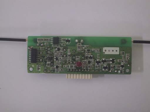
PVQDSCAB004
May 26, 2004RF Keyless Entry System
Equipment Class
DSC - Part 15 Security/Remote Control Transmitter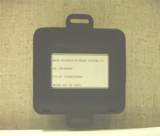
PVQDSCAR003
Jan 17, 2002Car Pager
Equipment Class
DSC - Part 15 Security/Remote Control Transmitter
PVQDSCAR002
Dec 19, 2001Car Alarm Remote Transceiver
Equipment Class
DSR - Part 15 Remote Control/Security Device Transceiver
PVQDSCAB001
Oct 22, 2001Car Alarm System
Equipment Class
DSR - Part 15 Remote Control/Security Device Transceiver