PWGDOLPHINWireless airPoint & airBridge
SmartBridges Pte Ltd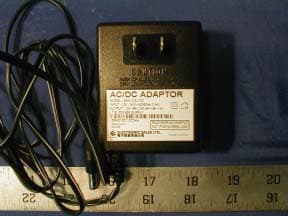
Click to zoom
Application Details
- Equipment Class
- DSS - Part 15 Spread Spectrum Transmitter
- Date of Grant
- Feb 20, 2002
- Application Purpose
- Original Equipment
- Date of Application
- Feb 20, 2002
- Equipment Note
- Wireless airPoint & airBridge
- Frequency Range
- 2412.67000000 - 2462.00000000
- Company
- SmartBridges Pte Ltd
- Country
- Singapore
Documents & Files
Document Text
Text extracted from the exhibit documents filed with the FCC. Open a document above to read the original.
Users Manual
http://www.smartbridges.com/ airBridge User Manual http://www.smartbridges.com/ Table of Contents 1. Contents of the package 2. Getting Started 2.1. Introduction 2.2. airBridge Setup Software 3. Installing airBridge 4. Configuring airBridge 5. Understanding Wireless Networking 6. Troubleshooting 7. FAQs 8. Common Problems and solutions 9. Service and Support 10. Appendix A - Technical specifications 11. Appendix B – Warranty Information 12. Appendix C – Declarations of conformity and regulatory Information http://www.smartbridges.com/ Contents of the package • 1 airBridge hardware • 1 Ethernet Cable 1.5 meter long • 1 airBridge Setup Software and User Manual CD • 1 External Antenna fixed to the airBridge • 1 Quick Install Guide • 1 AC Adapter • 1 Two Pin Plug for AC inlet for AC Adapter Fig 1.1 airBridge kit items Note : Unpack the airBridge kit and make sure that all the items are present . Please Contact your supplier in case of any damage or missing items. http://www.smartbridges.com/ Getting Started Introduction Thank you for purchasing smartBridges airBridge wireless Ethernet Client. The airBridge provides instant high speed wireless network connectivity for practically any PC equipped with ethernet based network card to a wireless Access Point. The air Bridge provides a complete solution to customers who require mobility and freedom in a wireless Local Area Network and wireless Internet connectivity through a gateway . The airBridge connects directly to the PC through the Ethernet port . airBridge Setup Software ensures easy installation and configuration through the Ethernet port . airBridge draws power from the wide range AC Adapter provided. airBridge Provides the user • Wireless connectivity for any PC with TCP /IP configured active network card and ethernet port to the wireless network. ( Infrastructure Mode ) • Wireless Connectivity between standalone PCs. (Adhoc Mode ) . airBridge can communicate with PC’s equipped with PCMCIA to RF client or USB to RF client or Ethernet to RF client in ADHOC mode . airBridge Setup Software Setup Software is a proprietary software developed by smartBridges for the easy installation and configuration of airBridge . It consists of, a. simpleMonitor – used to configure and set operational parameters of airBridge b. FWUpgrade – used to upgrade the firmware residing inside the internal flash memory of airBridge. http://www.smartbridges.com/ Minimum PC configuration required for Installation / Configuration of airBridge using setup Software. • An IBM compatible PC • Pentium processor ( 166 MHz or above ) • Microsoft Windows 98 / 98 SE/ NT4 ( SP6)/ 2000 / ME / XP • Memory Win 98 / 98 SE - 10 MB or higher Win 2000 / ME / XP – 10 MB or higher • Free Space on Hard disc – 10 MB required • SVGA Display ( 800x600 minimum ). • A CD ROM drive • Ethernet port with the functioning network card configured with TCP / IP . http://www.smartbridges.com/ Installing airBridge Installing hardware : Take out the airBridge from its packing and place it on the desk .Connect the AC adapter to the mains inlet . If the mains inlet is of different Type use necessary adapter . Plug the output cord of the AC adapter into The airBridge's 12V DC IN socket . • Please donot use other AC adapters because the polarity could be reverse or the current rating may not be adequate . Once the airBridge is powered the Orange LED PWR lights up indicating the device Is powered . Now connect the Ethernet port of airBridge to the Ethernet port of the computer through the Ethernet cable provided . On the airBridge the Orange LED shows POWER, Green LED indicates Ethernet activity, Blue LED indicates RF Link. By default the airBridge should automatically associate and work with the available Access Point on the network. If you want to select a specific Access Point or configure the additional parameters ( like WEP Keys ) please install the setup Software. Installing setup Software : 1. Insert the CD into the CDROM drive of the PC, the CD will autorun, If it does not autorun , browse the CD and run setup . exe 2. The installation will create the shortcuts in your program Menu at smartBridges/airBridge. o Firmware upgrade utility allows upgrades in firmware. o simpleMonitor which allows configuration of the airBridge. o Documentation shows the user guide in HTML version. o Uninstall the Setup Software. http://www.smartbridges.com/ The factory default parameters for the airBridge are • IP address – 192.168.0.22 • Subnet mask - 255.255.255.0 • Administrator Password : public • User password : public • authentication type : open key • WEP keys - None • Operating Channel : 11 • Regulatory Domain : ETSI. Note : The administrator should change his password so that configuration settings are not modified by unauthorized personnel, User password allows User to view the config settings but doesn’t allow to Change . Only administrator has the authority to change config setting. Hardware restoration of factory settings : Press the “reset” key on the back of the airBridge continuously for 15 seconds to restore back to the factory settings in case of any error or forgotten password. During restoration process the blue LED changes brightness . After restoring the factory settings reconfigure the airBridge again. http://www.smartbridges.com/ Configuring the airBridge The setup software installed on the windows PC will allow the user to modify the configuration and operating parameters of the airBridge and upgrade the latest firmware. It consists of 2 parts. • simpleMonitor – used to modify the configuration and operational parameters of airBridge. • FWUpgrade – used to upgrade the firmware residing inside the airBridge. At the time of installation the shortcuts for the simpleMonitor and FWUpgradeManager are created on your PC. The simpleMonitor The simpleMonitor Utility is provided to allow the user to configure the airBridge through the Ethernet connection. Linux/Unix Users: Though these operating systems are …
Text truncated - open the document above for the full version.
External Photos
EUT EXTERNAL PHOTOGRAPHS Chassis - Front View Chassis - Bottom View Chassis - Rear View Chassis - Side View Power Adapter - Top View
ID Label/Location Info
FCC PRODUCT LABELING AND WARNING STATEMENT FCC ID Label Specifications : Text is black or white in color and is left justified. Labels are silk- screened and shall be “permanently affixed” at a conspicuous location on the EUT. Proposed Label Location on EUT Bottom View of EUT FCC ID Label Location
Internal Photos
EUT EXTERNAL PHOTOGRAPHS Main Board - Component View Main Board - Solder View Main Board - Port View Main Board – Shielded Removed View Transmitter - Component View
Operational Description
smartBridges to the future... www.smartbridges.com Wireless Ethernet Client air Bridge Instant Wireless Access for all Ethernet Equipment smartBridges to the future... www.smartbridges.com Wireless Access Point air Point Higher power, Wider coverage, Lower Cost smartBridges to the future... www.smartbridges.com Go Wireless for less - Less Money, Less Mess, Less trouble... Sharing Broadband Internet access across many computers within a home or office is an established need today. The rapidly decreasing cost of Wireless LANs makes it more cost effective solution as compared with implementing their messy wired counterparts in many cases. Wireless Access points are the essential and perhaps the most important part of a wireless infrastructure and smartBridges brings to you the best in the business. airPoint™ - Wireless Access Point that's making Waves airPoint™ is a high performance, long range and easy to install Wireless Access point for Home and small office infrastructure requirements. airPoint™ provides wireless freedom and flexibility to work anywhere in the office or at home. LongRange™ Radio Performance that goes the Distance airPoint™ features LongRange™ wireless design that provides 100 mW radio power to deliver High data throughput and long operating range. smartBridges' superior design of the radio receiver enhances the sensitivity to incredible -95 dBm level. These superior receiver and transmitter characteristics result in the long-range wireless coverage of up to 800 meters (2640 feet) at 11 Mbps of data rate in free open space. At a lower speed of 1Mbps, the range has been tested up to 1 Mile (1600m). Better range translates directly into lower wireless infrastructure cost when the need is to cover a large area. Industry Standard compliant for Inter-operability airPoint™ is based on the IEEE 802.11b industry standard prescribed for Wireless LANs. Automatic radio tuning technology is used during manufacturing to ensure that the airPoint™ can inter-operate with any standard compliant device. airPoint™ has been tested for reliable operation with the wireless equipment from various leading manufacturers. Multi-Featured Security airPoint™ is equipped with a choice of security levels to protect the data. It comes with standard Wi-Fi prescribed Wired Equivalent Privacy (WEP) security using 40/64 bit Key. Additionally airPoint™ also offers enhanced 128-bit key encryption for superior data protection. Another key security features built into airPoint™ includes MAC level security that restricts the permitted access to pre-registered wireless clients base on their MAC ID. simpleMonitor™ The Intuitive Network Management Tool airPoint™ is supported by simpleMonitor™, an advanced Management tool, which is specifically designed to simplify wireless network management complexities. simpleMonitor™ is designed using Open System architecture. It utilizes popular network management standards (SNMP, MIB) to manage the wireless-centric network parameters such as, Channel selection, Network association, data rate, and site survey. Its graphical user interface is extremely intuitive for navigating, examining, and managing the wireless network. Dynamic Rate Scaling To increase the data range and ensure wireless network connectivity, airPoint™ adopts Dynamic Rate Scaling, thus always seeking to connect at 11 Mbps then automatically scaling to 5.5 Mbps, as well as 2 Mbps and 1 Mbps .When the signal strength increases, its speed also increases until it reaches the optimal rate, ensuring the highest level of service and the best continuity for data transmission. Power over Ethernet option available In many cases multiple access points are required to be installed to cover a certain area. It becomes a problem to find a power point next to many locations where access points are required to be installed for optimum Radio performance. airPoint™ can also be powered through the Ethernet cable by using the optional power injector available from smartBridges. Range: Outdoor, Noise Free open space Line of Sight: 800 meters at 11Mbps 1600 meters at 1Mbps Antenna: External with 2.2 dBi Gain Security: 40/64 and 128 bit Wired Equivalent Protection Management : SNMP (MIB, Tarps) : TFTP (for Firmware download) Roaming: Supported as per IEEE 802.11b Power Source: AC Adapter 100~230 V AC 50/60 Hz LED Indicators: Power, Ethernet Link , Transmission Operating Temp: 0 to +55 0 C (operating) Humidity (non -condensing): 10 to 85 % typical Dimensions: L 122mm; W 42mm; H 118mm Weight: 160 g Technical Specifications Product No: SB2400 Standards: IEEE 802.1b, IEEE 802.3 System Interface: Ethernet RJ45 (10/100Mbps) Data Rate: 11Mbps -CCK Auto Fall Back 5.5 Mbps - CCK 2Mbps - DQPSK 1Mbps - DBPSK Frequency Band: 2400 - 2483.4 MHz Wireless Medium: DSSS No. of Channels: 14 Channels (Over laping) 11 to North America, 14 Japan,13 Europe(ETSI) Modulation: DQPSK / DBPSK / CCK Output Power: 100mW (Max) Receiver Sensitivity: - 95 dBm smartBridges to the future... www.smartbridges.com Variety of Applications Finally, Internet everywhere at home There are many contentions in a family life. Internet access need not be one of them. The broadband Internet connection can now be shared instantly between the Living room PC, the PC in the study, Junior's PC or the notebook that you brought home to work. Going further, you can also share files, MP3 music or digital pictures between all these computers. Installing an airPoint™ is a safe long term investment. You can be at peace of mind that as you add more computers, Wireless VoIP phones or a 802.11b compatible refrigerator when it becomes available, your workhorse wireless LAN is ready to receive and interoperate with them. You continue to reap benefits from airPoint's superior range and quality as you add new gizmos to your wireless world. SOHO that even the corporations are jealous of MIS and ERP systems running on omni-present corporate LANs have been a major driving force behind efficiency of la…
Text truncated - open the document above for the full version.
Test Report
Note: This test report is specially limited to the above client company and the product sample only. It may not be duplicated without prior written consent of Bay Area Compliance Laboratory Corporation. This report must not be used by the client to claim product endorsement by NVLAP or any agency of the U.S. Government. FCC PART 15 SUBPART C EMI MEASUREMENT AND TEST REPORT For smartBridges Pte Ltd 10 Anson Road #22-14 International Plaza Singapore 079903 FCC ID: PWGDOLPHIN February 14, 2002 This Report Concerns: Original Report Equipment Type: Wireless airPoint & airBridge Test Engineer: Jeff Lee Test Date: February 1, 2002 Reviewed By: John Y. Chan – Engineering Manager Prepared By: Bay Area Compliance Laboratory Corporation 230 Commercial Street Sunnyvale, CA 94085 Tel: (408) 732-9162 Fax: (408) 732 9164 smartBridges Pte Ltd FCC ID: PWGDOLPHIN Report # DOLPHIN_Rpt FCC Part 15.247 Test Report Page 2 of 29 TABLE OF CONTENTS 1 - GENERAL INFORMATION..................................................................................................................................4 1.1 PRODUCT DESCRIPTION FOR EQUIPMENT UNDER TEST (EUT) ..............................................................................4 1.2 OBJECTIVE.............................................................................................................................................................4 1.3 RELATED SUBMITTAL(S)/GRANT(S).......................................................................................................................4 1.4 TEST METHODOLOGY............................................................................................................................................4 1.5 TEST FACILITY.......................................................................................................................................................4 1.6 TEST EQUIPMENT LIST AND DETAILS.....................................................................................................................5 1.7 LOCAL SUPPORT EQUIPMENT LIST AND DETAILS...................................................................................................6 1.8 HOST SYSTEM CONFIGURATION LIST AND DETAILS..............................................................................................6 1.9 EXTERNAL I/O CABLING LIST AND DETAILS.........................................................................................................6 2 - SYSTEM TEST CONFIGURATION.....................................................................................................................7 2.1 JUSTIFICATION.......................................................................................................................................................7 2.2 EUT EXERCISE SOFTWARE....................................................................................................................................7 2.3 SPECIAL ACCESSORIES...........................................................................................................................................7 2.4 SCHEMATICS / BLOCK DIAGRAM...........................................................................................................................7 2.5 EQUIPMENT MODIFICATIONS.................................................................................................................................7 2.6 CONFIGURATION OF TEST SYSTEM.........................................................................................................................8 2.7 TEST SETUP BLOCK DIAGRAM...............................................................................................................................8 3 - SUMMARY OF TEST RESULTS..........................................................................................................................9 4 - CONDUCTED OUTPUT POWER MEASUREMENT......................................................................................10 4.1 STANDARD APPLICABLE......................................................................................................................................10 4.2 MEASUREMENT PROCEDURE................................................................................................................................10 4.4 TEST RESULT.......................................................................................................................................................10 5 - SPURIOUS EMISSION.........................................................................................................................................12 5.1 STANDARD APPLICABLE......................................................................................................................................12 5.2 MEASUREMENT PROCEDURE................................................................................................................................12 5.3 MEASUREMENT DATA..........................................................................................................................................12 6 - POWER DENSITY ................................................................................................................................................14 6.1 STANDARD APPLICABLE......................................................................................................................................14 6.2 MEASUREMENT PROCEDURE................................................................................................................................14 6.3 TEST RESULTS.....................................................................................................................................................14 7 - 6DB BANDWIDTH................................................................................................................................................16 7.1 STANDARD APPLICABLE......................…
Text truncated - open the document above for the full version.
Test Setup Photos
CONDUCTED AND RADIATED SETUP PHOTOGRAPHS Conducted Emission - Front View Conducted Emission - Rear View Radiated Emission - Front View Radiated Emission - Rear View
Contact Information
Applicant
C. J. Balakrishnan(Engineering Director)
Test Firm
Bay Area Compliance LaboratoryJohn Chan
Technical Specifications
| # | Rule Parts | Frequency Range | Power Output |
|---|---|---|---|
| 1 | 15C | 2.41 GHz - 2.46 GHz | 98.40 mW |
Other Applications from SmartBridges Pte Ltd
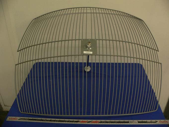
PWGNEXUS2
Sep 01, 2005802.11a/b/g MiniPCI WLAN Card
Equipment Class
DTS - Digital Transmission System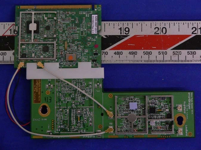
PWGNEXUS1
Apr 11, 2005IEEE 802.11a MiniPCI WLAN Card
Equipment Class
DTS - Digital Transmission System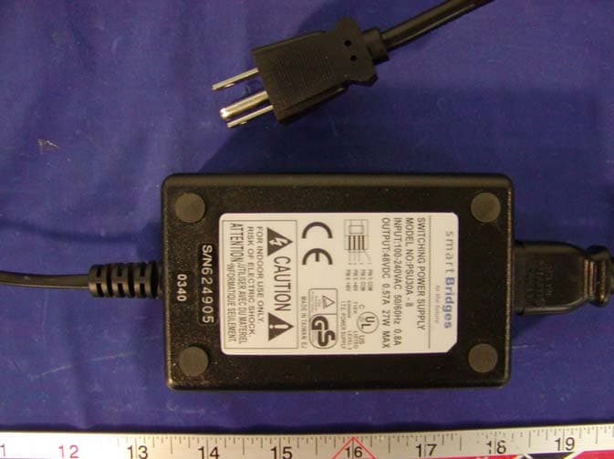
PWGSPEEDTRAP2
Mar 16, 2004airPoint XO2
Equipment Class
DTS - Digital Transmission System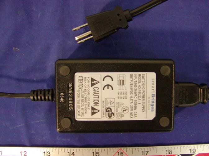
PWGSPEEDTRAP
Mar 16, 2004airPoint XO
Equipment Class
DTS - Digital Transmission System
PWGAIRPOINTPRO
Apr 29, 2002Wireless AirPointPRO
Equipment Class
DSS - Part 15 Spread Spectrum Transmitter