PWGNEXUS1IEEE 802.11a MiniPCI WLAN Card
SmartBridges Pte Ltd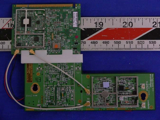
Click to zoom
Application Details
- Equipment Class
- DTS - Digital Transmission System
- Date of Grant
- Apr 11, 2005
- Application Purpose
- Original Equipment
- Date of Application
- Apr 11, 2005
- Equipment Note
- IEEE 802.11a MiniPCI WLAN Card
- Frequency Range
- 5725.00000000 - 5850.00000000
- Company
- SmartBridges Pte Ltd
- Country
- Singapore
Documents & Files
Document Text
Text extracted from the exhibit documents filed with the FCC. Open a document above to read the original.
Users Manual
FCC ID PWG NEXUS 1 1 Installation Manual smartBridges model SB3000 IEEE 802.11a MiniPCI WLAN Card Installation Manual Version 0.8 FCC ID PWG NEXUS 1 2 Installation Manual Table of Contents 1-INTRODUCTION.......................................................................................3 2-INSTALLATION PROCEDURE...............................................................3 2.1 NEXUS 3010 Back Haul Device for Out door... ................................3 2.2 INSTALLING THE MINIPCI CARD SB 3000 INTO NEXUS 3010.. .3 2.3 NEXUS 3010 software ...................................................................4 2.4 User Manual for NEXUS 3010 ..............................................4 2.4.1 Activating Link ................................................................4 2.4.2 Mounting the unit.............................................................9 2.4.3 Wireless LAN Installation and Authorization ............................12 2.4.4 Label Fixing ...................................................................12 3-REGULATORY INFORMATION................................................................13 3.1 FCC INFORMATION TO USER...........................................................13 3.2 FCC GUIDELINES FOR HUMAN EXPOSURE....................................13 3.3 FCC ELECTRONIC EMISSION NOTICES...........................................13 3.4 FCC RADIO FREQUENCY INTERFERENCE STATEMENT.............14 3.5 EXPORT RESTRICTIONS.....................................................................14 4-TECHNICAL SPECIFICATIONS................................................................15 FCC ID PWG NEXUS 1 3 Installation Manual 1. Introduction The smartBridges SB3000 is a complete wireless high speed Network Interface Card (NIC) used for Point to Point Links with external antennas . Developed by modifying GlobespanVirata ISL39200M WLAN NIC, it conforms to the IEEE 802.11a protocol , works in point to point mode and operates in the 5725-5850 MHz frequency band. The device shall not be used in any application other than Point to Point mode. 1. The module has Radio PCB and Booster PCB glued together inseparably with epoxy based potting compound . Any attempt to separate the PCB’s will destroy both the PCB’s irrepairably . Booster is an amplifier which keeps intact spectral mask and offers higher receiver sensitivity for the radio. This platform is used to enhance Nexus features. 2. Antennas qualified with the device are 32dBi Parabolic Dish , 29dBi Parabolic grid , 14 dBi Panel . No other antenna is allowed for use with the device. • Fully compliant with the IEEE 802.11a WLAN standards for Point to point links • FCC Certified Under Part 15 (pending) to Operate in the 5725-5850 MHz Band • Support for 54, 48, 36, 24, 18, 12, 9, and 6 Mbps OFDM • Driver Supports Microsoft Windows ® 98/SE, ME, XP and 2000 (SR1) 3. Installation Procedure SB 3000 has to be installed inside smartBridges NEXUS 3010 etc out door specified back haul devices . 3.1 NEXUS 3010 BackHaul device for outdoor application NEXUS 3010 is a Back Haul Point to Point link for carrying high data traffic . It uses Intel IXP 425 BCT a powerful processor to run the application and provide high security . It provides two Ethernet ports for connection to network devices or PC . Antenna is connected to the NEXUS unit . NEXUS 3010 is meant for out door application . It has to be mounted on Tower or roof top along with the antenna . It has all mounting hardware for this purpose . 3.2 Installing SB 3000 into NEXUS 3010 The module SB 3000 is normally installed into NEXUS 3010 in the factory at the time of manufacturing . NEXUS 3010 has mini PCI connector ( socket ). The Radio module SB 3000 can directly fit into the NEXUS unit and is fixed by screws to the mounting pillars shown . FCC ID PWG NEXUS 1 4 Installation Manual IXP 425 communicates with the Radio module and routes the data signals with necessary mini PCI format and controlling software . The units are run by software resident in the memory IC’s . SB 3010 can communicate to another SB 3010 only . The second device can be connected only when its MAC number is written into the first device . Channel blocking is provided by the software control which does not allow the user to select un authorized channels . 3.3 NEXUS 3010 Software NEXUS 3010 runs on its own software and does not require external PC software . PC provides Graphic User Interface and displays all controls and allows the user to configure the units . One unit is configured as Root device and another is configured as Remote Client . Root is master device and Client is slave in configuration . This configuration is required for networking purposes . Channel setting and output power control and client authentication are main functions of master . Slave gets wireless signals , decodes them and outputs them through Ethernet connector . The access points and other network devices are connected through the Ethernet link . Master normally connects to the internet back bone . 3.4 User Manual NEXUS 3010 SB 3000 module which is the main Transmitting and Receiving module inside NEXUS 3010 does not have independent user interface functionality . User controls the Radio module through NEXUS 3010 operating Instructions . The Instructions run as below . 2.4.1 Activating the Link It is recommended that you activate and configure the NEXUS 3010 link on your desktop prior to mounting the units in the field. Associating the units in advance will facilitate antenna alignment and simplify the overall installation procedure. Below are instructions on how to perform a basic association to allow antenna alignment. By default, one unit will operate in Root Bridge Mode and the other will operate in Remote Client Bridge Mode. Follow these steps to configure the first unit for Root FCC ID PWG NEXUS 1 5 Installation Manual Bridge Mode: First Unit Setup Note The default IP Address of NEXUS 3010 units is 192.168.1.1 and the default IP Mask i…
Text truncated - open the document above for the full version.
Cover Letter(s)
745 Toa Payoh Lorong 5, HBM Building #04-01, Singapore 319455 Tel: +65.6253.0100 Fax: +65.6353.5564 Email: [email protected] www.smartBridges.com Jan 22 , 2005 Federal Communications Commission Authorization and Evaluation Division Confidentiality Request regarding application for certification of FCC ID: PWG NEXUS1 Pursuant to Sections 0.457 and 0.459 of the Commission’s Rules, we hereby request confidential treatment of information accompanying this application as outlined below: 1. Block Diagram. 2. Schematic diagrams 3. Internal Photos The above materials contain trade secrets and proprietary information not customarily released to the public. The public disclosure of these materials may be harmful to the applicant and provide unjustified benefits to its competitors. Internal Photos may be held for short term confidentiality till 45 days and published later. The applicant understands that pursuant to Section 0.457 of the Rules, disclosure of this application and all accompanying documentation will not be made before the date of the Grant for this application. Sincerely, C.J.Balakrishnan , Engineering Director , 22 Jan 2005.
Cover Letter(s)
745 Toa Payoh Lorong 5, HBM Building #04-01, Singapore 319455 Tel: +65.6253.0100 Fax: +65.6353.5564 Email: [email protected] www.smartBridges.com To BACL Corporation 230 Commercial Street Sunny Vale , CA 94085 Sub : Nexus radio PCB Qualification Dear Sir , We have sent our Nexus Unit sB 3010 with Radio Module sB 3000 for qualification of Radio module . The radio module complies with the requirements of FCC part 15 Modular Transmitter Approval as below . 1. The Radio module has its own RF shield . It meets the Radiated emission limits of part 15 on its own . 2. The Data inputs for modulating are buffered by the baseband processor before modulating RF . No over modulation is possible by the amplitude or rate of Data input . The OFDM modulation applied to RF changes from 54 MBPs ( 64 QAM ) to 6 MBPs ( BPSK ) 3. The Radio Module has its own power supply regulator on board . 4. The Radio module uses a unique RF connector type FL ( propreitory ) for outputting RF . User can connect to the antenna only with FL to N cable provided by smartBridges Pte Ltd . 5. The Radio module is of stand alone type with mini PCI interface . It can be connected to any computer with mini PCI interface . 6. The Radio Module is installed in Nexus unit which will have a label “ Unit contains module with FCC ID : PWG NEXUS1 “ 7. The Radio Module is intended for use with Nexus unit under FCC 15.247 providing point to point wireless links . The operating requirements are described in the user manual enclosed for the Nexus unit . 8. The Radio Module complies with the RF exposure requirements . So We request our Radio Module SB 3000 be tested and qualified as modular transmitter. Thanks and Best Regards, C.J.Balakrishnan , Engineering Director , 14 Feb 2005 .
External Photos
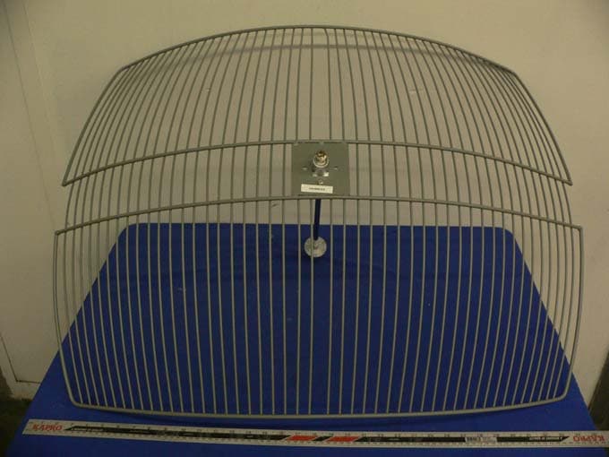
EXHIBIT C - EUT EXTERNAL PHOTOGRAPHS EUT – Top View EUT – Bottom View Antenna GD58 – Front View Antenna GD58 – Rear View Antenna PA58– Front View Antenna PA58 – Rear View Antenna DA58 – Front View Antenna DA58 – Rear View
ID Label/Location Info
EXHIBIT A - FCC ID LABEL INFORMATION Proposed FCC ID Label Proposed Label Location on EUT Bottom View of EUT /FCC ID Label
Internal Photos
EXHIBIT C - EUT INTERNAL PHOTOGRAPHS EUT – Top View EUT – Bottom View Board 1 Top View Board 1 Bottom View Board 2 Top View Board 2 Bottom View
Operational Description
745 Toa Payoh Lorong 5, HBM Building #04-01, Singapore 319455 Tel: +65.6253.0100 Fax: +65.6353.5564 Email: [email protected] www.smartBridges.com OPERATIONAL DESCRIPTION OF SB 3000 WLAN CARD SB 3000 is a wireless LAN card operating with 802 .11 a specs in frequency band 5.725 ~ 5.85 GHz band with OFDM modulation at different data rates 54 MBPs to 6 MBPs selected automatically . It consists of a MAC ( Media Access Controller ) , RF converter , filters , power amplifier , Transmit Receive switch and RF output connector ( FL type ) Transmit Path : The MAC controller takes the Data signals coming from the mini PCI port of a PC or other unit like NEXUS 3010 . It converts the Digital signals with headers and security wep keys to conform to 802.11a specs . The signal flows to the baseband processor which is part of the MAC controller and gets converted into differential OFDM signals . The OFDM data rates are controlled by the MAC controller depending upon the noise conditions in the wireless transmission path . The differential OFDM signals are applied to the RF converter . RF converter is of Zero IF type and uses an external VCO running at 11 ~ 12 GHz . Output is at 5.725 ~ 5.85 GHz in Transmit mode. RF output from the RF converter is passed through attenuator and filter to the power amplifier . Power amplifier provides the output power required . Output of the power amplifier is taken through a Band Pass Filter , Transmit Receive Switch to the RF connector . Receive Path : Received RF signals are taken from the RF connector , through the Transmit Receive Switch to the receiver Band Pass Filter and Low Noise pre Amplifier . The RF signal passes to the RF converter IC . The RF converter converts the RF to baseband signals in the Receive mode . Simultaneous Transmit and Receive actions are not allowed in the RF converter IC . The MAC controller receives the baseband signals . The baseband signals are decoded and headers and security keys removed and retrieved digital signals are applied to the PCI connector from where it flows into the PC or NEXUS 3010 unit .
Operational Description
PAWDA5x-32 ...DATA SHEET... Parabolic Dish Antenna 5 GHz Operation Features • High Gain 32 dBi Antenna • Adjustable tilt pole mount • Vertical or Horizontal Polarization • Type N Female Connector • DC Grounded for lightning protection • Rugged, Lightweight and Waterproof Applications • 5.8 GHz ISM Band Applications • 802.11a Wireless Data • 5.3GHz UNII Band Applications • Long Distance Backhaul Data Links • Point to Point Data Links • Building to Building High Speed Links Description The Parabolic Dish Antenna systems offered by Pacific Wireless are constructed of an aluminum alloy dish with powder coat paint finish for excellent mechanical, electrical and environmental performance. The parabolic reflector is made with a special one-step molding technology which achieves excellent consistency and long term stability. They come complete with universal galvanized steel, powder coat paint mounting system for pole mount applications. Because of its’ superb electrical performance and mechanical stability, the parabolic dish antenna can be used in a wide variety of high performance 5GHz wireless applications. An optional Fiberglass Radome is available for added environmental protection. Specifications Parameter Min Typ Max Units Frequency Range DA58 DA57 DA53 5725 5470 5150 5850 5725 5350 MHz Gain DA58 DA57 DA53 32.5 32 31 dBi Input Return Loss (S 11 ) -14 dB VSWR 1.5:1 3db Beam Angle 4 Deg Cross Pole -34 dB Front to Back 38 dB Side Lobe -30 dB Impedance 50 OHM Input Power 100 W Pole Diameter (OD) 1.5 (38) 3.0 (76) Inch (mm) Operating Temperature -40 +70 Deg C Rated Wind Velocity 125 mph Weight 22 (10) Lbs (Kg) Dimensions (Dia) 35.4 (900) Inch (mm) Pacific Wireless 693 E Draper Heights Way Suite 210 Draper, UT 84020 TEL (801) 572-3024 FAX (801) 572-3025 www.pacwireless.com DA58-32 100 MPH 125 MPH 100 MPH w/ ½”Radial Ice 256 400 258 w/Radome 100 MPH 125 MPH 100 MPH w/ ½”Radial Ice 111 173 181 Wind Loading PAWDA5x-32 Specifications Subject to Change Without Notice PAWDA58-32 Spec Rev 2 16-Jun-04 Page 2 Antenna Patterns Notes: • All shipments F.O.B. Bluffdale, UT 84065 • All antennas carry a 2 Year Warranty System Ordering: DA58-32 32.5dBi 5.725GHz to 5.850GHz Parabolic Dish Antenna DA57-32 32dBi 5.470GHz to 5.725GHz Parabolic Dish Antenna DA53-31 31dBi 5.150GHz to 5.350GHz Parabolic Dish Antenna DA5-32 RADOME Radome Kit for 0.9M Parabolic Dish Antenna For further information contact: Pacific Wireless 693 E Draper Heights Way Suite 210 Draper, UT 84020 TEL (801) 572-3024 FAX (801) 572-3025 www.pacwireless.com Optional Fiberglass Radome HPlane – Horizontal/Azimuth EPlane – Vertical/Elevation GD5x ...DATA SHEET... Grid Dish Parabolic Antenna 5150 to 5825 MHz Operation Features • 22dBi , 26dBi and 29dBi Models Available • Rugged and Weatherproof • Ultra Low Wind Loading and Low Visual Impact • Vertical or Horizontal Polarization • Type N Female Connector Applications • 5GHz Wireless LAN Applications • Point to Point Backhaul Description The 5GHz parabolic grid directional antennas offered by Pacific Wireless utilize a unique patented parabolic grid design with compact high performance feed. The antennas are constructed of welded steel wires which are galvanized and then powder coat painted with a light gray epoxy paint. The wire grid semi-parabolic design offers unsurpassed low wind loading while maintaining good RF performance. The compact low visual impact attractive styling blends well in almost any application. Mounting is simplified with the Pacific Wireless bracket system made of galvanized steel with stainless steel hardware. The antenna comes with a bulkhead N Female connector standard. Specifications Parameter Model Min Typ Max Units Frequency Range GD58 GD57 GD53 5725 5470 5150 5825 5725 5350 MHz Gain GD58-22 GD58-26 GD58-29 GD5x-21 GD5x-25 GD5x-28 22 26 29 21 25 28 dBi Horizontal Beamwidth GD5x-22/21 GD5x-26/25 GD5x-29/28 10 6 4 Deg Vertical Beamwidth GD5x-22/21 GD5x-26/25 GD5x-29/28 11 6 5 Deg Front to Back GD5x-22/21 GD5x-26/25 GD5x-29/28 25 30 25 dB VSWR 1.5:1 Impedance 50 OHM Input Power 100 W Operating Temp -40 +70 Deg C Pole Size 1” (25) 2” (50) In (mm) Weight GD5x-22/21 GD5x-26/25 GD5x-29/28 3 (1.4) 6 (2.7) 11 (5) Lbs. (kg) Dimension (W x L) GD5x-22/21 GD5x-26/25 11.8” x 15.7” (300 x 400) 16.8” x 24” (427 x 610) In (mm) Pacific Wireless 693 E Draper Heights Way Suite 210 Draper, UT 84020 TEL (801) 572-3024 FAX (801) 572-3025 www.pacwireless.com GD58-22 VPOL GD5x Specifications Subject to Change Without Notice GD5x Spec Rev 4 15 Sept 2004 Page 2 Parameter Model Min Typ Max Units GD5x-29/28 28.5 x 36” (724 x 914) Bracket Tilt +/-45 Deg Antenna Patterns @ 5.8GHz System Ordering: GD58-22 5.7-5.8GHz 22dBi Directional Antenna GD58-26 5.7-5.8GHz 26dBi Directional Antenna GD58-29 5.7-5.8GHz 29dBi Directional Antenna GD57-21 5.4-5.7GHz 21dBi Directional Antenna GD57-25 5.4-5.7GHz 25dBi Directional Antenna GD57-28 5.4-5.7GHz 28dBi Directional Antenna GD53-21 5.1-5.3GHz 21dBi Directional Antenna GD53-25 5.1-5.3GHz 25dBi Directional Antenna GD53-28 5.1-5.3GHz 28dBi Directional Antenna For further information contact: Wind Loading 100 MPH 125 MPH 100MPH with ½” Radial Ice GD58-22 10 15.6 48 GD58-26 20 31 99 GD58-29 41 64 257 Pacific Wireless 693 E Draper Heights Way Suite 210 Draper, UT 84020 TEL (801) 572-3024 FAX (801) 572-3025 www.pacwireless.com GD58-22 HPOL GD58-26 HPOL GD58-26 VPOL Notes: • All shipments F.O.B. Bluffdale, UT 84065 • All antennas carry a 2 Year Warranty GD58-29 HPOL GD58-29 VPOL GD58-22 VPOL PA58 ...DATA SHEET... Flat Panel TriBand Antenna 5150 to 5825 MHz Operation Features • High Gain / Low Profile / Tri Band • Pole Mount or Surface Mount • Rugged and Weatherproof • Vertical or Horizontal Polarization • Type N Female Connector Applications • 5GHz Wireless LAN Applications • Client Antennas • 802.11a Applications • OEM wireless data Description The 5GHz Tri-Band Flat Panel Directional antennas by Pacific Wireless offer high gain in a thin low profile package. The antennas…
Text truncated - open the document above for the full version.
RF Exposure Info
§1.1307 & §2.1093 - RF EXPOSURE According to §2.1093 and §1.1310, systems operating under the provisions of this section shall be operated in a manner that ensures that the public is not exposed to radio frequency energy level in excess of the Commission’s guidelines. According to §1.1310 and §2.1093 RF exposure is calculated. Limits for General Population/Uncontrolled Exposure Frequency Range (MHz) Electric Field Strength (V/m) Magnetic Field Strength (A/m) Power Density (mW/cm 2 ) Averaging Time (minute) Limits for General Population/Uncontrolled Exposure 0.3-1.34 614 1.63 *(100) 30 1.34-30 824/f 2.19/f *(180/f 2 ) 30 30-300 27.5 0.073 0.2 30 300-1500 / / f/1500 30 1500-100,000 / / 1.0 30 f = frequency in MHz * = Plane-wave equivalent power density MPE Prediction Predication of MPE limit at a given distance Equation from page 18 of OET Bulletin 65, Edition 97-01 S = PG/4πR² Where: S = power density P = power input to antenna G = power gain of the antenna in the direction of interest relative to an isotropic radiator R = distance to the center of radiation of the antenna Maximum peak output power at antenna input terminal: 11.83 (dBm ) Maximum peak output power at antenna input terminal: 15.24 (mW) Predication frequency: 5800 (MHz) Antenna Gain (typical): 32.5 (dBi) antenna gain: 1778.28 (numeric) Prediction distance: 47(cm) Power density at predication frequency at 47 cm: 0.98 (mW/cm 2 ) MPE limit for uncontrolled exposure at prediction frequency: 1.0 (mW/cm 2 ) Test Result The EUT is a outdoor device. The prediction distance is 47cm. The Power density at predication frequency at 47 cm is 0.98 mW/cm 2 within the limit of 1.0 mW/cm 2 .
Test Report
Note: The test report is specially limited to the above company and the product model only. It may not be duplicated without prior written consent of Bay Area Compliance Laboratory Corporation. This report must not be used by the client to claim product certification, approval, or endorsement by NVLAP, NIST or any agency of the US Government. FCC 15.247 EMI MEASUREMENT AND TEST REPORT For SmartBridges Pte Ltd 745, TOA PAYOH LORONG 5, #04-01 HBM BUILDING, SINGAPORE 319455 FCC ID: PWGNEXUS1 This Report Concerns: Original Report Equipment Type: IEEE 802.11a MiniPCI WLAN Card Test Engineer: Snell Leong Report No.: R0501203 Report Date: 2005-02-16 Reviewed By: Daniel Deng Prepared By: Bay Area Compliance Laboratory Corporation (BACL) 230 Commercial Street Sunnyvale, CA 94085 Tel: (408) 732-9162 Fax: (408) 732 9164 SmartBridges Pte Ltd FCC ID: PWGNEXUS1 Report # R0501203Rpt.doc Page 2 of 36 FCC 15.247 Report TABLE OF CONTENTS GENERAL INFORMATION.......................................................................................................................................4 PRODUCT DESCRIPTION FOR EQUIPMENT UNDER TEST (EUT) ....................................................................................4 OBJECTIVE...................................................................................................................................................................4 RELATED SUBMITTAL(S)/GRANT(S).............................................................................................................................4 TEST METHODOLOGY..................................................................................................................................................4 TEST FACILITY.............................................................................................................................................................4 SYSTEM TEST CONFIGURATION ..........................................................................................................................6 JUSTIFICATION.............................................................................................................................................................6 BLOCK DIAGRAM.........................................................................................................................................................6 EQUIPMENT MODIFICATIONS.......................................................................................................................................6 LOCAL SUPPORT EQUIPMENT LIST AND DETAILS........................................................................................................6 EXTERNAL I/O CABLING LIST AND DETAILS...............................................................................................................6 CONFIGURATION OF TEST SYSTEM..............................................................................................................................7 TEST SETUP BLOCK DIAGRAM.....................................................................................................................................7 SUMMARY OF TEST RESULTS FOR FCC PART 15............................................................................................8 §1.1307(B)(1) & §2.1093 - RF EXPOSURE.................................................................................................................9 ANTENNA REQUIREMENT ....................................................................................................................................10 §15.207(A) - CONDUCTED EMISSION...................................................................................................................11 MEASUREMENT UNCERTAINTY..................................................................................................................................11 TEST SETUP................................................................................................................................................................11 RECEIVER SETUP........................................................................................................................................................11 TEST EQUIPMENT LIST AND DETAILS.........................................................................................................................11 TEST PROCEDURE......................................................................................................................................................11 ENVIRONMENTAL CONDITIONS..................................................................................................................................12 SUMMARY OF TEST RESULTS.....................................................................................................................................12 CONDUCTED EMISSIONS TEST DATA.........................................................................................................................12 PLOT OF CONDUCTED EMISSIONS TEST DATA...........................................................................................................13 §15.205 & §15.209 - RADIATED EMISSION...........................................................................................................18 MEASUREMENT UNCERTAINTY..................................................................................................................................18 TEST SETUP................................................................................................................................................................18 SPECTRUM ANALYZER SETUP....................................................................................................................................18 TEST EQUIPMENT LIST AND DETAILS.........................................................................................................................18 ENVIRONMENTAL CONDITIONS........…
Text truncated - open the document above for the full version.
Test Setup Photos
EXHIBIT B - TEST SETUP PHOTOGRAPHS Conducted Emission with External Power Adapter Conducted Emission with Notebook Power Adapter
Contact Information
Applicant
C. J. Balakrishnan(Engineering Director)
Test Firm
Bay Area Compliance LaboratoryJohn Chan
Technical Specifications
| # | Rule Parts | Frequency Range | Power Output |
|---|---|---|---|
| 1 | 15C | 5.72 GHz - 5.85 GHz | 200.00 mW |
Other Applications from SmartBridges Pte Ltd
PWGNEXUS2
Sep 01, 2005802.11a/b/g MiniPCI WLAN Card
Equipment Class
DTS - Digital Transmission System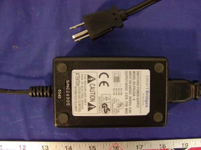
PWGSPEEDTRAP2
Mar 16, 2004airPoint XO2
Equipment Class
DTS - Digital Transmission System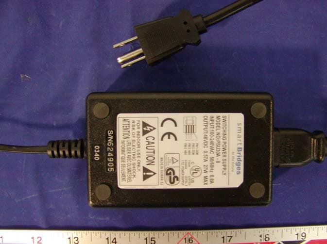
PWGSPEEDTRAP
Mar 16, 2004airPoint XO
Equipment Class
DTS - Digital Transmission System
PWGAIRPOINTPRO
Apr 29, 2002Wireless AirPointPRO
Equipment Class
DSS - Part 15 Spread Spectrum Transmitter
PWGDOLPHIN
Feb 20, 2002Wireless airPoint & airBridge
Equipment Class
DSS - Part 15 Spread Spectrum Transmitter