PWGSPEEDTRAP2airPoint XO2
SmartBridges Pte Ltd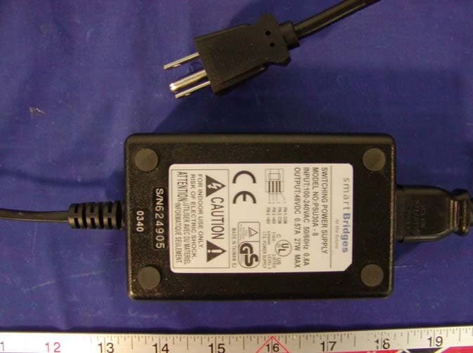
Click to zoom
Application Details
- Equipment Class
- DTS - Digital Transmission System
- Date of Grant
- Mar 16, 2004
- Application Purpose
- Original Equipment
- Date of Application
- Mar 16, 2004
- Equipment Note
- airPoint XO2
- Frequency Range
- 2412.00000000 - 2462.00000000
- Company
- SmartBridges Pte Ltd
- Country
- Singapore
Documents & Files
Document Text
Text extracted from the exhibit documents filed with the FCC. Open a document above to read the original.
Users Manual
airPoint XO ™ Series Wireless Access Points Quick Install Guide airPoint XO Series Page 2 of 24 Professional Installation airPoint XO and airPoint XO2 require installation by professional installer. Steps: • Choose the antenna from the antennas certified with airPoint XO / airPoint XO2 • The RF cable should be of 1 meter length, LMR 400 cable with N male connectors at both ends. • Set the power output of airPoint XO / airPoint XO2 using the procedure shown in "Configuring airPoint XO" / “ Configuring airPoint XO2 “. The RF output power can be adjusted to a maximum of +17dBm. • Keep safe distance of 32 centimeters away from the antenna. • Professional installation is required for all antennae. RF Safety Precaution airPoint XO , airPoint XO2 gives out electromagnetic Radiation through the antenna . . It is harmful to be in contact with the antenna or to be in close proximity when the airPoint XO or airPointXO2 when it is powered ON . The safe distance is 45 centimeters from the antenna . The indication for RF radiation is the lighting up of Blue LED on the device . airPoint XO Series Page 3 of 24 Table of Contents 1. airPoint XO™ Series.................................................................. 4 2. Package Contents ..................................................................... 6 3. Hardware Installation ................................................................. 6 4. Installing the airPoint XO™ Series ............................................ 8 4.1 Pole Mounting...................................................................... 9 4.2 Mounting the Antenna........................................................ 10 4.3 Cabling............................................................................... 11 4.4 LEDs Status....................................................................... 12 4.5 Protection........................................................................... 12 5. Service and Support ................................................................ 13 6. Frequently Asked Questions.................................................... 14 Appendix A – Specifications ........................................................ 16 Appendix B –Warranty, License and Copyrights ......................... 18 Appendix C -Declaration of Conformity ....................................... 19 airPoint XO Series Page 4 of 24 1. airPoint XO™ Series The smartBridges airPoint XO™ products are LongRange™, IEEE 802.11b compliant Access Point devices for deployment of Wireless Wide Area Networks (WWANs). The airPoint XO™ products deal with four key areas that are of vital importance in any WWAN network: Subscriber Bandwidth Management, Advanced Networking Capabilities, Remote Infrastructure Management and, Carrier-Class Reliability. Currently there are 2 models in the airPoint XO™ series 1. airPoint XO™ - Outdoor wireless access point with Bandwidth Management 2. airPoint XO 2 ™ - Dual radio outdoor wireless access point with Bandwidth Management With a suitable external Directional antenna the airPoint XO™ series can provide range of up to 32 Kilometers. All the access points in this series provide data rates up to 11Mbps making it one of the fastest Wireless Access Point family in the market. Encryption capability of 64 bits or 128 bits provides network security. The airPoint XO™ series can be used as an access point, client bridge, wireless bridge and wireless repeater to provide various networking functions. The dual radio XO 2 ™ can be configured to work in Full Repeater mode, Dual Access Point mode, Cell Extender mode and High Reliability Access Point mode. Designed to tolerate extreme weather conditions, the airPoint XO™ series provides a two-layered protection, through the IEEE 802.3af compliant, PoE Outdoor™ (Power over Ethernet) accessory for regulatory compliant installations. The radios are supported by multiple Network Processing Elements to handle heavy network loads. These devices can be remotely configured, monitored upgraded, reset and even power cycled, thus allowing ease of maintenance. Numerous applications like broadband connectivity to far flung neighborhood homes, wireless networking of PC's in a campus, wireless networking across waterways, roads, valleys and rough terrain are possible. The home PC gets connected to the Internet through the airPoint XO Series Page 5 of 24 airBridge series (Client devices) and the airPoint XO™ series (access points) wirelessly. Application Diagram for airPoint XO™ airPoint XO Access Point with Bandwidth Management Client Client Client Client Client Client Internet Backbone NOC airPoint XO Bandwidth limit of 512 kbps Bandwidth limit of 128 kbps Bandwidth limit of 256 kbps Bandwidth limit of 128 kbps Bandwidth limit of 512 kbps Bandwidth limit of 1 Mbps airPoint XO Internet Backbone Network Management Traffic Backhaul Connectivity NOC Internet Backbone airPoint XO 2 in Full Repeater mode airPoint XO 2 Client Client Client airPoint XO Series Page 6 of 24 Application Diagram for airPoint XO 2 ™ 2. Package Contents l airPoint XO™ or XO 2 ™ Unit l Power over Ethernet (PoE) Outdoor™, with 48 V power adapter and Wall Plate Unit (standard accessories provided with airPoint XO™ series) l Grounding Tag l Pole Mounting Kit : U Bracket, Nuts, Washers l Wall Mounting Kit : Wall plugs , Screws l airPoint XO™ Setup Software and User Manual CD l Quick Install Guide airPoint XO Series Page 7 of 24 3. Hardware Installation For airPoint XO™ and airPoint XO 2 ™ • Connect an outdoor rated shielded Ethernet CAT 5 / 5e cable to the RJ45 connector of the airPoint XO™ ( Located inside the weather proof connector ) to the ETH OUT of PoE Outdoor™ (Refer to the PoE Outdoor™ user guide for detailed instructions) • Connect the ETH IN RJ45 connector of the PoE Outdoor™ to the ETH Out of the Wall Plate Unit with proper CAT 5 / 5e cable . • Connect the ETH in of the Wall plate to the LAN port of the PC or network through CAT 5 / 5e cable • Conne…
Text truncated - open the document above for the full version.
Attestation Statements
http://www.smartbridges.com/ Email: [email protected] 745 Toa Payoh Lorong 5, #04-01 HBM Building, Singapore 319455 Tel: +65 6253 0100, Fax: +65 6353 5564 Dec 19 , 2003 Federal Communications Commission Authorization and Evaluation Division Confidentiality Request regarding application for certification of FCC ID: PWG SPEEDTRAP2 Pursuant to Sections 0.457 and 0.459 of the Commission’s Rules, we hereby request confidential treatment of information accompanying this application as outlined below: 1. Block Diagram. 2. Schematic diagrams The above materials contain trade secrets and proprietary information not customarily released to the public. The public disclosure of these materials may be harmful to the applicant and provide unjustified benefits to its competitors. The applicant understands that pursuant to Section 0.457 of the Rules, disclosure of this application and all accompanying documentation will not be made before the date of the Grant for this application. Sincerely, C. J . Balakrishnan Engineering Director
External Photos
EXHIBIT C - EUT PHOTOGRAPHS EUT (airPoint XO2) – Top View EUT (airPoint XO2) - Rear View EUT (airPoint XO2) – Port View EUT (PoE Outdoor) – Top View EUT (PoE Outdoor) - Rear View EUT (PoE Outdoor) – Port View PoE Outdoor - Adaptor View
ID Label/Location Info
EXHIBIT A - FCC ID LABEL INFORMATION Proposed FCC ID Label Specifications: Text is black or white in color and is left justified. Labels are silk-screened and shall be “permanently affixed” at a conspicuous location on the EUT. Proposed Label Location on Notebook Rear Side of the EUT / Label Location FCC ID: PWGSPEEDTRAP2 This device complies with Part 15 o the FCC Rules. Operation is subject to the following two conditions: (1) this device may not cause harmful interference, and (2) this device must accept any interference received, including interference that may cause undesired operation. 2.1875" 1.0"
Internal Photos
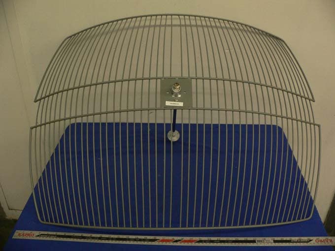
EUT (airPoint XO2) – Main Board Component View EUT (airPoint XO2) – Main Board Solder View EUT (airPoint XO2) - Board and Housing View EUT (PoE Outdoor) – Component View EUT (PoE Outdoor) – Solder View Radio A – Top View with Cover Radio A – Top View without Cover Radio A – Bottom View Radio B – Top View with Cover Radio B – Top View without Cover Radio B – Bottom View Closer View of Radio A and B’s Transceiver without Cover Antenna 1: WISP 24013-120PTNF 13dBi 120 degree, Sector Panel Top View Antenna 1: WISP 24013-120PTNF 13dBi 120 degree, Sector Panel Bottom View Antenna 2: WISP 24014-90PTNF 14dBi 90 Degree, Sector Panel Top View Antenna 2: WISP 24014-90PTNF 14dBi 90 Degree, Sector Panel Bottom View Antenna 3: WISP 24024 PTNF 24dBi parabolic Grid Front View Antenna 3: WISP 24024 PTNF 24dBi parabolic Grid Rear View Antenna 4: PAWOD24-12 12dBi Omni Directional Antenna View Antenna 5: PAWSA24-16 16.5dBi Horizontally Polarized 90 Degree Sector Antenna Top View Antenna 5: PAWSA24-16 16.5dBi Horizontally Polarized 90 Degree Sector Antenna Bottom View Antenna 6: PAWDC24-HD-PFIP 24dBi Die Cast Antenna Front View Antenna 6: PAWDC24-HD-PFIP 24dBi Die Cast Antenna Side View Antenna 7: PAWODH24-13 13dBi Horizontally Polarized Sector Antenna Top View Antenna 7: PAWODH24-13 13dBi Horizontally Polarized Sector Antenna Bottom View Antenna 8: PAWSA24-17 17dBi Vertically Polarized 90 Degree Sector Antenna Top View Antenna 8: PAWSA24-17 17dBi Vertically Polarized 90 Degree Sector Antenna Bottom View Antenna 9: PAWSA24-16 16.5dBi Vertically Polarized 120 Degree Sector Antenna Top View Antenna 9: PAWSA24-16 16.5dBi Vertically Polarized 120 Degree Sector Antenna Bottom View
Operational Description
airPoint XO 2 airPoint XO 2 is a dual-radio access point that offers all the features of the airPoint XO including Bandwidth Management, Advanced Networking and Carrier Class Features. In addition, modular control of the two radios enables many different configurations. The airPoint XO 2 can be used in high performance Cell Extender configuration for deploying low cost backhaul solution. It can be used as two Access Points in a box for simultaneous use to support large number of users or it can also be used as a highly reliable Access Point with Hot Standby for redundancy. The dual-radio design eliminates/minimizes throughput loss that would typically occur in these configurations when operating with a single radio. The multimode functionality offered by airPoint XO 2 is unrivalled and simplifies the deployment of Wireless Wide Area Networks. The flexibility of configurations that can be achieved with the airPoint XO 2 is quite unique and radically simplifies installations. These configurations (modes) make it possible to design and deploy efficient, high- performance wireless networks effortlessly and profitably. Full Repeater mode, with Bandwidth Management This mode is particularly useful to WISPs for covering very long distances without incurring throughput loss. In a typical scenario, if signals have to be repeated, the throughput is generally halved by the repeater. airPointXO 2 ’s Full Repeater mode overcomes the problems of lowered throughput and higher costs by configuring both back to back connected radios as repeaters. Eradicates throughput loss for repeaters Doubles signal relay distance Dual Access Point mode, with Bandwidth Management Using airPoint XO 2 a WISP can configure both the radios to access point mode in order to cover a larger geographical area. The Bandwidth management feature optimizes bandwidth utilization for each access point’s client group, as well as manages bandwidth allocation between the two radios. Enhances geographical coverage from a single device Reduces number of required installations lowering infrastructure costs Cell Extender mode, with Bandwidth Management airPoint XO 2 ’s dual radio system can be operated with one radio configured for dedicated backhaul connection to the NOC and the other radio configured as an access point. Faster speeds, better throughput Bandwidth management at PoP Reduced processing overheads, protocol conversion overheads etc High Reliability Access Point mode, with Standby Redundancy airPoint XO 2 is built to reinforce service reliability in outdoor wireless networks so as to enhance user satisfaction. WISPs can configure one of the radios to access point mode to provide broadband coverage to a designated area. The second radio can be configured as a hot standby for this access point. Enhanced network reliability and uptime Built in redundancy in the network Bandwidth Management for increased ROI The airPoint XO 2 provides bandwidth throttling of upload/download streams. The bandwidth control can be done using static tables or dynamically by RADIUS, along with authentication. The Wireless ISP can profile subscribers based on speed limits and identify bandwidth usage patterns. This opens up customer segmentation possibilities, leading to revenue maximization. The airPoint XO 2 provides traffic statistics. This helps the WISP to observe the behavior of network devices, traffic load fluctuations and other events, making it much easier to troubleshoot any problems, which might occur. The information available helps the WISP to optimize bandwidth utilization. WISPs can now easily provide services to more subscribers Easy Scalability & Roaming By distributing the bandwidth management function from the centralized NOC out to individual airPoint XO 2 access points, it is now possible to design scalable wide area networks. Bandwidth traffic policies can be set remotely from a central NOC. This avoids the need for backhauling all the data traffic to a single place, thus averting a choke point. All access points in the network controlled by one NOC not only brings convenience to network management but also enables mobile users to avail easy roaming facility Roaming users can cross over seamlessly from one cell to another within the same WISP network, without the need for authentication at every cross-over. Remote Management, Upgrades and Control airPoint XO 2 has built-in features to make device management both convenient and secure. It can provide access control lists and filters for SNMP traffic, as well as IP filtering. The airPoint XO 2 supports remote setting of radio parameters, firmware upgrade and restore defaults through SNMP. Further, the WISP can also monitor the temperature of the unit through the thermal sensing facility, which is policy based. The product supports SNMP based remote monitoring and management through simple NMS and simpleMonitor and has an embedded SNMP MIB. Long Range™ Radio Performance and Flexible Antenna Options airPoint XO 2 features LongRange™ wireless radio that delivers high data throughput over long operating range. With a suitable antenna airPoint XO 2 's range easily extends to 34 kilometers (21 Miles). The airPoint XO 2 has been FCC certified with many antenna configurations normally used by WISPs and outdoor wireless installers. Software controlled "Dial-a-Power" lets the installer control radio power output. Together, these features provide the much-needed flexibility to choose the right antenna with the pattern and gain characteristics conforming to local regulatory limits as well as coverage area requirements. The airPoint XO 2 supports 128 clients per radio. Reinforced Processing Capability for higher network loads airPoint XO 2 , with more raw processing power, surpasses other available devices allowing it to take on bigger network loads. The two radios with their individual slave processors coupled with the master processor of the unit can support enormous network loads. This makes th…
Text truncated - open the document above for the full version.
Operational Description
http://www.smartbridges.com/ Email: [email protected] PROFESSIONAL INSTALLATION MANUAL FOR 24 dBi Antenna SmartBridges Pte Ltd manufactures wireless OutDoor units airPoint XO model NO: SB 5200 and airPoint XO2 model NO: SB 5100 conforming to IEEE 802.11b spec operating in ISM band using external antennas. The 24 dBi antenna has to installed only in point to point application and not in point to multi point application . • The devices shall be installed by professional installers only . It is not to be installed by general public . • The devices shall not be sold to general public directly .The marketing channels are 1. Distributors who sell them to Wireless Internet Service Providers who are the installers . 2. Direct to Wireless Internet Service Providers through WebSales who are the installers • The Antenna shall be fixed in place and connected to the device by professional installer . The installer has to set the output power using Dial – a – Power utility . The installer has to key in the Antenna Gain and Loss of the cable (Standard Cable is 1 meter long LMR 400 with N male connectors at both ends ,loss 0.5 dB ) used to connect the device to the antenna . The software utility computes and displays maximum power settable for FCC domain . The RF output power can be set to a maximum of 17+dBm. If the installer tries to set a larger radiated power output a Warning Message appears on the screen “ Warning EIRP exceeds the maximum specified limits for the regulatory domain” . The installer has to reduce output power till the warning message disappears . 745 Toa Payoh Lorong 5, #04-01 HBM Building, Singapore 319455 Tel: +65 6253 0100, Fax: +65 6353 5564
RF Exposure Info
§1.1307(b)(1) & §2.1093 - RF EXPOSURE According to §15.247(b)(4) and §1.1307(b)(1), systems operating under the provisions of this section shall be operated in a manner that ensures that the public is not exposed to radio frequency energy level in excess of the Commission’s guidelines. According to §1.1310 and §2.1093 RF exposure is calculated. Limits for General Population/Uncontrolled Exposure Frequency Range (MHz) Electric Field Strength (V/m) Magnetic Field Strength (A/m) Power Density (mW/cm 2 ) Averaging Time (minute) Limits for General Population/Uncontrolled Exposure 0.3-1.34 614 1.63 *(100) 30 1.34-30 824/f 2.19/f *(180/f 2 ) 30 30-300 27.5 0.073 0.2 30 300-1500 / / f/1500 30 1500-100,000 / / 1.0 30 f = frequency in MHz * = Plane-wave equivalent power density MPE Prediction Predication of MPE limit at a given distance Equation from page 18 of OET Bulletin 65, Edition 97-01 S = PG/4πR² Where: S = power density P = power input to antenna G = power gain of the antenna in the direction of interest relative to an isotropic radiator R = distance to the center of radiation of the antenna Maximum peak output power at antenna input terminal: 17.27 (dBm) Maximum peak output power at antenna input terminal: 53.33 (mW) Prediction distance: 20 (cm) Predication frequency: 2400 (MHz) 1. WISP 24013-120PTNF, 13dBi 120 Degree, Sector Panel, Antenna Gain (typical): 13 (dBi) antenna gain: 19.95 (numeric) Minimum safe distance at predication frequency : 9.2 cm 2. WISP 24014-90PTNF, 14dBi 90 Degree, Sector Panel, Antenna Gain (typical): 14 (dBi) antenna gain: 25.12 (numeric) Minimum safe distance at predication frequency : 10.33 cm 3. PAWOD24-12, 12dBi Omni Directional, Antenna Gain (typical): 12 (dBi) antenna gain: 15.85 (numeric) Minimum safe distance at predication frequency : 8.2 cm 4. PAWSA24-16, 16.5dBi Horizontally Polarised 90 Degree Sector, Antenna Gain (typical): 16.5 (dBi) antenna gain: 44.67 (numeric) Minimum safe distance at predication frequency : 13.77 cm 5. PAWODH24-13, 13dBi Horizontally Polarized Sector, Antenna Gain (typical): 13 (dBi) antenna gain: 19.95 (numeric) Minimum safe distance at predication frequency : 9.2 cm 6. PAWSA24-17, 17dBi Vertically Polarized 90 Degree Sector, Antenna Gain (typical): 17 (dBi) antenna gain: 50.12 (numeric) Minimum safe distance at predication frequency : 14.58 cm 7. PAWSA24-16, 16.5 dBi Vertically Polarized 120 Degree Sector, Antenna Gain (typical): 16.5 (dBi) antenna gain: 44.67 (numeric) Minimum safe distance at predication frequency : 13.77 cm MPE limit for uncontrolled exposure at prediction frequency: 1 (mW/cm 2 ) Test Result The predicted minimum safe distance are as following: 1. WISP 24013-120PTNF, 13dBi 120 Degree, Sector Panel: predicted minimum safe distance is 9.2 cm. 2. WISP 24014-90PTNF, 14dBi 90 Degree, Sector Panel: predicted minimum safe distance is 10.33 cm. 3. PAWOD24-12, 12dBi Omni Directional: predicted minimum safe distance is 8.2 cm. 4. PAWSA24-16, 16.5dBi Horizontally Polarized 90 Degree Sector: predicted minimum safe distance is 13.77 cm. 5. PAWODH24-13, 13dBi Horizontally Polarized Sector: predicted minimum safe distance is 9.2 cm. 6. PAWSA24-17, 17dBi Vertically Polarized 90 Degree Sector: predicted minimum safe distance is 14.58 cm. 7. PAWSA24-16, 16.5 dBi Vertically Polarized 120 Degree Sector: predicted minimum safe distance is 13.77 cm. MPE Prediction For antenna WISP24024 PINF, 24 dBi Parabolic Grid and antenna PAWDC24-HD-PFIP, 24 dBi Die Cast, the maximum peak power at the antenna input terminal reduced to 16.2 dBm [41.6mW]. Predication of MPE limit at a given distance Equation from page 18 of OET Bulletin 65, Edition 97-01 S = PG/4πR² Where: S = power density P = power input to antenna G = power gain of the antenna in the direction of interest relative to an isotropic radiator R = distance to the center of radiation of the antenna Maximum peak output power at antenna input terminal: 16.2 (dBm) Maximum peak output power at antenna input terminal: 41.6 (mW) Prediction distance: 20 (cm) Predication frequency: 2400 (MHz) 1. WISP 24024 PTNF, 24 dBi Parabolic Grid, Antenna Gain (typical): 24 (dBi) antenna gain: 251.19 (numeric) Minimum safe distance at predication frequency : 8.92 cm 2. PAWDC24-HD-PFIP, 24 dBi Die Cast, Antenna Gain (typical): 24 (dBi) antenna gain: 251.19 (numeric) Minimum safe distance at predication frequency : 8.92 cm Test Result The predicted minimum safe distance are as following: 1. WISP 24024 PTNF, 24 dBi Parabolic Grid: predicted minimum safe distance is 8.92 cm. 2. PAWDC24-HD-PFIP, 24 dBi Die Cast: predicted minimum safe distance is 8.92 cm.
RF Exposure Info
§1.1307(b)(1) & §2.1093 - RF EXPOSURE According to §15.247(b)(4) and §1.1307(b)(1), systems operating under the provisions of this section shall be operated in a manner that ensures that the public is not exposed to radio frequency energy level in excess of the Commission’s guidelines. According to §1.1310 and §2.1093 RF exposure is calculated. Limits for General Population/Uncontrolled Exposure Frequency Range (MHz) Electric Field Strength (V/m) Magnetic Field Strength (A/m) Power Density (mW/cm 2 ) Averaging Time (minute) Limits for General Population/Uncontrolled Exposure 0.3-1.34 614 1.63 *(100) 30 1.34-30 824/f 2.19/f *(180/f 2 ) 30 30-300 27.5 0.073 0.2 30 300-1500 / / f/1500 30 1500-100,000 / / 1.0 30 f = frequency in MHz * = Plane-wave equivalent power density MPE Prediction Predication of MPE limit at a given distance Equation from page 18 of OET Bulletin 65, Edition 97-01 S = PG/4πR² Where: S = power density P = power input to antenna G = power gain of the antenna in the direction of interest relative to an isotropic radiator R = distance to the center of radiation of the antenna Maximum peak output power at antenna input terminal: 17.27 (dBm ) Maximum peak output power at antenna input terminal: 53.33 (mW) Prediction distance: 20 (cm) Predication frequency: 2400 (MHz) 1. WISP 24013-120PTNF, 13dBi 120 Degree, Sector Panel, Antenna Gain (typical): 13 (dBi) antenna gain: 19.95 (numeric) Minimum safe distance at predication frequency : 9.2 cm 2. WISP 24014-90PTNF, 14dBi 90 Degree, Sector Panel, Antenna Gain (typical): 14 (dBi) antenna gain: 25.12 (numeric) Minimum safe distance at predication frequency : 10.33 cm 3. PAWOD24-12, 12dBi Omni Directional, Antenna Gain (typical): 12 (dBi) antenna gain: 15.85 (numeric) Minimum safe distance at predication frequency : 8.2 cm 4. PAWSA24-16, 16.5dBi Horizontally Polarised 90 Degree Sector, Antenna Gain (typical): 16.5 (dBi) antenna gain: 44.67 (numeric) Minimum safe distance at predication frequency : 13.77 cm 5. PAWODH24-13, 13dBi Horizontally Polarized Sector, Antenna Gain (typical): 13 (dBi) antenna gain: 19.95 (numeric) Minimum safe distance at predication frequency : 9.2 cm 6. PAWSA24-17, 17dBi Vertically Polarized 90 Degree Sector, Antenna Gain (typical): 17 (dBi) antenna gain: 50.12 (numeric) Minimum safe distance at predication frequency : 14.58 cm 7. PAWSA24-16, 16.5 dBi Vertically Polarized 120 Degree Sector, Antenna Gain (typical): 16.5 (dBi) antenna gain: 44.67 (numeric) Minimum safe distance at predication frequency : 13.77 cm MPE limit for uncontrolled exposure at prediction frequency: 1 (mW/cm 2 ) Test Result The required minimum safe distance is at least 20 cm from the body of any user or nearby persons. MPE Prediction For antenna WISP24024 PINF, 24 dBi Parabolic Grid and antenna PAWDC24-HD-PFIP, 24 dBi Die Cast, the maximum peak power at the antenna input terminal reduced to 16.2 dBm [41.6mW]. Predication of MPE limit at a given distance Equation from page 18 of OET Bulletin 65, Edition 97-01 S = PG/4πR² Where: S = power density P = power input to antenna G = power gain of the antenna in the direction of interest relative to an isotropic radiator R = distance to the center of radiation of the antenna Maximum peak output power at antenna input terminal: 16.2 (dBm ) Maximum peak output power at antenna input terminal: 41.6 (mW) Prediction distance: 20 (cm) Predication frequency: 2400 (MHz) 1. WISP 24024 PTNF, 24 dBi Parabolic Grid, Antenna Gain (typical): 24 (dBi) antenna gain: 251.19 (numeric) Minimum safe distance at predication frequency : 8.92 cm 2. PAWDC24-HD-PFIP, 24 dBi Die Cast, Antenna Gain (typical): 24 (dBi) antenna gain: 251.19 (numeric) Minimum safe distance at predication frequency : 8.92 cm Test Result The required minimum safe distance is at least 20 cm from the body of any user or nearby persons.
Test Report
Note: This test report is specially limited to the above client company and product model only. It may not be duplicated without prior written consent of Bay Area Compliance Laboratory Corporation. This report must not be used by the client to claim product endorsement by NVLAP or any agency of the U.S. Government. FCC PART 15.247 EMI MEASUREMENT AND TEST REPORT For SmartBridges Pte Ltd 745, Toa Payoh Lorong 5, #04-01, HBM Building Singapore, Singapore 319455 FCC ID: PWGSPEEDTRAP2 2004-02-04 This Report Concerns: Original Report Equipment Type: Wireless Access Point Test Engineer: Ming Jing / Report No.: R0312192 Test Date: 2003-01-08 Reviewed By: Ling Zhang / Prepared By: Bay Area Compliance Laboratory Corporation (BACL) 230 Commercial Street Sunnyvale, CA 94085 Tel: (408) 732-9162 Fax: (408) 732 9164 SmartBridges Pte Ltd FCC ID: PWGSPEEDTRAP2 Report # R0312192Rpt Page 2 of 53 FCC Part 15.247 Test Report TABLE OF CONTENTS GENERAL INFORMATION.......................................................................................................................................4 PRODUCT DESCRIPTION FOR EQUIPMENT UNDER TEST (EUT) ....................................................................................4 OBJECTIVE...................................................................................................................................................................4 RELATED SUBMITTAL(S)/GRANT(S).............................................................................................................................4 TEST METHODOLOGY..................................................................................................................................................4 TEST FACILITY.............................................................................................................................................................4 SUPPORT EQUIPMENT LIST AND DETAILS....................................................................................................................5 EXTERNAL I/O CABLING LIST AND DETAILS...............................................................................................................5 POWER SUPPLY INFORMATION.....................................................................................................................................5 SYSTEM TEST CONFIGURATION ..........................................................................................................................6 JUSTIFICATION.............................................................................................................................................................6 EUT EXERCISE SOFTWARE..........................................................................................................................................6 SPECIAL ACCESSORIES.................................................................................................................................................6 SCHEMATICS / BLOCK DIAGRAM.................................................................................................................................6 EQUIPMENT MODIFICATIONS.......................................................................................................................................6 CONFIGURATION OF TEST SYSTEM..............................................................................................................................7 TEST SETUP BLOCK DIAGRAM.....................................................................................................................................7 SUMMARY OF TEST RESULTS ...............................................................................................................................8 §15.203 - ANTENNA REQUIREMENT......................................................................................................................9 STANDARD APPLICABLE..............................................................................................................................................9 ANTENNA CONNECTED CONSTRUCTION......................................................................................................................9 §15.207(A) - CONDUCTED EMISSIONS...…
Text truncated - open the document above for the full version.
Contact Information
Applicant
C. J. Balakrishnan(Engineering Director)
Test Firm
Bay Area Compliance LaboratoryJohn Chan
Technical Specifications
| # | Rule Parts | Frequency Range | Power Output |
|---|---|---|---|
| 1 | 15C | 2.41 GHz - 2.46 GHz | 53.00 mW |
Other Applications from SmartBridges Pte Ltd
PWGNEXUS2
Sep 01, 2005802.11a/b/g MiniPCI WLAN Card
Equipment Class
DTS - Digital Transmission System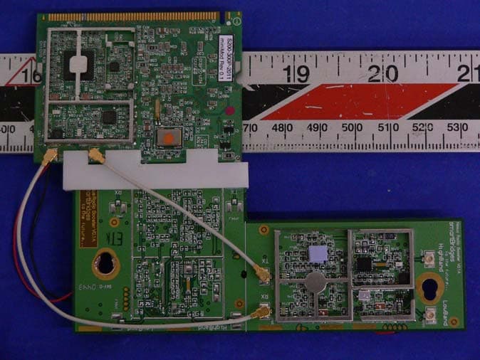
PWGNEXUS1
Apr 11, 2005IEEE 802.11a MiniPCI WLAN Card
Equipment Class
DTS - Digital Transmission System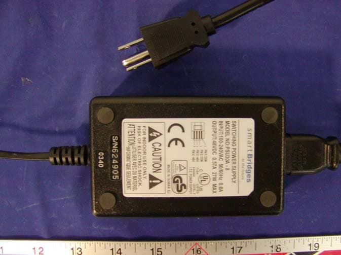
PWGSPEEDTRAP
Mar 16, 2004airPoint XO
Equipment Class
DTS - Digital Transmission System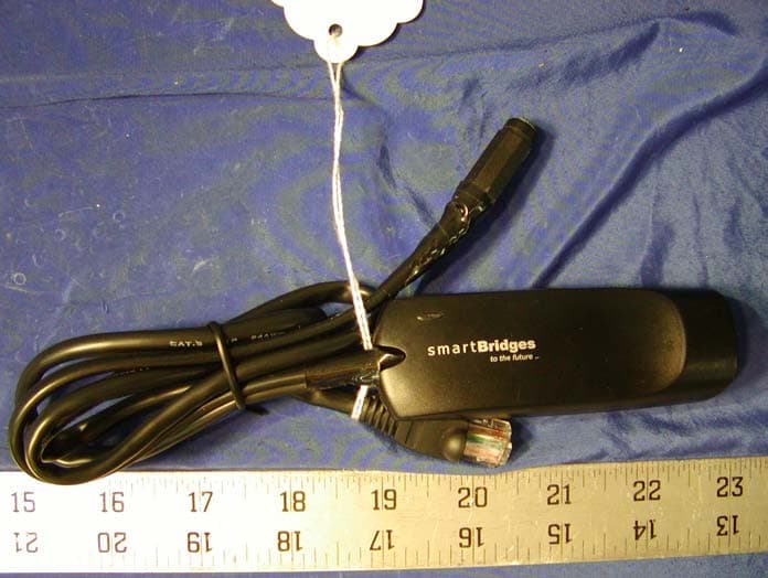
PWGAIRPOINTPRO
Apr 29, 2002Wireless AirPointPRO
Equipment Class
DSS - Part 15 Spread Spectrum Transmitter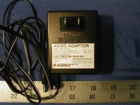
PWGDOLPHIN
Feb 20, 2002Wireless airPoint & airBridge
Equipment Class
DSS - Part 15 Spread Spectrum Transmitter