PYN22002AWireless Remote
ComSonics, Inc.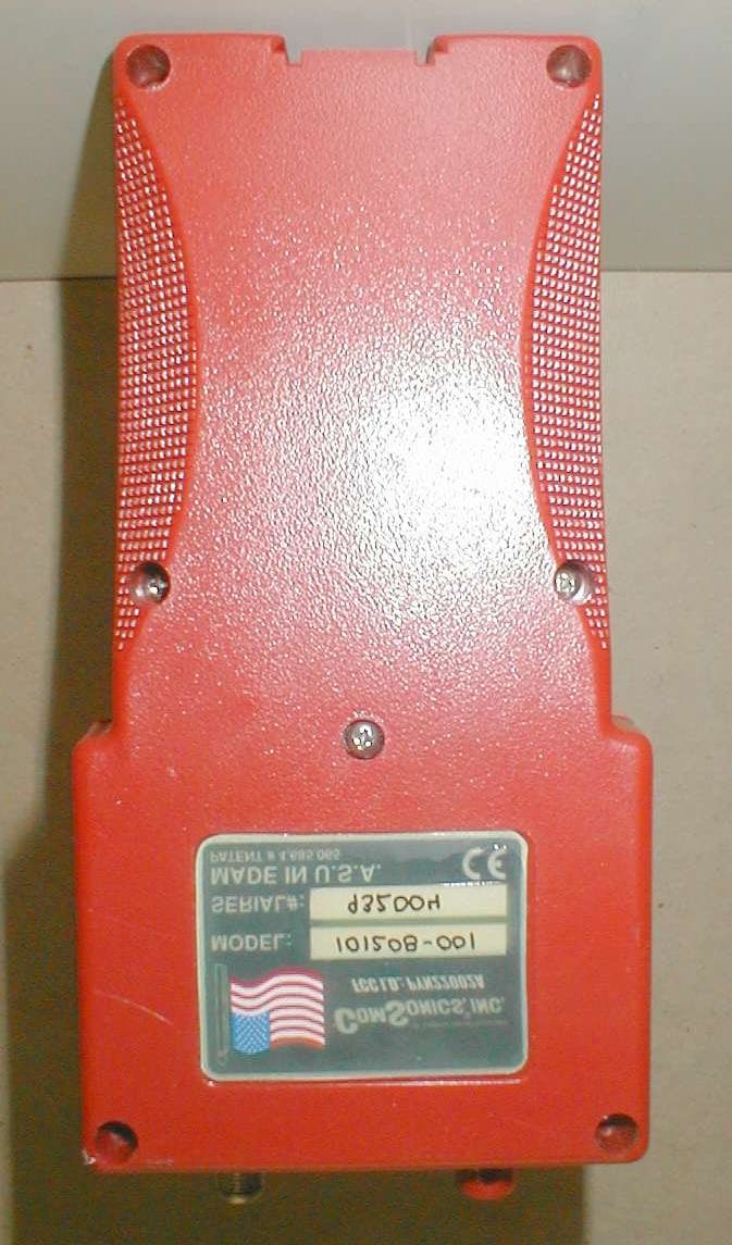
Click to zoom
Application Details
- Equipment Class
- DSC - Part 15 Security/Remote Control Transmitter
- Date of Grant
- Mar 26, 2002
- Application Purpose
- Original Equipment
- Date of Application
- Mar 26, 2002
- Equipment Note
- Wireless Remote
- Frequency Range
- 434.00000000 - 434.00000000
- Company
- ComSonics, Inc.
- Country
- United States
Documents & Files
Document Text
Text extracted from the exhibit documents filed with the FCC. Open a document above to read the original.
Users Manual
CSI Document 101xxx-001 Rev. A U U S S E E R R G G U U I I D D E E S UPPLEMENT TO W INDOW L ITE I NSTALLER 2 Warranty ComSonics, Inc. warrants this product to be free of material and workmanship defects for a period of one year from the original date of shipment. 3 Remedies provided under Warranty are exclusive and in lieu of all other warranties express or implied. The liability to ComSonics is limited to product repair or replacement at the discretion of ComSonics. ComSonics shall not be held liable for any incidental or consequential damages. The following are not covered by this warranty: 1) Parts or components not supplied by ComSonics, or parts or components that have been modified. 2) Any product or part failure that results from accident, abuse, misuse, neglect, or unauthorized repairs or modifications by individuals other than ComSonics personnel. 3) Failures caused by use of this product in extreme climates or moisture conditions. 4) CyberTek Qualifier Battery Pack Technical Support ComSonics maintains a Technical Support Service for customer convenience. Should the need arise, contact a Technical Support Representative by phone at 1-800-336-9681 or 1-540-434-5965; Fax at 1-540-432-9794; or Email at [email protected]. Return Information Products returned for repair, calibration, etc., must be safely packed. Please enclose information on the reason for return. Ship the material prepaid. All material in this manual is the property of ComSonics, Inc. and is protected under the United States copyright law. No material shall be reproduced or used in any form or by any means (graphic, electronic, or mechanical, including photocopying, recording, taping, or information storage and retrieval systems) without the written permission of: ComSonics, Inc. 1350 Port Republic Road Post Office Box 1106 Harrisonburg, Virginia 22801 USA Phone: (540) 434-5965 USA Toll Free: (800) 336-9681 Fax: (540) 434-9847 Email: [email protected] Internet: www.comsonics.com Agency Notice Changes or modifications not expressly approved by the manufacturer could void the user’s authority to operate the equipment. FCC ID: PYN12002A vehicle mounted device FCC ID: PYN22002A hand held device This device complies with Part 15 of the FCC Rules. Operation is subject to the following two conditions: (1) this device may not cause harmful interference, and (2) this device must accept any interference received, including interference that may cause undesired operation. CyberTek Qualifier and WindowLite are trademarks of ComSonics, Inc. 2001 ComSonics, Inc. All Rights Reserved Document No. 101xxx-001 Rev. A Qualifier Supplement Table of Contents Specifications......................................................................................................................... Supplemental Notice.............................................................................................................. System Overview................................................................................................................... Component Operation............................................................................................................ Transmitter................................................................................................................. Receiver ..................................................................................................................... Hardware Installation............................................................................................................. Theory of Operation .............................................................................................................. Transmitter Block Diagram ....................................................................................... Receiver Block Diagram............................................................................................ Qualifier Supplement 4 Qualifier Specifications Transmitter Power5 watts Frequency27.450, 27.470, or 27.490 MHz SizeTBD WeightTBD Storage Temperature-20°F ~ 150°F Operating Temperature0°F ~ 120°F Humidity5% ~ 95% (non condensing) Receiver Frequency27.450, 27.470, or 27.490 MHz Size7.7” x 3.5” x 2.3” Weight23 oz. Storage Temperature-20°F ~ 150°F Operating Temperature 0°F ~ 120°F HumidityWeather resistant Qualifier Supplement 1 Supplemental Notice This document contains the CyberTek Qualifier system functions and is supplemental to the WindowLite Installer User’s Guide, CSI Document 100673-003. System Overview ComSonics Qualifier is a multipart system that provides a means of identifying internal shielding integrity quality without having to enter the potential customer premises. One of Qualifier’s two transmitters, the Test Source Transmitter (TST) located within the service vehicle, provides an RF envelope that blankets the targeted premises. The second transmitter, the Test Key Transmitter (TKT) located within an optionally accessorized ComSonics’ Window Installer, delivers the signal that triggers the remotely located TST and sets up the Installer to receive traces of TST signal finding their way into the upstream path. With the Installer connected to either the premises grounding block or the associated drop at the housetap, a press of Installer’s “Q” button instructs TKT to trigger TST. When triggered by TKT, TST emits a brief, 5 watt pulse just above the CB radio band, and within the upstream spectrum at 27.45 MHz, 27.47 MHz or 27.49 MHz. TST then envelopes the premises with a signal of about +58 dBmV (assumes the service vehicle is about 75 feet from the premises). Shielding flaws within the in-home wiring invite the TST signal to infiltrate the upstream path. Once on the center conductor, the in-home wiring system funnels the TST signal to the Installer connection. The Installer measuring instrument takes a snapshot at precisely the right time to capture and readout that portion of the TST signal momentarily…
Text truncated - open the document above for the full version.
Block Diagram
ComSonics Inc. VCO 69.4 MHz-356.4 MHz PLL MC145156-1 P.S. / 128MC12018 CRYSTAL 4.00 MHz VARICAP CRYSTAL PULLER SWITCHED INDUCTOR I N 4 KHz STEPS +/- 50 Hz +12V QUALIFIER BPF 27.47 MHZ LPF 30 MHz POWER AMP Q1 ATTENUATOR VOLTAGE CONTROLLED Q20 AMP A1 RF AMP ERA-5 Q21 L.O. BUFFER MMBR5179 VOLTAGE CONTROLLED OSCILLATOR PHASE LOCKED LOOP U4 LMX1501AM VCXO 15.36 MHz VCXO 1 BPF 433.92 MHz SAW SAW DELAY LINE PULSE GENERATOR DETECTOR & LPF RX5000 ASH RECEIVER IC9 RF IN DATA OUT HPF Fc=300MHz HPF Fc=300MHz P1 U12 & U14RS232 TOTTL/CMOS INTERFACE MAX 232 ESE POWER SWITCH DB 9 ADJUSTABLE COMPARATOR ADJUSTABLE COMPARATOR P2 POWER POWERSWITCH MAIN U1A IRF7425 LEDS PWRXMIT VSWR TEMP SW2 ADDRESS SELECT ROTARY SWITCH CODED IC 1000 CLOCK DETECTOR 22.11684 MHz CRYSTAL Y2 GMSK UNREGULATED 13.8 V REF. I N FILTER DC OFFSET DC OFFSET CONTROL PROCESSOR AT89553-24JI U 11 433.92 MHz SENSOR VSWR 27 MHz COMPARATOR AMP BUFFER FILTER & CLOCK DATA CLOCK CLOCK DATA +13dB DRIVER +13dB P A D -10 dB +20dB -1 TO -55 dB 5 VOLT REGULATOR LM2931 U1 TEMP SENSOR IC6 LM234 LOG AMP U9 AD8307AD D TO A SETUP POWERRANGE U16 74HC138 LNA +26dB NF=1.7 dB SGA-4586 IC8
Cover Letter(s)
03/02/02 Mr. Greg Snyder In reference to FCC ID: PYN22002A Mr. Snyder Upon completion of review of the application for FCC ID: PYN22002A, there are several issues that must be addressed before the application can be granted by ATCB. Please address each issue below. 1) Please provide a legible copy of the Theory of Operation – the copy provided is extremely hard to read. R. Please see exhibit “Improved Theory of Operation.pdf” 2) The 731 form states this is a 15.231 device operating at 434 MHz, the theory of operation appears to state that this device is for data transmission. In accordance with devices operating under the provisions of 15.231 (a), these devices are prohibited from sending any type of data other then recognition codes. Please explain how this device meets the 15.231(a) rules. R. The unit only transmits a control signal at 434 MHz to the 27MHz transmitter device (separate certification) which is located on a utility truck/van. 3) The system appears to be possibly a composite system with receiver and digital portion, please provide a copy of the Declaration of Conformity for this system or a set of test data for the report of this if this is correct. R. The hand-held 434 MHz unit only has digital circuitry that is associated with its operation and is to be certified as a single unit with one FCC ID. 4) Reviewing the user manual – there are several questions that arise. R. The following description should address the questions A through H. The 434 MHz handheld unit is to be certified as a single unit under FCC ID: PYN22002A. This unit only contains digital circuitry and the circuitry for the 434 MHz transmitter control signal. The 434 MHz receiver is located in a separate box which also contains a 27 MHz transmitter. This device, which is located in a vehicle (typically a utility truck or construction type van) will be separately certified (FCC ID: PYN12002A). The handheld unit (FCC ID: PYN22002A) contains an “F” type coaxial connector which connects directly to a 75 ohm coax cable at the entrance of a house or at the local tap. The user’s guide that was uploaded with the application refers to the handheld unit as the “receiver” or “Qualifier Receiver”. Page 13 shows a block diagram of the “receiver” which contains the 434 MHz transmitter. The term “receiver” within the manual is only used here as it refers to the operation of the overall system in terms of the integrity measurements the system is performing. A preliminary product literature has been uploaded to help depict the overall function of the system. A) The manual describes a composite system consisting of two transmitters and a receiver. These devices should be certified together either under one FC ID or if as separate packages you need to modify your 731 for question 7b and answer yes to question (b) since according to the manual it is marketed or used together. R. Separate units. B) The manual makes no reference at all to the 434 MHz transmitter or operating parameters of it, is this the correct manual? R. This is the correct manual which will be supplied for the system. C) The manual describes a 27 MHz 5 W transmitter. Is this the vehicle mounted system PYN12002A or something different? R. This is the separate vehicle mounted unit and different application. D) The 27 MHz transmitter operating at 5W would require certification under Part 90 of the rules, the application is for a 434 MHz transmitter under Part 15, Please verify this is an application for a Part 15 .231 operating at 434 MHz transmitter only? R. Yes, this application applies only to the Part 15.231 unit. E) Please verify that there is not a 27MHz transmitter in the handheld unit. If this is so, then this a co-located transmitter and cannot be certified by a TCB per the exclusion list. R. The handheld unit does not contain the 27 MHz transmitter. F) Is there a 27 MHz receiver in this unit? R. No. G) There appears to be an external antenna connection on this device, please provide information or a statement that the antenna connection is for the receiver portion only. R. This connector is an “F”-type connector for direct connection to the 75 ohm coaxial cable of the house under test. H) Please provide a copy of the FCC warnings in the manual about unauthorized modifications R. Please see Page 2 of the “Qualifier Prelim User Guide.pdf” under the heading “Agency Notice”. Regards David A. Case NCE Examining Engineer mailto:[email protected] The items indicated above must be submitted before processing can continue on the above referenced application. Failure to provide the requested information may result in application termination. Correspondence should be considered part of the permanent submission and may be viewed from the Internet after a Grant of Equipment Authorization is issued. Please do not respond to this correspondence using the email reply button. In order for your response to be processed expeditiously, you must submit your documents through the AmericanTCB.com website. Also, please note that partial responses increase processing time and should not be submitted. Any questions about the content of this correspondence should be directed to the sender.
Cover Letter(s)
November 29, 2001 American Telecommunications Certification Body, Inc. 6731 Whittier Avenue Suite C110 McLean, VA 22101 To Whom It May Concern: Please be advised that ComSonics, Inc. authorizes Washington Laboratories, Ltd. to act on our behalf, until otherwise notified, for applications submitted to American Telecommunications Certification Body, Inc. (ATCB). We certify that we are not subject to denial of federal benefits, that includes FCC benefits, pursuant to Section 5301 of the Anti-Drug Abuse Act of 1988, U.S.C. 862. Further, no party, as defined in 47 CFR 1.2002(b), to the application is subject to denial of federal benefits, that includes FCC benefits. Thank you for your attention to this matter. Richard L. Shimp Chief of New Technology ComSonics, Inc.
External Photos
Front View Back View Side View Top View Bottom View
Internal Photos
Housing Open Inside Top Cover Inside Bottom Cover Top View Main Assembly Including Transmitter Module Transmitter Module Top View Transmitter Module Bottom View Top View- Shield 1 and LCD Module Removed Shield 2 Removed Shield 3 Removed Shield 3 and Phillips Module Top Shield Removed Phillips Module Shifted Up Phillips Module Bottom View, Shield Removed
Test Report
Document 6879-01, Rev. 0 FCC Certification Test Report Washington Laboratories, Ltd February 2002 FCC Certification Test Report for ComSonics, Inc. PYN22002A February 27, 2002 Prepared for: ComSonics, Inc. 1350 Port Republic Road Harrisonburg, VA 22801 Prepared By: Washington Laboratories, Ltd. 7560 Lindbergh Drive Gaithersburg, Maryland 20879 FCC Certification Test Report Document 6879-01, Rev. 0 FCC Certification Test Report Washington Laboratories, Ltd February 2002 FCC Certification Test Program FCC Certification Test Report for the ComSonics, Inc. 433 MHz Qualifier PYN22002A February 27, 2002 WLL JOB# 6879 Prepared by: Brian J. Dettling Documentation Specialist Reviewed by: Gregory M. Snyder Chief EMC Engineer Document 6879-01, Rev. 0 FCC ID: PYN2202A FCC Certification Test Report Washington Laboratories, Ltd February 2002 ii Abstract This report has been prepared on behalf of ComSonics, Inc. to support the attached Application for Equipment Authorization. The test report and application are submitted for a periodic intentional radiator under Part 15.231 of the FCC Rules and Regulations. This Federal Communication Commission (FCC) Certification Test Report documents the test configuration and test results for a ComSonics, Inc. 433 MHz Qualifier. Testing was performed on an Open Area Test Site (OATS) of Washington Laboratories, Ltd, 7560 Lindbergh Drive, Gaithersburg, MD 20879. Site description and site attenuation data have been placed on file with the FCC's Sampling and Measurements Branch at the FCC laboratory in Columbia, MD. Washington Laboratories, Ltd. has been accepted by the FCC and approved by NIST NVLAP (NVLAP Lab Code: 200066-0) as an independent FCC test laboratory. The ComSonics, Inc. 433 MHz Qualifier complies with the limits for a periodic intentional radiator device under Part 15.231 of the FCC Rules and Regulations. Document 6879-01, Rev. 0 FCC ID: PYN2202A FCC Certification Test Report Washington Laboratories, Ltd February 2002 iii Table of Contents Abstract......................................................................................................ii 1 Introduction...................................................................................................................1 1.1 Compliance Statement............................................................................................1 1.2 Test Scope............................................................................................................1 1.3 Contract Information..............................................................................................1 1.4 Test Dates.............................................................................................................1 1.5 Test and Support Personnel....................................................................................1 1.6 Abbreviations.........................................................................................................2 2 Equipment Under Test....................................................................................................3 2.1 EUT Identification & Description............................................................................3 2.2 Test Configuration..................................................................................................3 2.3 Testing Algorithm...................................................................................................3 2.4 Test Location.........................................................................................................4 2.5 Measurements........................................................................................................4 2.5.1 References.....................................................................................................4 2.6 Measurement Uncertainty.......................................................................................4 3 Test Equipment..............................................................................................................5 4 Test Results...................................................................................................................5 4.1 Duty Cycle Correction...........................................................................................5 4.2 RF Power Output: (FCC Part §2.1046)...............................................................12 4.3 Modulation Characteristics: (FCC Part §2.1047); Audio Frequency Response......12 4.4 Occupied Bandwidth: (FCC Part §2.1049)..........................................................12 4.5 Spurious Emissions at Antenna Terminals (FCC Part §2.1051...............................14 4.6 Radiated Spurious Emissions: (FCC Part §2.1053)...............................................14 4.6.1 Test Procedure............................................................................................14 4.7 Frequency Stability: (FCC Part §2.1055).............................................................18 5 Transmitter Environmental Assessment, Maximum Permissible Exposure (MPE)............18 Document 6879-01, Rev. 0 FCC ID: PYN2202A FCC Certification Test Report Washington Laboratories, Ltd February 2002 iv List of Tables Table 1. Device Summary....................................................................................................3 Table 2: Test Equipment List...............................................................................................5 Table 3. Duty Cycle Correction..........................................................................................12 Table 4. Occupied Bandwidth Results................................................................................14 Table 5. Radiated Spurious Emissions Limits.......................................................................14 Table 6: Radiated Emission Test Data................................................................................15 List of Figures Figure…
Text truncated - open the document above for the full version.
Test Setup Photos
Radiated Emissions Test Setup
Contact Information
Applicant
Richard L Shimp(Chief of Technology)
Technical Contact
Washington LabsGreg Snyder
[email protected]301 417 0220
7560 Lindbergh Drive · Gaithersburg, Maryland · United States
Non-Technical Contact
Washington LabsBrian Dettling
[email protected]310 417 0220
Test Firm
Washington Laboratories, Ltd.Michael Violette
Technical Specifications
| # | Rule Parts | Frequency Range | Power Output |
|---|---|---|---|
| 1 | 15.231 | 434 MHz - 434 MHz | - |
Other Applications from ComSonics, Inc.
PYN2007VMD
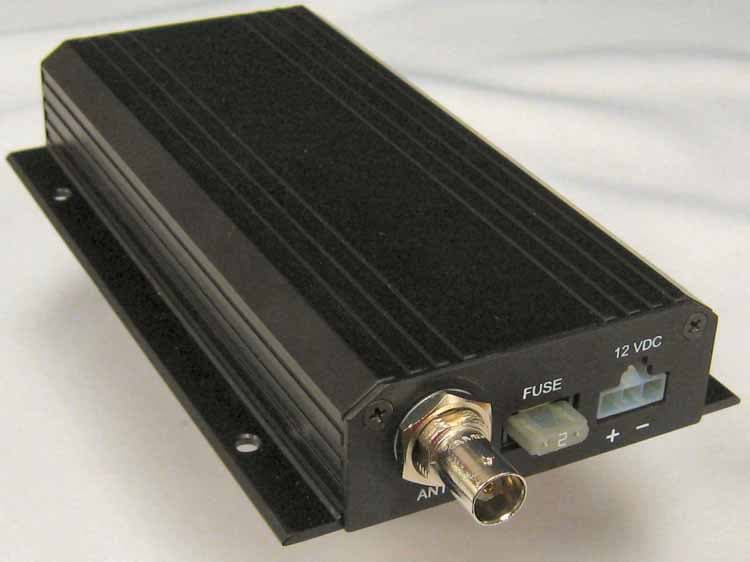
Mar 20, 2008Vehicle Mounted Transmitter
Equipment Class
TNB - Licensed Non-Broadcast Station Transmitter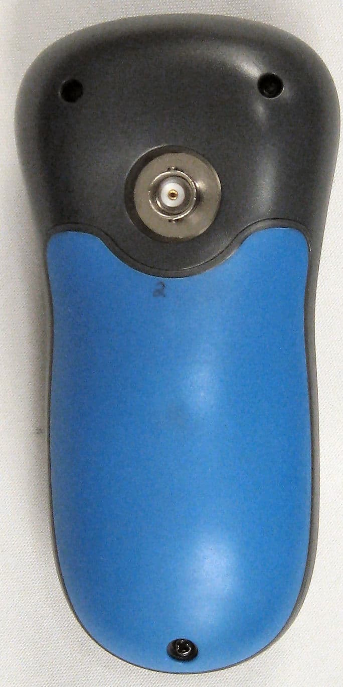
PYN2007HHD
Sep 09, 2007Remote Control Device
Equipment Class
DSC - Part 15 Security/Remote Control Transmitter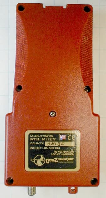
PYN22002B
Dec 09, 2002Home Qualification System
Equipment Class
DSC - Part 15 Security/Remote Control Transmitter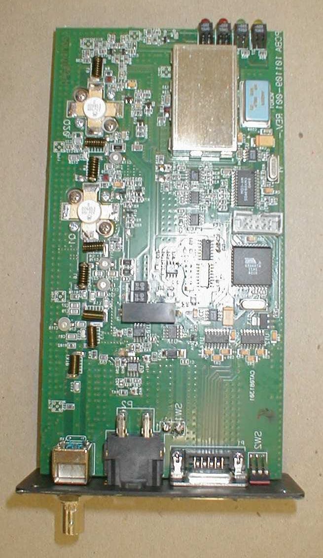
PYN12002A
Aug 11, 2002Licensed Transmitter
Equipment Class
TNB - Licensed Non-Broadcast Station Transmitter