PYN22002BHome Qualification System
ComSonics, Inc.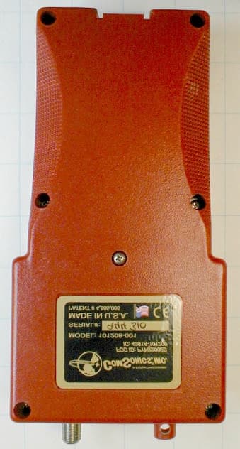
Click to zoom
Application Details
- Equipment Class
- DSC - Part 15 Security/Remote Control Transmitter
- Date of Grant
- Dec 09, 2002
- Application Purpose
- Original Equipment
- Date of Application
- Dec 09, 2002
- Equipment Note
- Home Qualification System
- Frequency Range
- 434.00000000 - 434.00000000
- Company
- ComSonics, Inc.
- Country
- United States
Documents & Files
Document Text
Text extracted from the exhibit documents filed with the FCC. Open a document above to read the original.
Users Manual
??? NEED HELP ??? APPLYING FOR YOUR QUALIFIER TRANSMITTER LICENSE We have included on the Feature Installation Software CD a folder full of instructions, application templates in Microsoft Word and Acrobat formats along with helpful web sites to get you up and running in no time. Please browse to and open the file named Customer Packet. Read the Adobe Acrobat document Read Me First. If you encounter difficulty, please give our Customer Service Representatives a call. They will be glad to help. 1-800-336-9681 CSI Document 101268-001 Rev. C unreleased H H O O M M E E Q Q U U A A L L I I F F I I C C A A T T I I O O N N S S Y Y S S T T E E M M U U s s e e r r G G u u i i d d e e Signal Level Meter with Digital Level Capability and Home Qualification Features Warranty ComSonics, Inc. warrants this product to be free of material and workmanship defects for a period of one year from the original date of shipment. Remedies provided under Warranty are exclusive and in lieu of all other warranties express or implied. The liability to ComSonics is limited to product repair or replacement at the discretion of ComSonics. ComSonics shall not be held liable for any incidental or consequential damages. The following are not covered by this warranty: 1) Parts or components not supplied by ComSonics, or parts or components that have been modified. 2) Any product or part failure that results from accident, abuse, misuse, neglect, or unauthorized repairs or modifications by individuals other than ComSonics personnel. 3) Failures caused by use of this product in extreme climates or moisture conditions. 4) CyberTek Qualifier Battery Pack Technical Support ComSonics maintains a Technical Support Service for customer convenience. Should the need arise, contact a Technical Support Representative by telephone at 1-800-336-9681 or 1-540-434-5965; Fax at 1-540-432-9794; or Email at [email protected]. Return Information Products returned for repair, calibration, etc. must be safely packed. Please enclose information on the reason for return. Ship the material prepaid. All material in this manual is the property of ComSonics, Inc. and is protected under the United States copyright law. No material shall be reproduced or used in any form or by any means (graphic, electronic, or mechanical, including photocopying, recording, taping, or information storage and retrieval systems) without the written permission of: ComSonics, Inc. 1350 Port Republic Road Post Office Box 1106 Harrisonburg, Virginia 22801 USA Phone: (540) 434-5965 USA Toll Free: (800) 336-9681 Fax: (540) 434-9847 Email: [email protected] Internet: www.comsonics.com Agency Notice Changes or modifications not expressly approved by the manufacturer could void the user’s authority to operate the equipment. FCC ID: PYN12002A vehicle mounted device FCC ID: PYN22002B hand held device This device complies with Part 15 of the FCC Rules. Operation is subject to the following two conditions: (1) this device may not cause harmful interference, and (2) this device must accept any interference received, including interference that may cause undesired operation. This Class B digital apparatus complies with Canadian ICES-003. Cet appareil numérique de la Classe B est conforme à la norme NMB-003 du Canada. CyberTek Qualifier and WindowLite are trademarks of ComSonics, Inc. 2002 ComSonics, Inc. All Rights Reserved Document No. 101268-001 Rev. C unreleased Qualifier System i Table of Contents - Signal Level Meter and Home Qualification System Specifications .................................................................................................................... iii Description ...................................................................................................................... 1-1 Battery Care .................................................................................................................... 1-2 Power-Up ........................................................................................................................ 1-3 User Preferences ............................................................................................................. 1-4 Country Set Define .................................................................................................. 1-5 Units of Measure Define .......................................................................................... 1-6 Quick-Tune Channels Define .................................................................................. 1-7 Making Measurements .................................................................................................... 1-8 Backlight ....................................................................................................................... 1-11 Home Qualification System - Overview ......................................................................... 2-1 Hardware Installation ...................................................................................................... 2-2 System Operation ............................................................................................................ 2-8 Qualifier Transmitter Details ................................................................................... 2-8 Qualifier Meter Details ............................................................................................ 2-9 Appendix A: Keypress Reference .................................................................................. 3-1 Appendix B: Channel Line-Up Set and Country Set Codes ........................................... 3-2 Appendix C: Feature Installation Utility ........................................................................ 3-3 Appendix D: Pressure Relief .......................................................................................... 3-6 Appendix E: Battery Replacement .................................................................…
Text truncated - open the document above for the full version.
Block Diagram
3 Transmitter Theory of Operation Introduction RFM’s TX-series hybrid transmitters are specifically designed for short-range wireless data communication applications. The trans - mitters provide robust operation, very small size, low power con - sumption and low implementation cost. All critical RF functions are contained in the hybrid, simplifying and speeding design-in. The transmitters can be readily configured to support a wide range of data rates and protocol requirements. TX-series transmitters feature excellent suppression of output harmonics and virtually no other RF emissions, making them easy to certify to short- range (unlicensed) radio regulations. Transmitter Block Diagram Figure 1 is the general block diagram of the transmitter. Please refer to Figure 1 for the following discussions. Antenna Port The only external RF components needed for the transmitter are the antenna and its matching components. Antennas presenting an im - pedance in the range of 35 to 72 ohms resistive can be satisfactorily matched to the RFIO pin with a series matching coil and a shunt matching/ESD protection coil. Other antenna impedances can be matched using two or three components. For some impedances, two inductors and capacitor will be required. A DC path from RFIO to ground is required for ESD protection. Transmitter Chain The transmitter chain consists of a SAW coupled-resonator oscilla - tor followed by a modulated buffer amplifier. The SAW coupled res - onator output filter suppresses transmitter harmonics to the antenna. Transmitter operation supports two modulation formats, on-off keyed (OOK) modulation, and amplitude-shift keyed (ASK) modula - tion. When OOK modulation is chosen, the transmitter output turns completely off between “1” data pulses. When ASK modulation is chosen, a “1” pulse is represented by a higher transmitted power level, and a “0” is represented by a lower transmitted power level. OOK modulation provides compatibility with first-generation ASH technology, and provides for power conservation. ASK modulation must be used for high data rates (data pulses less than 200 μs). ASK modulation also reduces the effects of some types of interfer - ence and allows the transmitted pulses to be shaped to control mod - ulation bandwidth. The modulation format is chosen by the state of the CNTRL0 and the CNTRL1 mode control pins, as discussed below. In the OOK mode, the oscillator amplifier TXA1 and buffer amplifier TXA2 are turned off when the voltage to the TXMOD input falls below 220 mV. In the OOK mode, the data rate is limited by the 40 μs turn-on and turn-off time of the oscillator. In the ASK mode TXA1 is biased ON continuously, and the output of TXA2 is modulated by the TXMOD input current. Minimum output power occurs in the ASK mode when the modulation driver sinks about 10 μA of current from the TXMOD pin. Transmitter Block Diagram TXA1TXA2 Antenna SAW Coupled Resonator SAW CR Filter Modulation & Bias Control TX IN CN TRL1 CN TRL0 Tune/ESD Ant Tune R TXM Figure 1
Cover Letter(s)
American Telecommunications Certification Body, Inc. 6731 Whittier Avenue Suite C110 McLean, VA 22101 To Whom It May Concern: Please be advised that ComSonics, Inc. authorizes Washington Laboratories, Ltd. to act on our behalf, until otherwise notified, for applications submitted to American Telecommunications Certification Body, Inc. (ATCB). We certify that we are not subject to denial of federal benefits, that includes FCC benefits, pursuant to Section 5301 of the Anti-Drug Abuse Act of 1988, U.S.C. 862. Further, no party, as defined in 47 CFR 1.2002(b), to the application is subject to denial of federal benefits, that includes FCC benefits. Thank you for your attention to this matter. Richard L. Shimp Chief of New Technology ComSonics, Inc.
Cover Letter(s)
American Telecommunications Certification Body Inc. 6731 Whittier Ave, McLean, VA 22101 November 29, 2002 RE: FCC ID: PYN22002B Attention: Gregory M. Snyder / Brian J. Dettling I have a few comments on this Application. 1 Please provide information on how the label is permanently affixed to the product. The label location file is not readable enough to determine if this information is present. 2 Please note that 15.231 devices CANNOT transmit data. This is strictly forbidden. Also please note that the operational description for this device specifically states that this unit transmits data (it states, RFM’s TX-series hybrid transmitters are specifically designed for short-range wireless data communication applications.”) The device is not certifiable under these conditions. Please correct all documentation to clearly state the intent of this device. Is it to transmit control codes to a separate device, or other purposes? Is it in a composite device? Has application for certification been done for the other part of the composite device? How does this fit a 15.231a device? If there are two separate transmitters in this system you must CLEARLY describe each specific transmitter and how it functions. This description cannot be ambiguous or confusing. 3 Please provide evidence that the antenna used with this device meets the antenna requirements for Part 15 devices. The theory of operation states that other antenna(s) can be used with this device. What antenna is it talking about, the 15.231 device or the 27MHz licensed device? Please note that no antenna can be used in a 15.231 device that has not been tested with this device. Please make this clear in the report and operational description. 4 Please note that other than a one or two sentence (very ambiguous) statement about the 15.231 device, the manual does not describe this unit. Please explain in your manual how this 15.231 unit fits into the system. 5 Please explain how this device meets the manual / automatic shut off time requirement of 15.231. 6 Please note, the manual does not appear to have any of the Part 15 required statements. Please provide a manual with the appropriate 15.19, 15.21 statements. 7 Please note that the device and label appear sufficiently large to contain the required 15.19 2- condition statement on the device. Please provide a label with this 2-condition statement. Please note that the exception in 15.19(a)(5) does not appear to apply to this device. 8 Please note, the report calls this a PYN-2202B, the label and 731 call this a PYN22002B. Please make documentation reflect the correct ID number. Dennis Ward mailto:[email protected] The items indicated above must be submitted before processing can continue on the above referenced application. Failure to provide the requested information may result in application termination. Correspondence should be considered part of the permanent submission and may be viewed from the Internet after a Grant of Equipment Authorization is issued. Please do not respond to this correspondence using the email reply button. In order for your response to be processed expeditiously, you must submit your documents through the AmericanTCB.com website. Also, please note that partial responses increase processing time and should not be submitted. Any questions about the content of this correspondence should be directed to the sender.
External Photos
Top View Bottom View Side View Top Bottom
Internal Photos
Disassembled Tx Module Removed Tx Module Top Tx Module Bottom Function Module Details
Operational Description
3 Transmitter Theory of Operation Introduction RFM’s TX-series hybrid transmitters are specifically designed for short-range wireless data communication applications. The trans - mitters provide robust operation, very small size, low power con - sumption and low implementation cost. All critical RF functions are contained in the hybrid, simplifying and speeding design-in. The transmitters can be readily configured to support a wide range of data rates and protocol requirements. TX-series transmitters feature excellent suppression of output harmonics and virtually no other RF emissions, making them easy to certify to short- range (unlicensed) radio regulations. Transmitter Block Diagram Figure 1 is the general block diagram of the transmitter. Please refer to Figure 1 for the following discussions. Antenna Port The only external RF components needed for the transmitter are the antenna and its matching components. Antennas presenting an im - pedance in the range of 35 to 72 ohms resistive can be satisfactorily matched to the RFIO pin with a series matching coil and a shunt matching/ESD protection coil. Other antenna impedances can be matched using two or three components. For some impedances, two inductors and capacitor will be required. A DC path from RFIO to ground is required for ESD protection. Transmitter Chain The transmitter chain consists of a SAW coupled-resonator oscilla - tor followed by a modulated buffer amplifier. The SAW coupled res - onator output filter suppresses transmitter harmonics to the antenna. Transmitter operation supports two modulation formats, on-off keyed (OOK) modulation, and amplitude-shift keyed (ASK) modula - tion. When OOK modulation is chosen, the transmitter output turns completely off between “1” data pulses. When ASK modulation is chosen, a “1” pulse is represented by a higher transmitted power level, and a “0” is represented by a lower transmitted power level. OOK modulation provides compatibility with first-generation ASH technology, and provides for power conservation. ASK modulation must be used for high data rates (data pulses less than 200 μs). ASK modulation also reduces the effects of some types of interfer - ence and allows the transmitted pulses to be shaped to control mod - ulation bandwidth. The modulation format is chosen by the state of the CNTRL0 and the CNTRL1 mode control pins, as discussed below. In the OOK mode, the oscillator amplifier TXA1 and buffer amplifier TXA2 are turned off when the voltage to the TXMOD input falls below 220 mV. In the OOK mode, the data rate is limited by the 40 μs turn-on and turn-off time of the oscillator. In the ASK mode TXA1 is biased ON continuously, and the output of TXA2 is modulated by the TXMOD input current. Minimum output power occurs in the ASK mode when the modulation driver sinks about 10 μA of current from the TXMOD pin. Transmitter Block Diagram TXA1TXA2 Antenna SAW Coupled Resonator SAW CR Filter Modulation & Bias Control TX IN CN TRL1 CN TRL0 Tune/ESD Ant Tune R TXM Figure 1 4 The transmitter RF output power is proportional to the input current to the TXMOD pin. A series resistor is used to adjust the peak trans - mitter output power. Maximum saturated output power requires 450 μA of input current. Transmitter Mode Control The three transmitter operating modes – transmit ASK, transmit OOK, and power-down (sleep), are controlled by the Modulation & Bias Control function, and are selected with the CNTRL1 and CNTRL0 control pins. Setting CNTRL1 high and CNTRL0 low place the unit in the ASK transmit mode. Setting CNTRL1 low and CNTRL0 high place the unit in the OOK transmit mode. Setting CNTRL1 and CNTRL0 both low place the unit in the power-down mode. (Note that the resistor driving TXMOD must also be low in the power-down mode to minimize power-down current.) CNTRL1 and CNTRL0 are CMOS compatible inputs. These inputs must be held at a logic level; they cannot be left unconnected. Turn-On Timing The maximum time required for either the OOK or ASK transmitter mode to become operational is 5 ms after the supply voltage reaches 2.7 Vdc. The total turn-on time to stable transmitter opera - tion for a 10 ms power supply rise time is 15 ms. Sleep and Wake-Up Timing The maximum transition time from either transmit mode to the sleep mode (t TOS and t TAS ) is 40 μs after CNTRL1 and CNTRL0 are both low (1 μs fall time). The maximum time required to switch from the sleep mode to either transmit mode (t STO and t STA ) is 46 μs. Most of this time is due to the start-up of the transmitter oscillator. SM-20L Case Drawing 0.08" (2.03) 0.02" (0.51) 0.04" (1.02) 0.44" (11.2) 0.39" (9.91) 0.13" (3.30) 0.13" (3.30) 3 4 5 6 7 9 11 12 13 14 15 16 17 19 Transmitter Pin Out RFIO 8 2 10 201 18 NC NC NC NC NC NC NC NC TXMODNC NC NC GND1 VCC1 GND2 VCC2 GND3 CNTRL0 CNTRL1 0.000 0.000 .140 .270 .410 .0775 .1025 .1175 .1575 .1975 .2375 .2775 .3175 .3575 .3825 .4600 .1975 .1725 .2125.2375 Dimensions in inches SM-20L PCB Pad Layout
Test Report
Document 7276-01, Rev. 1 FCC ID: PYN22002B FCC Certification Test Report Washington Laboratories, Ltd November 2002 FCC Certification Test Report for ComSonics, Inc. PYN22002B November 22, 2002 Prepared for: ComSonics, Inc. 1350 Port Republic Road Harrisonburg, VA 22801 Prepared By: Washington Laboratories, Ltd. 7560 Lindbergh Drive Gaithersburg, Maryland 20879 FCC Certification Test Report Document 7276-01, Rev. 1 FCC ID: PYN22002B FCC Certification Test Report Washington Laboratories, Ltd November 2002 FCC Certification Test Program FCC Certification Test Report for the ComSonics, Inc. 101208-001 Qualifier PYN22002B November 22, 2002 WLL JOB# 7276 Prepared by: Brian J. Dettling Documentation Specialist Reviewed by: Michael Violette President Document 7276-01, Rev. 1 FCC ID: PYN22002B FCC Certification Test Report Washington Laboratories, Ltd November 2002 ii Abstract This report has been prepared on behalf of ComSonics, Inc. to support the attached Application for Equipment Authorization. The test report and application are submitted for a Periodic Intentional Radiator under Part 15.231 of the FCC Rules and Regulations. This Federal Communication Commission (FCC) Certification Test Report documents the test configuration and test results for a ComSonics, Inc. 101208-001 Qualifier. Testing was performed on an Open Area Test Site (OATS) of Washington Laboratories, Ltd, 7560 Lindbergh Drive, Gaithersburg, MD 20879. Site description and site attenuation data have been placed on file with the FCC's Sampling and Measurements Branch at the FCC laboratory in Columbia, MD. Washington Laboratories, Ltd. has been accepted by the FCC and approved by NIST NVLAP (NVLAP Lab Code: 200066-0) as an independent FCC test laboratory. The ComSonics, Inc. 101208-001 Qualifier complies with the limits for a Periodic Intentional Radiator device under Part 15.231 of the FCC Rules and Regulations. Document 7276-01, Rev. 1 FCC ID: PYN22002B FCC Certification Test Report Washington Laboratories, Ltd November 2002 iii Table of Contents Abstract......................................................................................................ii 1 Introduction...................................................................................................................1 1.1 Compliance Statement............................................................................................1 1.2 Test Scope............................................................................................................1 1.3 Contract Information..............................................................................................1 1.4 Test Dates.............................................................................................................1 1.5 Test and Support Personnel....................................................................................1 1.6 Abbreviations.........................................................................................................2 2 Equipment Under Test....................................................................................................3 2.1 EUT Identification & Description............................................................................3 2.2 Test Configuration..................................................................................................3 2.3 Testing Algorithm...................................................................................................4 2.4 Test Location.........................................................................................................4 2.5 Measurements........................................................................................................4 2.5.1 References.....................................................................................................4 2.6 Measurement Uncertainty.......................................................................................4 3 Test Equipment..............................................................................................................5 4 Test Results...................................................................................................................6 4.1 Duty Cycle Correction...........................................................................................6 4.2 RF Power Output: (FCC Part §2.1046)...............................................................12 4.3 Modulation Characteristics: (FCC Part §2.1047); Audio Frequency Response......12 4.4 Occupied Bandwidth: (FCC Part §2.1049)..........................................................12 4.5 Spurious Emissions at Antenna Terminals (FCC Part §2.1051...............................14 4.6 Radiated Spurious Emissions: (FCC Part §2.1053)...............................................14 4.6.1 Test Procedure..........................................................................................14 4.7 Frequency Stability: (FCC Part §2.1055).............................................................17 Document 7276-01, Rev. 1 FCC ID: PYN22002B FCC Certification Test Report Washington Laboratories, Ltd November 2002 iv List of Tables Table 1. Device Summary....................................................................................................3 Table 2: Test Equipment List...............................................................................................5 Table 3. Duty Cycle Correction..........................................................................................12 Table 4. Occupied Bandwidth Results................................................................................14 Table 5. Radiated Spurious Emissions Limits.......................................................................14 Table 6: Radiated Emission Test Data................................................................................15 List of Figures Figure 1. Duty Cycle Plot, Worst-Case......................…
Text truncated - open the document above for the full version.
Test Setup Photos
Radiated Emissions Test Setup
Contact Information
Applicant
Richard L Shimp(Chief of Technology)
Technical Contact
Washington Laboratories, Ltd.Gregory M Snyder
[email protected]301/ 417-0220
7560 Lindbergh Drive · Gaithersburg, Maryland · United States
Non-Technical Contact
Washington Laboratories, Ltd.Brian J Dettling
[email protected]301/ 417-0220
Test Firm
Washington Laboratories, Ltd.Michael Violette
Technical Specifications
| # | Rule Parts | Frequency Range | Power Output |
|---|---|---|---|
| 1 | 15.231 | 434 MHz - 434 MHz | - |
Other Applications from ComSonics, Inc.
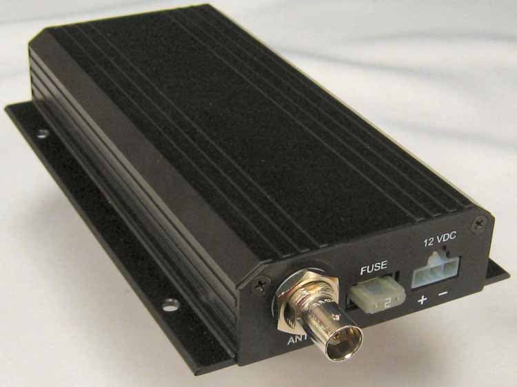
PYN2007VMD
Mar 20, 2008Vehicle Mounted Transmitter
Equipment Class
TNB - Licensed Non-Broadcast Station Transmitter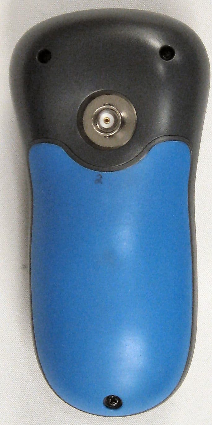
PYN2007HHD
Sep 09, 2007Remote Control Device
Equipment Class
DSC - Part 15 Security/Remote Control Transmitter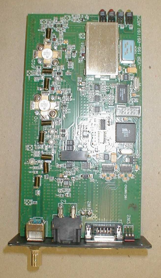
PYN12002A
Aug 11, 2002Licensed Transmitter
Equipment Class
TNB - Licensed Non-Broadcast Station Transmitter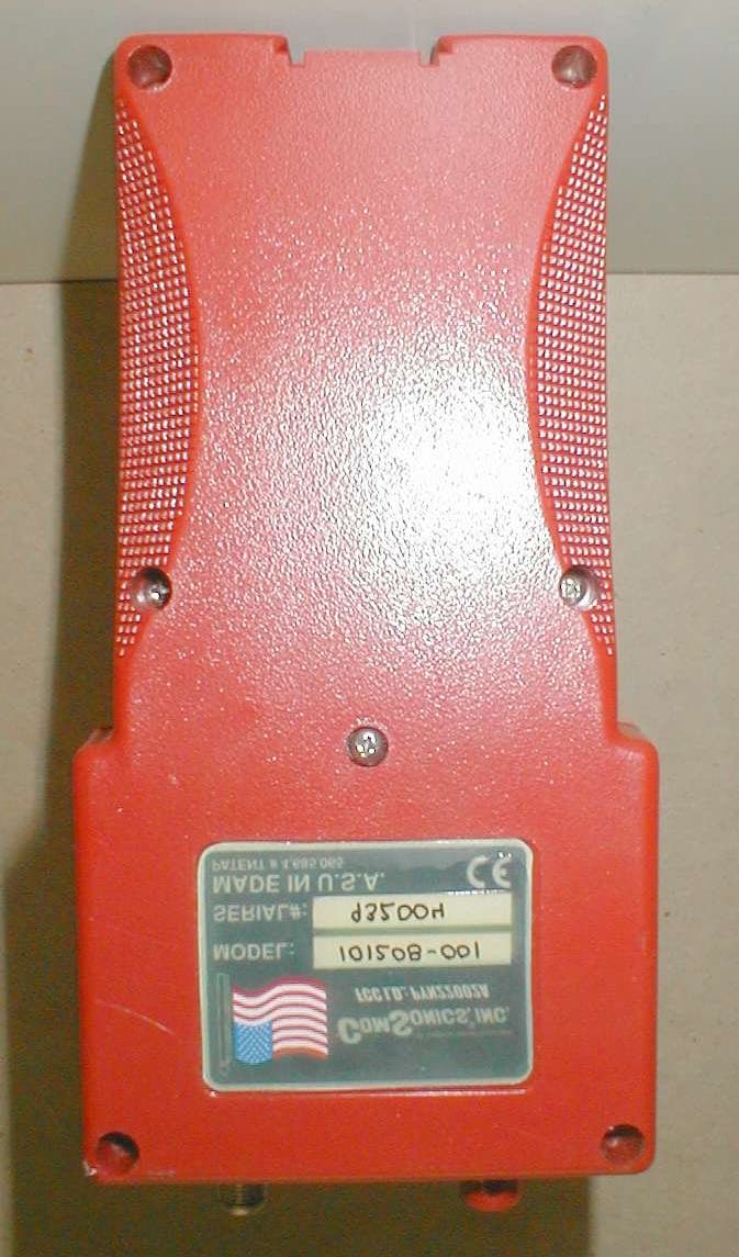
PYN22002A
Mar 26, 2002Wireless Remote
Equipment Class
DSC - Part 15 Security/Remote Control Transmitter