Q3HBS2035-0Exciter
AeroScout
Click to zoom
Application Details
- Equipment Class
- DCD - Part 15 Low Power Transmitter Below 1705 kHz
- Date of Grant
- Nov 23, 2004
- Application Purpose
- Original Equipment
- Date of Application
- Nov 23, 2004
- Equipment Note
- Exciter
- Frequency Range
- 0.12500000 - 0.12500000
- Company
- AeroScout
- Country
- Israel
Documents & Files
Document Text
Text extracted from the exhibit documents filed with the FCC. Open a document above to read the original.
Users Manual
AeroScout Exciter Version 1.0 User’s Manual Disclaimer The information and know-how included in this document are the exclusive property of AeroScout Inc. and are intended for the use of the addressee or the user alone. The addressees shall not forward to another their right of using the information, know-how or document forwarded herewith, in whole or in part in all matters relating or stemming from or involved therein, whether for consideration or without consideration, and shall not permit any third party to utilize the information, know-how or the documents forwarded herewith or copies or duplicates thereof, unless at the company’s consent in advance and in writing. Any distribution, advertisement, copying or duplication in any form whatsoever is absolutely prohibited. The Company reserves the right to sue the addressee, user and/or any one on their behalves, as well as third parties, in respect to breaching its rights pertaining to the intellectual rights in particular and its rights of whatever kind or type in the information, know-how or the documents forwarded by them herewith in general, whether by act or by omission. This document is confidential and proprietary to AeroScout Inc. and is not to be distributed to any persons other than licensed AeroScout Exciter users or other persons appointed in writing by AeroScout Inc. Trademark Acknowledgements AeroScout™ is a trademark of AeroScout Inc. Other brand products and service names are trademarks or registered trademarks of their respective holders. Copyright 2003-2004 AeroScout Inc. All rights reserved. Table of Contents | 3 Table of Contents Introduction........................................................................................................ 4 Application and Industry Examples................................................................... 4 Features............................................................................................................ 5 Exciter Hardware............................................................................................... 6 Connectors Panel........................................................................................................ 6 Exciter Components.................................................................................................... 8 Installing the Exciter.......................................................................................... 8 Preparing the Cables and Connectors........................................................................ 8 Configuring the Exciter................................................................................................ 8 Mounting the Exciter................................................................................................... 9 Exciter and Accessories Model Numbers....................................................... 11 Exciter Specifications...................................................................................... 11 Range....................................................................................................................... 11 Physical and Mechanical........................................................................................... 11 Network Interface...................................................................................................... 11 Power........................................................................................................................ 11 Management............................................................................................................. 11 Environmental Specifications.................................................................................... 12 LF Channel................................................................................................................12 Certification............................................................................................................... 12 Introduction | 4 Introduction The AeroScout Exciter is a component of the AeroScout suite of enterprise visibility solutions that enables location-based applications. The Exciter extends the AeroScout suite to provide robust and sophisticated RFID detection capabilities, using the same AeroScout tags that can also be accurately located in real time by the AeroScout system. The Exciter triggers AeroScout’s T2 tags as they pass through a choke point, and those transmit a message to AeroScout Location Receiver(s) in range. This provides instant acknowledgment that a tagged asset passed through a gate, doorway or some other well-defined area. The detection capabilities of the Exciter, combined with the location features of the AeroScout Location System, make the AeroScout suite the most sophisticated enterprise visibility solution for a wide variety of industries. Figure 1: Exciter positioned at choke point triggering a tag Application and Industry Examples High value asset tracking Health care facilities and general enterprises can tag valuable assets that are intended to stay within a certain area. The AeroScout system can track the location of those assets, and if they leave through an exit or enter a restricted area, the Exciter triggers a tag message. Process control Manufacturing and supply chain facilities can track the location and presence of equipment and in-process inventory as it moves through the production process. This gives an enterprise a real-time view of which (and how many) assets have passed each step in the process, enabling better supply chain management. Features | 5 Inventory management Logistics and manufacturing enterprises can automatically update inventory records as inventory enters and leaves the warehouse, ensuring real-time knowledge of levels without manual checks or physical scanning. Security applications Government agencies and enterprises can tag secure assets and people that are restricted to certain areas or require historical location…
Text truncated - open the document above for the full version.
Cover Letter(s)
10 Oppenheimer St. Park Tamar, Rehovot, Israel, 76701 Tel: 972-8-936-3136 Fax: 972-8-936-5977 www.aeroscout.com Attn: Reviewing Engineer Federal Communications Commission 7435 Oakland Mills Road Columbia, MD 21046 RE: CONFIDENTIALITY REQUEST FOR “AeroScout Exciter” model No. EX- 1000 and FCC ID No. Q3H BS2035-0 To Whom It May Concern: This letter serves as an official request for confidentiality under FCC Rule Section 0.459. We have requested that the block diagram, schematics required to be submit with this application be withheld from public review. This product includes Bluesoft intellectual property and a patent which was file is still pending. Please contact me if there is any information you may need. Sincerely, Reuven Amsalem Director, HW R&D AeroScout, Ltd Signature: Date: 26/10/04
External Photos
External Photographs of Tested E.U.T. Figure 1 Front View Figure 2 Rear View Figure 3 Top View Figure 4 Bottom View
ID Label/Location Info
Exciter Label
Internal Photos
Internal Photographs of Tested E.U.T. Figure 1 Front Cover Internal View With Antennas Figure 2 Rear Cover Internal View Figure 3 PCBs in Unit Figure 4 PCBs Side 1 Figure 5 PCBs Side 2 Figure 6 PCB 1 + Connecting Cables Figure 7 PCB 1 Side 1 Figure 8 PCB 1 Side 2 Figure 9 PCB 2 Side 1 Figure 10 PCB 2 Side 2 Figure 11 PCB 3 Side 1 Figure 12 PCB 3 Side 2
Operational Description
The Exciter is a 125 kHz transmitter, which is powered from a 100- 240VAC source. The Exciter can be connected to the AeroScout server for dynamically configuration and monitoring or can act as standalone Exciter with no connection to the server. The Exciter is a 125 kHz ASK modulated Beacon which transmits the same message in a preprogrammed interval. The messages that the Exciter transmits cause the AeroScout tag to wakeup and transmit a reply message to the AeroScout location Receivers.
Test Report
Cert. No. 1152.01 Electrical (EMC) Test Report E57123.00 AeroScout Ltd. Page 1 of 53 FCC ACC M Ver 1.1 05Mayl 2000 DATE: 14 November 2004 I.T.L. (PRODUCT TESTING) LTD. FCC EMC/Radio Test for AeroScout Ltd. Equipment under test: Exciter (Transmitter Section) EX-1000 Written by:_____________________________ D. Shidlowsky, Documentation Approved by: _____________________________ E. Pitt, Test Engineer Approved by:_____________________________ I. Raz, EMC Laboratory Manager This report must not be reproduced, except in full, without the written permission of I.T.L. (Product Testing) Ltd. This report relates only to items tested. Cert. No. 1152.01 Electrical (EMC) Test Report E57123.00 AeroScout Ltd. Page 2 of 53 FCC ACC M Ver 1.1 05Mayl 2000 Measurement/Technical Report for AeroScout Ltd. Exciter (For Transmitter Section) EX-1000 FCC ID:Q3H BS2035-0 14 November 2004 This report concerns:Original Grant x Class II change Class B verification Class A verification Class I change Equipment type: Radio Telemetry Transmitter Request Issue of Grant: x Immediately upon completion of review Limits used: CISPR 22 Part 15 x Measurement procedure used is ANSI C63.4-2001. Application for Certification Applicant for this device: prepared by:(different from "prepared by") Ishaishou RazReuven Amsalem ITL (Product Testing) Ltd.AeroScout Inc. Kfar Bin Nun10 Oppenheimer St. Park Tamar D.N. Shimshon 99780Rechovot 76701 IsraelIsrael e-mail [email protected]:+972-8 -9363136 Fax:+972-8-9365977 e-mail: [email protected] Test Report E57123.00 AeroScout Ltd. Page 3 of 53 FCC ACC M Ver 1.1 05Mayl 2000 TABLE OF CONTENTS 1.GENERAL INFORMATION ------------------------------------------------------------------------------- 4 1.1Administrative Information.................................................................................4 1.2List of Accreditations .........................................................................................5 1.3Product Description ...........................................................................................6 1.4Test Methodology..............................................................................................6 1.5Test Facility .......................................................................................................7 1.6Measurement Uncertainty .................................................................................7 2.PRODUCT LABELING ------------------------------------------------------------------------------------ 8 3.SYSTEM TEST CONFIGURATION--------------------------------------------------------------------- 9 3.1Justification........................................................................................................9 3.2EUT Exercise Software .....................................................................................9 3.3Special Accessories ..........................................................................................9 3.4Equipment Modifications ...................................................................................9 3.5Configuration of Tested System ......................................................................10 4.BLOCK DIAGRAM-----------------------------------------------------------------------------------------10 4.1Schematic Block/Connection Diagram............................................................10 4.2Theory of Operation ........................................................................................10 5.CONDUCTED AND RADIATED MEASUREMENT PHOTOS ----------------------------------11 6.CONDUCTED EMISSION DATA-----------------------------------------------------------------------12 6.1Test Specification ............................................................................................12 6.2Test Procedure................................................................................................12 6.3Measured Data................................................................................................13 6.4Test Instrumentation Used, Conducted Measurement ...................................18 7.RADIATED EMISSION, 9 KHZ – 30 MHZ -----------------------------------------------------------19 7.1Test Specification ............................................................................................19 7.2Test Procedure................................................................................................19 7.3Measured Data................................................................................................19 7.4Test Instrumentation Used, Radiated Measurements ....................................21 7.5Field Strength Calculation ...............................................................................22 8.RADIATED EMISSION, 30 MHZ –1 GHZ ------------------------------------------------------------23 8.1Test Specification ............................................................................................23 8.2Test Procedure................................................................................................23 8.3Measured Data................................................................................................24 8.4Test Instrumentation Used, Radiated Measurements ....................................33 8.5Field Strength Calculation ...............................................................................34 9.PHOTOGRAPHS OF TESTED E.U.T. ----------------------------------------------------------------35 10.APPENDIX A - CORRECTION FACTORS ----------------------------------------------------------43 10.1 Correction factors for CABLE .........................................................................43 10.2 Correction factors for CABLE .........................................................................44 10.3 Correction factors for CABLE .........................................................................45 10.4 Correction factors for CABLE ..........…
Text truncated - open the document above for the full version.
Test Setup Photos
Test set-up Photos Figure 1. Conducted Emission Test. Figure 2. Radiated Emission Test.
Contact Information
Applicant
Reuven Amsalem(VP HW R&D)
Test Firm
Israel Testing LaboratoriesIIan Cohen
Technical Specifications
| # | Rule Parts | Frequency Range | Power Output |
|---|---|---|---|
| 1 | 15C | 0.125 MHz - 0.125 MHz | - |
Other Applications from AeroScout
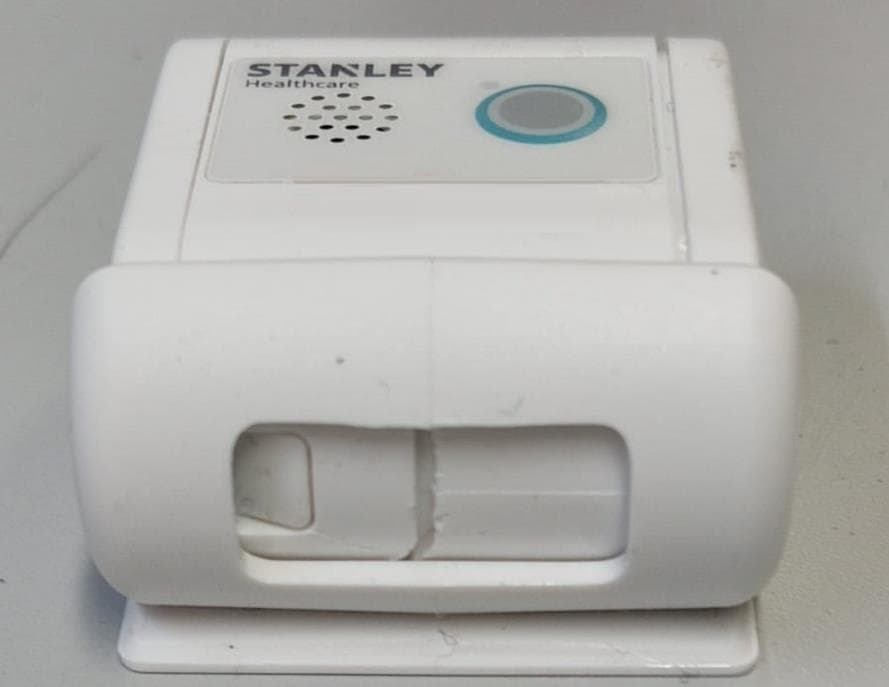
Q3HTAG1200SB
Oct 09, 2023Asset Tag
Equipment Class
DTS - Digital Transmission System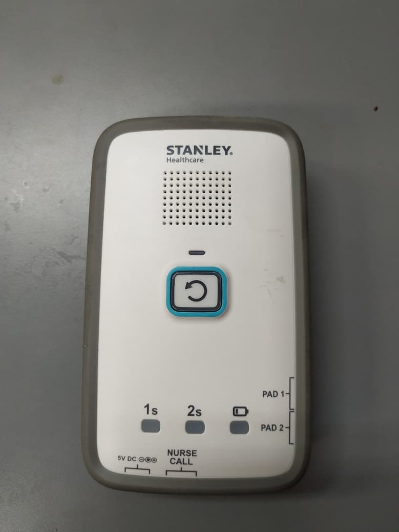
Q3HM200
Jan 05, 2021Fall Monitor, M200
Equipment Class
DTS - Digital Transmission System
Q3HTAG1200S
Mar 22, 2020T12s Asset Tag
Equipment Class
DTS - Digital Transmission System
Q3HTAGP1000
Aug 26, 2015AeroScout TAG-P1000
Equipment Class
DTS - Digital Transmission System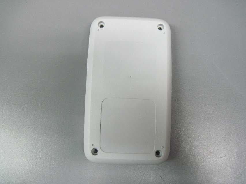
Q3HTED
Jul 01, 2015Tag/Exciter Deployment (TED) Tool TED-1000
Equipment Class
DCD - Part 15 Low Power Transmitter Below 1705 kHz