Q3HCGSHGS1000HUGS WI-FI TAG CHARGER
AeroScout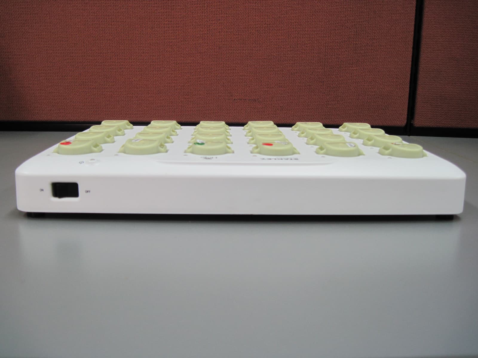
Click to zoom
Application Details
- Equipment Class
- DCD - Part 15 Low Power Transmitter Below 1705 kHz
- Date of Grant
- Nov 06, 2013
- Application Purpose
- Original Equipment
- Date of Application
- Nov 06, 2013
- Equipment Note
- HUGS WI-FI TAG CHARGER
- Frequency Range
- 0.12500000 - 0.12500000
- Company
- AeroScout
- Country
- Israel
Documents & Files
Document Text
Text extracted from the exhibit documents filed with the FCC. Open a document above to read the original.
Users Manual
User Guide Hugs ® Wi-Fi Tag Charger iii Hugs® Wi-Fi Tag Charger User Guide Table of Contents Introduction 1 Overview 1 Model Numbers 1 Intended Use 1 Safety Considerations 1 Documentation 1 Orientation 2 General Description 2 Operating and Display Modes 5 Installing the Charger 6 Wall Mounted 6 Setting Up the Charger 7 Using the Charger 8 Inserting the Tag into the Charger 8 Removing the Tag from the Charger 9 Specific Charging Capabilities 10 Overview 10 Dimensions and Weight 10 Hugs Tags States 11 Hugs Tag Behavior with Sensor Alarm 12 iv Hugs® Wi-Fi Tag Charger User Guide Maintenance 13 Operational Checks 13 Cleaning Instructions 13 Supplies and Accessories 15 Compliance and Safety 16 Introduction 1 Hugs® Wi-Fi Tag Charger User Guide Introduction Overview The Hugs on MobileView software notifies the users when the Hugs Tag battery is getting low. Placing the Hugs Tag in the charger erases all the history data from the tag, including the Kisses® bonding and the tag status. It also triggers MobileView to erase the specific patient admitting information. Model Numbers The Hugs Tag Charger part number: • CGS-HGS-1000 Based on the power supply outlet type: • CGS-HGS-1000-U U.S. outlet • CGS-HGS-1000-E European outlet • CGS-HGS-1000-J Japanese outlet • CGS-HGS-1000-UK U.K. Outlet Intended Use The Hugs Wi-Fi Tag Charger is intended for facility staff who are using the Hugs Wi-Fi Tags in conjunction with the MobileView security application. Safety Considerations • Position any trailing wires so that they are not a trip hazard and are less likely to get damaged. • Check that the plug is not damaged and that the cable is properly secured with no internal wires visible. • Where there is evidence that the supply may not be safe, such as damaged equipment or wiring, the supply should not be used until work has been done to correct this. Documentation Please refer to the following document for technical specifications for the Hugs Wi-Fi Tag Charger. • Hugs Wi-Fi Tag Charger Data Sheet p/n 0971-063-000 Orientation 2 Hugs® Wi-Fi Tag Charger User Guide Orientation General Description This section describes the parts and LEDs on the Charger. POWER SOCKET ON/OFF SWITCH CHARGER STATUS CHARGING LED CHARGING METALS Power Socket The power socket is located at the top-left side of the Charger. An external power supply is provided with the Charger. For more information about the power supply, see “Supplies and Accessories” on page 15. Orientation 3 Hugs® Wi-Fi Tag Charger User Guide Orientation General Description This section describes the parts and LEDs on the Charger. POWER SOCKET ON/OFF SWITCH CHARGER STATUS CHARGING LED CHARGING METALS Power Socket The power socket is located at the top-left side of the Charger. An external power supply is provided with the Charger. For more information about the power supply, see “Supplies and Accessories” on page 15. ON/OFF Switch After the Charger is plugged in, press the ON/OFF switch to the ON position. When the Charger is not being used, press the switch to the OFF position. Charger Status LED The Charger status LED is located at the top-right on the front of the Charger. When the Charger is plugged in and turned on, the Charger status LED turns YELLOW. Orientation 4 Hugs® Wi-Fi Tag Charger User Guide Charging LED for Hugs Tag CHARGING LED: Yellow when the Hugs Tag is correctly placed in the Charger Each Hugs Tag impression in the Charger has its own charging LED (24 LEDs in total). There are three (3) available colors for the LEDs: GREEN, YELLOW and RED. For more information about the LED color indications, see “Operating and Display Modes” on page 5. Charging Metals The charging metals are located on either side of the inside of the Hugs Tag impression. Charging for the Hugs Tag only begins once the charging metals are in contact with the metal in the tag slots Orientation 5 Hugs® Wi-Fi Tag Charger User Guide Operating and Display Modes The following table describes the LED indications for the Hugs Tag Charger. ColorDescription GREENBattery is fully charged. YELLOWCharging in progress. RED FLASHINGIssue with the Hugs Tag. Remove and replace the tag. RED SOLID Issue with the Charging slot. It is not necessary to unplug the Charger. An error may possibly be cleared by switching the Charger OFF then back ON again. If the issue continues, do not use the specific Charging slot. Other slots can be used for charging. Please contact Support. OFF - NO COLORLED is does not turn on when the tag is placed in the slot– Remove the tag and replace it with a different tag. If the LED is still off, place the tag in another charging slot. If the LED is on (GREEN or AMBER) in the new slot then the problem is with the first charging slot. Do not use this slot to charge tags. If the LED in the new charging slot is off as well, then there is an issue with the tag. Discard the tag. YELLOWLocated near the ON/OFF switch indicating the Charger is ON. Installing the Charger 6 Hugs® Wi-Fi Tag Charger User Guide Installing the Charger The following items are included with the Hugs Tag Charger: • two (2) #6 Philips head screws • two (2) plastic wall anchors • Mounting plate Wall Mounted 1. Establish a location on the wall for the Hugs Tag Charger. 2. Draw two (2) holes on the wall, at a level distance 262 mm apart, from center to center. 3. Drill two holes at the marked locations on the wall. 4. Insert the plastic wall anchors in the drilled holes. 5. Mount the plate and align the anchor holes with the wall anchors. 6. Using the supplied Philips head screws, securely screw the plate to the wall. 7. Optionally, use wood screws or other suitable wall mount hardware in the remaining holes on the plate. 8. Slide the Hugs Tag Charger onto the plate to mount it on the wall. Setting Up the Charger 7 Hugs® Wi-Fi Tag Charger User Guide Setting Up the Charger 1. Plug the supplied power cable into the power socket located on the side of the Charger. 2. Plug the other end into the wall external outlet (a…
Text truncated - open the document above for the full version.
Cover Letter(s)
10 Oppenheimer St. Park Tamar, Rehovot, Israel, 76701 Tel: 972-8-936-3136 Fax: 972-8-936-5977 www.aeroscout.com Date: 11/8/13 To: Timco Engineering Inc. To Whom It May Concern We hereby authorize Mr. Shaike Raz of I.T.L. (Product Testing) Ltd (ITL) to act on our behalf regarding the FCC Certification Process for the following application: Model: CGS-HGS-1000 FCC ID: Q3HCGSHGS1000 Thank you, Sincerely, Signature: Reuven Amsalem VP HW R&D
Cover Letter(s)
10 Oppenheimer St. Park Tamar, Rehovot, Israel, 76701 Tel: 972-8-936-3136 Fax: 972-8-936-5977 www.aeroscout.com Date: 11/8/13 To: Timco Engineering Inc. To Whom It May Concern We hereby authorize Mr. Shaike Raz of I.T.L. (Product Testing) Ltd (ITL) to sign FORM 731 on our behalf for the following application: Model: CGS-HGS-1000 FCC ID: Q3HCGSHGS1000 Thank you, Sincerely, Signature: Reuven Amsalem VP HW R&D
Cover Letter(s)
10 Oppenheimer St. Park Tamar, Rehovot, Israel, 76701 Tel: 972-8-936-3136 Fax: 972-8-936-5977 www.aeroscout.com Date: 12/8/13 Ref: CGS-HGS-1000 FCC ID: Q3HCGSHGS1000 Confidentiality Request To: Federal Communications Commission Confidentiality Request regarding application for certification of FCC ID: Q3HCGSHGS1000 Pursuant to Sections 0.457 and 0.459 of the Commission’s Rules, we hereby request confidential treatment of information accompanying this application as outlined below: a. CONF APPENDIX CGS-HGS-1000 Schem.pdf b. CONF APPENDIX CGS-HGS-1000 PartsLst.pdf c. CONF APPENDIX CGS-HGS-1000 BlkDia.pdf The above materials contain trade secrets and proprietary information not customarily released to the public. The public disclosure of these materials may be harmful to the applicant and provide unjustified benefits to its competitors. Sincerely, Signature: Reuven Amsalem VP HW R&D
Operational Description
10 Oppenheimer St. Park Tamar, Rehovot, Israel, 76701 Tel: 972-8-936-3136 Fax: 972-8-936-5977 www.aeroscout.com Operational Description CGS-HGS-1000 The primary purpose of the Hugs Wi-Fi Tag Charger (CGS-HGS-1000) is to charge the Hugs tag batteries (TAG-HGS-1000). The charger includes 24 identical charging cells and support 24 batteries charging simultaneously. Charging station powered by 12Vdc output external adapter that supports 110/220 V AC input voltage level with auto-select (no switch needed). 12V Power supply plug is located on the right side of the Charger and ON/OFF switch is located at the back of the Charger that controls the entire board. The Battery charging progress indicated by 3-collored LED (each cell has individual indication LED). Charger contains TAG T1200 (TAG1200) that works as RF Wi-Fi transceiver for Wi-Fi Network communication and charger Firmware updates. Additionally, Charger includes LF (125KHz) transmitting capabilities that provide communication with the charged HUGS TAGs at the end of charge.
Parts List/Tune Up Info
10 Oppenheimer St. Park Tamar, Rehovot, Israel, 76701 Tel: 972-8-936-3136 Fax: 972-8-936-5977 www.aeroscout.com Date: 11/8/13 To: Federal Communications Commission Declaration Subject: Tune up procedure CGS-HGS-1000 FCC ID: Q3HCGSHGS1000 No manual tune-up procedure required. Sincerely, Signature: Reuven Amsalem VP HW R&D
Test Report
Test Report E128930.00 AeroScout Ltd. Page 1 of 31 FCC ACC M Ver 1.1 05Mayl 2000 DATE: 14 August 2013 I.T.L. (PRODUCT TESTING) LTD. FCC Radio Test Report for AeroScout Ltd. Equipment under test: Hugs Wi-Fi Tag Charger CGS-HGS-1000 Written by: _____________________________ R. Pinchuck, Documentation Approved by: _____________________________ A. Sharabi, Test Engineer Approved by: _____________________________ I. Raz, EMC Laboratory Manager This report must not be reproduced, except in full, without the written permission of I.T.L. (Product Testing) Ltd. This report relates only to items tested. Test Report E128930.00 AeroScout Ltd. Page 2 of 31 FCC ACC M Ver 1.1 05Mayl 2000 Measurement/Technical Report for AeroScout Ltd. Hugs Wi-Fi Tag Charger CGS-HGS-1000 FCC ID: Q3HCGSHGS1000 IC: 5115A-CGSHGS1000 This report concerns: Original Grant: X Class I change: Class II change: Equipment Type: Part 15 Low Power Transmitter Below 1705 kHz Limits used: 47CFR15 Section 15.209 47CFR15 Section 15.207 Application for Certification Applicant for this device: prepared by: (different from "prepared by") Ishaishou Raz Reuven Amsalem ITL (Product Testing) Ltd. AeroScout Ltd. Kfar Bin Nun 3 Pekeris St. D.N. Shimshon 99780 Einstein Entrance 4 th Floor Israel Rechovot 76702 e-mail [email protected] Israel Tel: + 972 - 8 - 936 - 9393 Fax: + 972 - 8- 936 - 8977 e-mail: [email protected] Test Report E128930.00 AeroScout Ltd. Page 3 of 31 FCC ACC M Ver 1.1 05Mayl 2000 TABLE OF CONTENTS 1. GENERAL INFORMATION ------------------------------------------------------------------------------- 4 1.1 Administrative Information ................................................................................. 4 1.2 List of Accreditations ......................................................................................... 5 1.3 Product Description ........................................................................................... 6 1.4 Test Methodology .............................................................................................. 6 1.5 Test Facility ....................................................................................................... 6 1.6 Measurement Uncertainty ................................................................................. 6 2. SYSTEM TEST CONFIGURATION --------------------------------------------------------------------- 7 2.1 Justification ........................................................................................................ 7 2.1 Special Accessories .......................................................................................... 7 2.2 Equipment Modifications ................................................................................... 7 2.3 Configuration of Tested System ........................................................................ 7 3. TEST SET-UP PHOTOS ----------------------------------------------------------------------------------- 8 4. CONDUCTED EMISSION FROM AC PORTS ------------------------------------------------------ 10 4.1 Test Specification ............................................................................................ 10 4.2 Test Procedure ................................................................................................ 10 4.3 Test Results..................................................................................................... 11 4.1 Test Equipment Used, Conducted Emission ................................................... 16 5. BANDWIDTH ------------------------------------------------------------------------------------------------ 17 5.1 Test Specification ............................................................................................ 17 5.2 Conclusions ..................................................................................................... 17 6. FIELD STRENGTH OF FUNDAMENTAL ------------------------------------------------------------ 19 6.1 Test Specification ............................................................................................ 19 6.2 Test Procedure ................................................................................................ 19 6.3 Test Results..................................................................................................... 19 6.4 Test Equipment Used, Field Strength of Fundamental ................................... 21 7. RADIATED EMISSION, 9 KHZ – 30 MHZ ------------------------------------------------------------ 22 7.1 Test Specification ............................................................................................ 22 7.2 Test Procedure ................................................................................................ 22 7.3 Test Results..................................................................................................... 22 7.4 Test Instrumentation Used, Radiated Measurements ..................................... 23 7.5 Field Strength Calculation ............................................................................... 23 8. SPURIOUS RADIATED EMISSION-------------------------------------------------------------------- 24 8.1 Test Specification ............................................................................................ 24 8.2 Test Procedure ................................................................................................ 24 8.3 Test Results..................................................................................................... 24 8.4 Test Equipment Used, Radiated Measurements............................................. 25 9. APPENDIX A - CORRECTION FACTORS ----------------------------------------------------------- 26 9.1 Correction factors for CABLE ......................................................................... 26 9.2 Correction factors for CABLE ......................................................................... 27 9.3 Correction factors for…
Text truncated - open the document above for the full version.
Contact Information
Applicant
Reuven Amsalem(VP HW R&D)
Test Firm
Israel Testing LaboratoriesIIan Cohen
Technical Specifications
| # | Rule Parts | Frequency Range | Power Output |
|---|---|---|---|
| 1 | 15C | 0.125 MHz - 0.125 MHz | - |
Other Applications from AeroScout
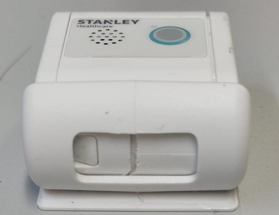
Q3HTAG1200SB
Oct 09, 2023Asset Tag
Equipment Class
DTS - Digital Transmission System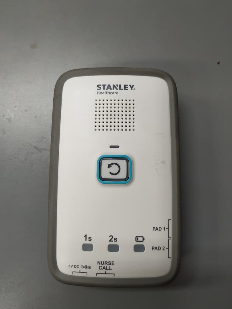
Q3HM200
Jan 05, 2021Fall Monitor, M200
Equipment Class
DTS - Digital Transmission System
Q3HTAG1200S
Mar 22, 2020T12s Asset Tag
Equipment Class
DTS - Digital Transmission System
Q3HTAGP1000
Aug 26, 2015AeroScout TAG-P1000
Equipment Class
DTS - Digital Transmission System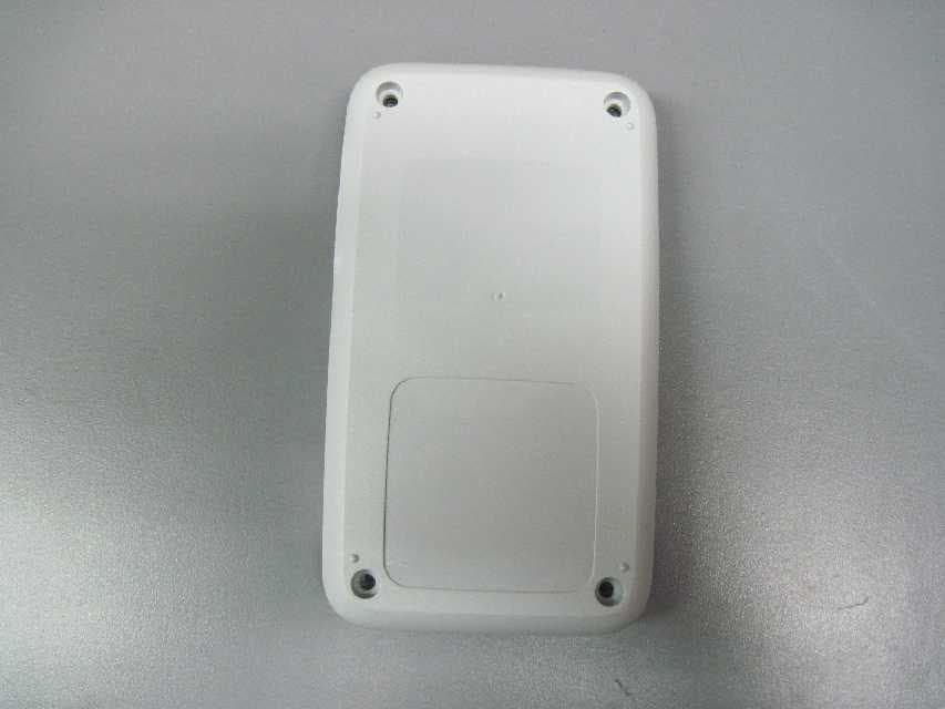
Q3HTED
Jul 01, 2015Tag/Exciter Deployment (TED) Tool TED-1000
Equipment Class
DCD - Part 15 Low Power Transmitter Below 1705 kHz