Q3HFMAeroScout Fall Monitor M310, M210
AeroScout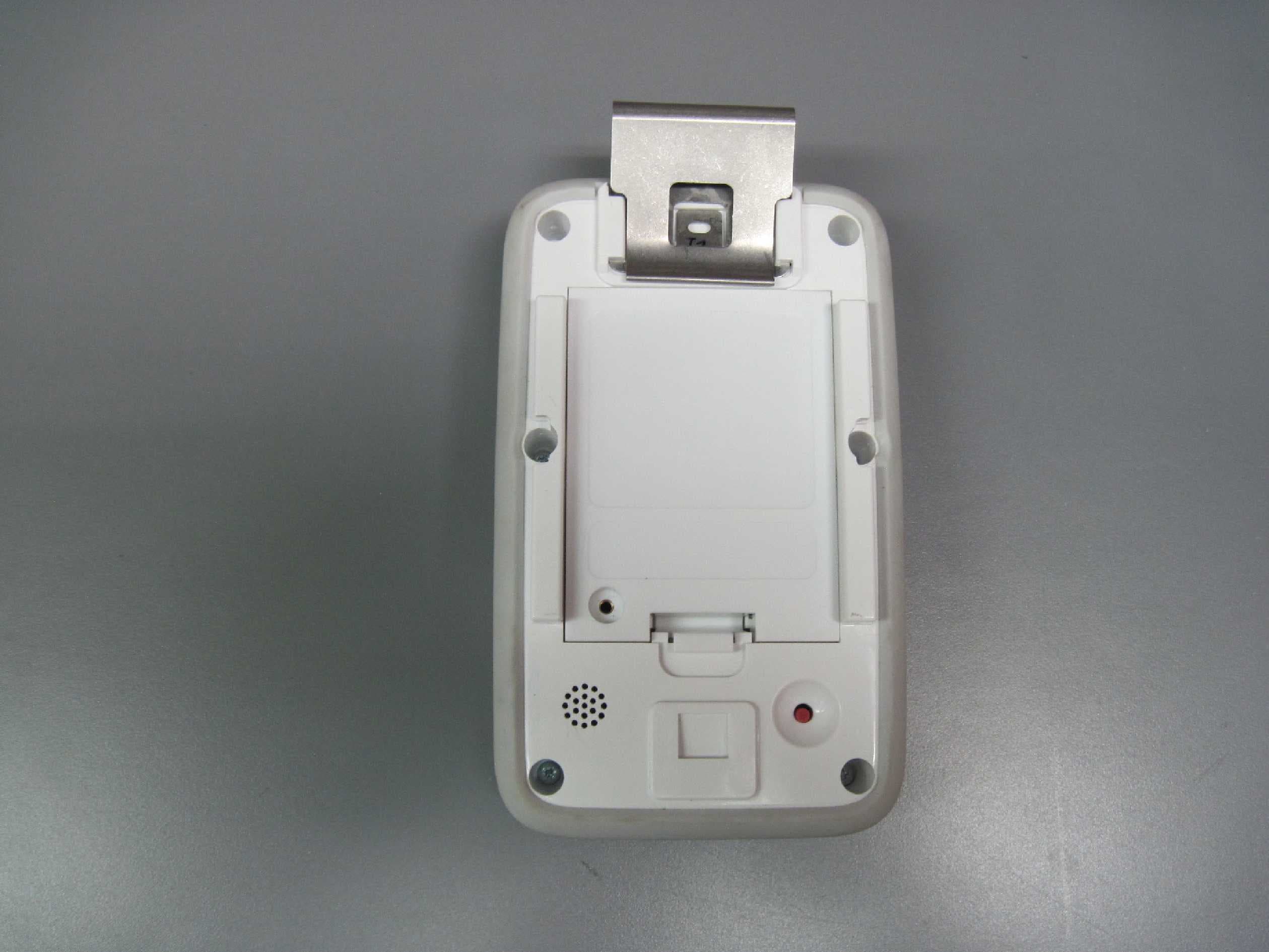
Click to zoom
Application Details
- Equipment Class
- DTS - Digital Transmission System
- Date of Grant
- May 03, 2015
- Application Purpose
- Original Equipment
- Date of Application
- May 03, 2015
- Equipment Note
- AeroScout Fall Monitor M310, M210
- Frequency Range
- 912.40000000 - 919.90000000
- Company
- AeroScout
- Country
- Israel
Documents & Files
Document Text
Text extracted from the exhibit documents filed with the FCC. Open a document above to read the original.
Users Manual
[Safe. Secure. Efficient.] Fall Management System M310 Fall Monitor Setup & User Guide For Evaluation Purposes Copyright Information All content herein is the property of STANLEY Healthcare, its Affiliates, or their content suppliers and is protected by United States and international copyright laws. The compilation of all content is likewise the exclusive property of STANLEY Healthcare (or the Affiliate identified in any copyright notice) and is protected by United States and international copyright laws. The trademarks, service marks and logos (the ‘Trademarks’) used and displayed in this publication are registered and unregistered Trademarks of STANLEY Healthcare, its Affiliates and others. Nothing herein should be construed as granting, by implication, estoppel or otherwise, any license or right to use any Trademark displayed herein without the prior consent of the Trademark owner. STANLEY and the STANLEY design are two of the trademarks owned by STANLEY Healthcare and/or its Affiliates (“STANLEY Trademarks”). STANLEY Trademarks may not be used in connection with any product or service that is not manufactured by or under license from STANLEY Healthcare or its appropriate Affiliate. Important Recommendation STANLEY Healthcare’s systems are designed to assist staff in providing a high degree of safety for people and assets and therefore should be used as a component of a comprehensive safety program of policies, procedures, and processes. As with every safety system, STANLEY Healthcare highly recommends regular system operational checks to verify functional integrity. There are no known issues with the usage of this equipment in association with other investigations or treatments at the facility. Cautions and Warnings ii M310 Fall Monitor – Setup & User Guide FAILURE TO HEED THE FOLLOWING CAUTIONS COULD RESULT IN HARM TO YOUR SYSTEM OR CAUSE IT TO FUNCTION IMPROPERLY, INTERMITTENTLY, OR NOT AT ALL. • Use the M310 Fall Monitor only with approved accessories. • Remove batteries when the Monitor is not in use to avoid battery power loss. • Use care when connecting the Sensormat® pads. Gently remove or connect cords. Pulling on cords may damage them and/or result in system failure. CAUTION M310 Fall Monitor – Setup & User Guide iii FAILURE TO HEED THE FOLLOWING WARNINGS COULD RESULT IN INJURY TO OR THE DEATH OF PERSONS IN YOUR CARE. • A low battery condition in the Monitor is indicated by the Low Battery indicator flashing YELLOW once every 3 seconds. Immediately change the monitor’s batteries. • Test the M310 Fall Monitor and Sensormat pad before each use and inspect the cords and pads for signs of damage. Immediately replace any components with signs of wear or damage. • Sensormats may not be effective with air type bed mattresses or air type chair cushion pads; test before using. • Do not place the monitor within 1 ft. (0.3m) of and facing the resident. Placing the Monitor on a wheelchair back is acceptable as long as the monitor is facing away from the resident. • The M310 Fall Monitor is only one part of your facility’s fall management program. The M310 Fall Monitor is not a substitute for proper nursing care or routine visual monitoring by caregivers. The effectiveness of the M310 Fall Monitor relies entirely on an immediate response by the caregiver to the M310 Fall Monitor system alarm. • The M310 Fall Monitor system will not stop a person from leaving a bed or chair. It is intended only to alert a caregiver that a patient or resident may need assistance. Other interventions may be required. • Keep the Sensormat pad flat at all times. Folding the pad may damage it. Do not use the pad if it has been folded. • Do not immerse the Sensormat pads in liquids. The pad will not operate properly if the pad is exposed to excessive liquids. If the pad is immersed in liquid, discard it immediately. • Operators of this equipment must be familiar with the functions and usage as described in this manual, and must be properly trained in the resident care policies and procedures of the facility. • Any modification of this equipment is not allowed, voids all warranties, and may result in injury to or death of persons in your care. WARNING CAUTION RISK OF EXPLOSION IF BATTERY IS REPLACED BY AN INCORRECT TYPE. DISPOSE OF USED BATTERIES ACCORDING TO THE INSTRUCTIONS. ATTENTION RISQUE D’EXPLOSION SI LA PILE EST REMPLACÉE PAR UN TYPE INCORRECT. SE DÉBARRASSER DES PILES USAGÉES SELON LES INSTRUCTIONS. iv M310 Fall Monitor – Setup & User Guide Contents Copyright Information ....................................................................................................ii Important Recommendation .......................................................................................ii Cautions and Warnings...................................................................................................ii Image of components to go here ..............................................................................vi Introduction .................................................................................................1 Check Your Shipment ......................................................................................................1 Other Components Sold Separately ..........................................................................1 General Overview .......................................................................................2 Hardware Features ....................................................................................3 Speaker Opening ..............................................................................................................4 Reset Button .......................................................................................................................4 Status Indicators ...............................................................................................................4 Wheelchair Mounting Clips ................................…
Text truncated - open the document above for the full version.
Cover Letter(s)
Date:17December2014 Federal Communications Commission Authorization and Evaluation Division Subject: Confidentiality Request regarding application for certification of FCC ID:Q3HFM Dear Sirs Pursuant to Sections 0.457 and 0.459 of the Commission’s Rules, we hereby request confidential treatment of information accompanying this application as outlined below: CONF APPENDIXM310Schem.pdf CONF APPENDIXM310PartsLst.pdf CONF APPENDIXM310BlkDia.pdf CONF APPENDIXM310 OpDes.pdf The above materials contain trade secrets and proprietary information not customarily released to the public. The public disclosure of these materials may be harmful to the applicant and provideunjustified benefits to its competitors. The applicant understands that pursuant to Section 0.457 of the Rules, disclosure of this application and all accompanying documentation will not be made before the date of the Grant for this application. Sincerely, Signature: Reuven Amsalem VP HW R&D
Cover Letter(s)
17 December 2014 Form 731 Signature Authorization Letter To: Timco Engineering Inc. To Whom It May Concern We hereby authorize Shaike Raz of ITL as an authorized individual to sign for Form 731 on behalf of AeroScout Ltd for the FCC ID: Q3HFM certification application. Thank you, Signature: Reuven Amsalem VP HW R&D Aeroscout LTD.
Cover Letter(s)
17December2014 To: Timco Engineering Inc. To Whom It May Concern We hereby authorize Shaike Raz of ITL to act on the behalf ofAeroScout Ltd., regarding the FCCcertificationprocess for the following application: FCC ID:Q3HFM Thank you, Signature: Reuven Amsalem VP HW R&D Aeroscout LTD.
Cover Letter(s)
10 OppenheimerSt. ParkTamar, Rehovot, Israel, 76701 Tel: 972-8-936-3136 Fax: 972-8-936-5977 www.aeroscout.com Date:December 17, 2014 Attn:Reviewing Engineer Federal Communications Commission 7435 Oakland Mills Road Columbia, MD 21046 To Whom It May Concern: The AeroScoutFall Monitor, FCC ID:Q3HFM, and label are so small that itcannot include the statement specified in FCC Part 15 Sub-part A, Section 15.19 (a) (3) “This device complies with Part 15 of the FCC Rules. Operation is subject to the following two conditions: (1)This device may not cause harmful interference and (2)This device must accept any interference received, including interference that may cause undesired operation." Due to this reason, we are using the provisions of Part 15 Sub-part A, Section 15.19 (a) (5) and this statement appears in a prominent location in the user manual. Please contact me if there is any information you may need. Sincerely, Signature: Reuven Amsalem VP HW R&D
ID Label/Location Info
Label Location
Internal Photos
915MHzTop Antenna 915MHzSide Antenna 915MHzMHz Top Antennas 915MHzSide Antenna
Parts List/Tune Up Info
Date:17/12/2014 Declaration Subject: Tune up procedure FCC ID: Q3HFM No manual tune-up procedure required. Sincerely, Signature: Reuven Amsalem VP HW R&D Aeroscout LTD.
Test Report
Test Report E143010.01AeroScout Ltd.Page1of78 FCC ACC M Ver 1.228 February 2011 DATE:16April2015 I.T.L.(PRODUCT TESTING) LTD. FCC Radio Test Report for AeroScout Ltd. Equipment under test: Fall Monitor M310, M210* *Seecustomer’s declaration on page 6 Approved by:_____________________________ M. Zohar,Test Engineer Approved by:_____________________________ For: D. Shidlowsky, Documentation This report mustnot be reproduced, except in full, without the written permission of I.T.L. (Product Testing) Ltd. This report relates only to items tested. Test Report E143010.01AeroScout Ltd.Page2of78 FCC ACC M Ver 1.228 February 2011 Measurement/Technical Report for AeroScout Ltd. Fall Monitor M310 FCC ID:Q3HFM IC:5115A-FM 16April2015 This report concerns:Original Grant:X Class IChange: Class II Change: Equipment type:Spread Spectrum/Digital Device 912-920MHz Limits used:47CFR15 Section 15.247 Measurement procedure used isKDB 558074 D01v03r02 andANSI C63.4-2009. Application for CertificationApplicant for this device: prepared by:(different from "prepared by") R. PinchuckReuven Amsalem ITL (ProductTesting) Ltd.3 Pekeris St., Einstein Entrance 1Bat Sheva StreetRechovot 76702 Lod 7116002Israel IsraelTel:+972-8-936-9393 [email protected]:+972-8-936-5977 e-mail:[email protected] Test Report E143010.01AeroScout Ltd.Page3of78 FCC ACC M Ver 1.228 February 2011 TABLEOF CONTENTS 1.GENERAL INFORMATION-------------------------------------------------------------------------------5 1.1Administrative Information................................................................................5 1.2List of Accreditations........................................................................................7 1.3Product Description..........................................................................................8 1.4Test Methodology.............................................................................................8 1.5Test Facility.......................................................................................................8 1.6Measurement Uncertainty................................................................................8 2.SYSTEM TEST CONFIGURATION---------------------------------------------------------------------9 2.1Justification.......................................................................................................9 2.2EUT Exercise Software....................................................................................9 2.3Special Accessories.........................................................................................9 2.4Equipment Modifications..................................................................................9 2.5Configuration of Tested System.....................................................................10 3.CONDUCTED & RADIATEDMEASUREMENT TEST SET-UP PHOTOS------------------11 4.CONDUCTED EMISSION FROM AC PORTS-----------------------------------------------------14 4.1Test Specification...........................................................................................14 4.2Test Procedure...............................................................................................14 4.3Test Results....................................................................................................15 4.1Test Equipment Used, Conducted Emission..................................................20 5.6 DB MINIMUM BANDWIDTH-------------------------------------------------------------------------21 5.1Test procedure................................................................................................21 5.2Results Table..................................................................................................23 5.3Test Equipment Used; 6 dB Minimum Bandwidth..........................................24 6.26 DBMINIMUM BANDWIDTH------------------------------------------------------------------------25 6.1Test procedure................................................................................................25 6.2Results table...................................................................................................27 6.3Test Equipment Used; 26 dB Minimum Bandwidth........................................28 7.MAXIMUMTRANSMITTED PEAK POWER OUTPUT-------------------------------------------29 7.1Test procedure................................................................................................29 7.2Results table...................................................................................................33 7.3Test Equipment Used; Peak Power Output....................................................34 8.BAND EDGE SPECTRUM------------------------------------------------------------------------------35 8.1Test procedure................................................................................................35 8.2Results table...................................................................................................37 8.3Test Equipment Used; Band Edge Spectrum.................................................38 9.RADIATED EMISSION, 9KHZ–30 MHZ-----------------------------------------------------------39 9.1Test Specification...........................................................................................39 9.2Test Procedure...............................................................................................39 9.3Measured Data...............................................................................................39 9.4Test Instrumentation Used; Radiated Measurements....................................40 9.5Field Strength Calculation..............................................................................41 10.SPURIOUS RADIATED EMISSION, 30–10000 MHZ-------------------------------------------42 10.1Radiated Emission 30-10000 MHz.................................................................42 10.2Test Data...................…
Text truncated - open the document above for the full version.
Contact Information
Applicant
Reuven Amsalem(VP HW R&D)
Test Firm
Israel Testing LaboratoriesIIan Cohen
Technical Specifications
| # | Rule Parts | Frequency Range | Power Output |
|---|---|---|---|
| 1 | 15C | 912.4 MHz - 919.9 MHz | 2.75 mW |
Other Applications from AeroScout
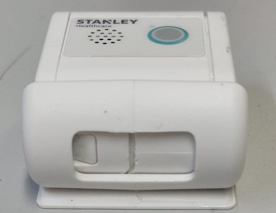
Q3HTAG1200SB
Oct 09, 2023Asset Tag
Equipment Class
DTS - Digital Transmission System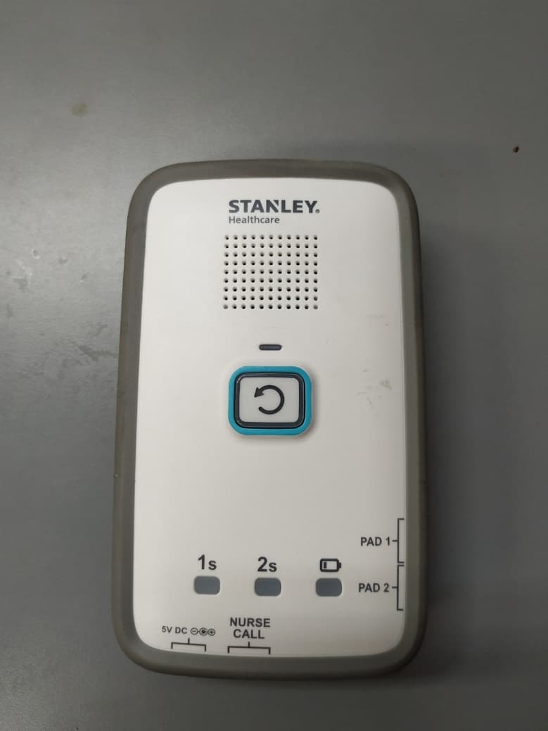
Q3HM200
Jan 05, 2021Fall Monitor, M200
Equipment Class
DTS - Digital Transmission System
Q3HTAG1200S
Mar 22, 2020T12s Asset Tag
Equipment Class
DTS - Digital Transmission System
Q3HTAGP1000
Aug 26, 2015AeroScout TAG-P1000
Equipment Class
DTS - Digital Transmission System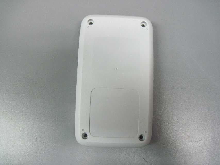
Q3HTED
Jul 01, 2015Tag/Exciter Deployment (TED) Tool TED-1000
Equipment Class
DCD - Part 15 Low Power Transmitter Below 1705 kHz