Q3HTAG1200AEROSCOUT TAG-1200 BI-DIRECTIONAL WIFI MODULE
AeroScout
Click to zoom
Application Details
- Equipment Class
- DTS - Digital Transmission System
- Date of Grant
- Aug 18, 2013
- Application Purpose
- Original Equipment
- Date of Application
- Aug 18, 2013
- Equipment Note
- AEROSCOUT TAG-1200 BI-DIRECTIONAL WIFI MODULE
- Frequency Range
- 2412.00000000 - 2462.00000000
- Company
- AeroScout
- Country
- Israel
Documents & Files
Document Text
Text extracted from the exhibit documents filed with the FCC. Open a document above to read the original.
Users Manual
Stanley Healthcare Confidential and proprietary Preliminary information – Subject to change. Ver. 1.0_DM Stanley Healthcare TAG1200 Module Data Sheet Small Form Factor Module that includes Wi-Fi Communication – For OEM Installation only Overview The integration tag is designed for OEM only technology partners who wish to embed Stanley Healthcare location technology into their products. Key Features Compact Form Factor The TAG1200 module Tag is designed for OEM applications that require assets location. The module is based on the smallest asset tag of the Stanley Healthcare Tag family and it includes additional mounting screws, enabling it to be easily embedded into other product enclosures. Wi-Fi Compatibility Stanley Healthcare Tags are 802.11b/g/n compatible working on the 2.4GHz band. The tag’s clear channel sensing techniques avoid interference with Wi-Fi networks. The tag supports Stanley Healthcare IBSS and Cisco CCX Location beaconing protocols. The TAG1200 module support Wi-Fi Bi-directional communication to allow Over-the-Air firmware and configuration upgrade using the Stanley Healthcare Mobile View application. Choke-Point Detection Capabilities Using the Stanley Healthcare Exciter, distinct tag presence can be automatically detected and behavior can be modified as the tag passes through a choke point, such as a doorway or gate. This includes turning tags on/off, or changing tag transmission rates. In addition, choke points enable precise real-time alerts, through the Stanley Healthcare MobileView software. Ultrasound Receiver The TAG1200 module is equipped with an ultrasound receiver that picks up the ultrasound transmissions from EX4100 and EX4200 Ultrasound Exciters. The tag transmits the Exciter ID to the Stanley Healthcare software via the Wi- Fi network. Using the ultrasound communication the Stanley Healthcare system can achieve room level accuracy. Tag Management The TAG1200 module Tag can be programmed via a wireless interface using the Stanley Healthcare Tag Activator. Together with the AeroScout Tag Manager software it allows for easy and efficient Tag configuration, activation or deactivation and programming. The tag can also be programed over-the-air using the MobileView application. FCC STATEMENT This equipment has been tested and found to comply with the limits for a Class B digital device, pursuant to Part 15 of the FCC rules. These limits are designed to provide reasonable protection against harmful interference in a residential installation. This equipment generates, uses and can radiate radio frequency energy and, if not installed and used in accordance with the instructions, may cause harmful interference to radio communications. However, there is no guarantee that interference will not occur in a particular installation. If this equipment does cause harmful interference to radio or television reception, which can be determined by turning the equipment off and on, the user is encouraged to try to correct the interference by one or more of the following measures: a. Reorient or relocate the receiving antenna. b. Increase the separation between the equipment and receiver. c. Connect the equipment to an outlet on a circuit different from that to which the receiver is connected. d. Consult the dealer or an experienced radio/TV technician. This device complies with Part 15 of the FCC Rules. Operation is subject to the following two conditions: 1. This device may not cause harmful interference 2. This device must accept any interference received, including interference that may cause undesired operation. Stanley Healthcare Confidential and proprietary Preliminary information – Subject to change. Ver. 1.0_DM Connectors and Electrical Interfaces 16 pin connector A 16-pin serial connector is used as an additional option to externally power the tag. In addition it provides serial interface for telemetry and configuration of the module Pin Description Pin Description 1 Pushbutton_2 9 Pushbutton_1 2 UART1_TX 10 UART1_RX 3 VCC_3.3V 11 UART2_RX 4 UART2_TX 12 NC 5 GND 13 NC 6 RESET 14 NC 7 WAKEUP 15 NC 8 ENABLE 16 NC Mechanical Drawings Installation Instruction The TAG1200 module should be installed inside equipment enclosure by keeping its location as far as possible from metal parts to prevent RF performance degradation Before plugging the module into device, turn off the device power and verify there is no live power on the connector pins. Connect the TAG1200 module to the device by using board to board or wire to board connector. Verify straight insertion and make sure there are no bent or unconnected pins. Use up to three screws (provided with the TAG1200 Module) to mount the module to the host device mechanics. Turn the host power on. The device is ready for use. OEM Instructions a. The module is limited to OEM installation ONLY. b. The OEM integrator is responsible for ensuring that the end-user has no manual instructions to remove or install the module. c. The module is limited to installation in mobile or fixed applications, according to Part 2.1091(b); d. Separate approval is required for all other operating configurations, including portable configurations with respect to Part 2.1093 and different antenna configurations; e. Labeling instructions of finished products must contain the following - “Contains Transmitter Module FCC ID: Q3HTAG1200, IC: 5115A-TAG1200” The OEM/Integrator must include the following instructions/statements in the host user’s manual (i.e. end product): a. Statements required per FCC Part 15.19 and 15.21; b. End-users must be provided with transmitter/antenna installation requirements and operating conditions for satisfying RF exposure compliance: i. A separate section should clearly state “FCC RF Exposure requirements: “ ii. Required operating conditions for end users iii. Antenna/or transmitter installation requirements, where relevant (For example: whether the antenna used with this module must be installed to provide a separation dista…
Text truncated - open the document above for the full version.
Cover Letter(s)
10 Oppenheimer St. Park Tamar, Rehovot, Israel, 76701 Tel: 972-8-936-3136 Fax: 972-8-936-5977 www.aeroscout.com Date: 23/07/2013 Ref: TAG1200 FCC ID: Q3HTAG1200 Confidentiality Request To: Federal Communications Commission Confidentiality Request regarding application for certification of FCC ID: Q3HTAG1200 Pursuant to Sections 0.457 and 0.459 of the Commission’s Rules, we hereby request confidential treatment of information accompanying this application as outlined below: a. CONF APPENDIX TAG1200 Schem.pdf b. CONF APPENDIX TAG1200 PartsLst.pdf c. CONF APPENDIX TAG1200 BlkDia.pdf The above materials contain trade secrets and proprietary information not customarily released to the public. The public disclosure of these materials may be harmful to the applicant and provide unjustified benefits to its competitors. Sincerely, Signature: Reuven Amsalem VP HW R&D
Cover Letter(s)
10 Oppenheimer St. Park Tamar, Rehovot, Israel, 76701 Tel: 972-8-936-3136 Fax: 972-8-936-5977 www.aeroscout.com Date: 29/05/2013 To: Timco Engineering Inc. To Whom It May Concern We hereby authorize Mr. Shaike Raz of I.T.L. (Product Testing) Ltd (ITL) to act on our behalf regarding the FCC Certification Process for the following application: Model: TAG1200 FCC ID: Q3HTAG1200 Thank you, Sincerely, Signature: Reuven Amsalem VP HW R&D
Cover Letter(s)
10 Oppenheimer St. Park Tamar, Rehovot, Israel, 76701 Tel: 972-8-936-3136 Fax: 972-8-936-5977 www.aeroscout.com Date: 22.05.2013 Attn: Reviewing Engineer Federal Communications Commission 7435 Oakland Mills Road Columbia, MD 21046 To Whom It May Concern: The AeroScout TAG1200, FCC ID: Q3HTAG1200, and label are so small that it cannot include the statement specified in FCC Part 15 Sub-part A, Section 15.19 (a) (3) “This device complies with Part 15 of the FCC Rules. Operation is subject to the following two conditions: (1) This device may not cause harmful interference and (2) This device must accept any interference received, including interference that may cause undesired operation." Due to this reason, we are using the provisions of Part 15 Sub-part A, Section 15.19 (a) (5) and this statement appears in a prominent location in the user manual. Please contact me if there is any information you may need. Sincerely, Reuven Amsalem VP R&D AeroScout Ltd.
Cover Letter(s)
10 Oppenheimer St. Park Tamar, Rehovot, Israel, 76701 Tel: 972-8-936-3136 Fax: 972-8-936-5977 www.aeroscout.com Date: 22/05/2013 Date: Ref: Modular Approval (MA) Compliance Letter (FCC ID: Q3HTAG1200) To: Federal Communications Commission Subject: TAG1200 FCC ID: Q3HTAG1200 - MA compliance letter This letter introduces AeroScout Ltd.’s request to approve its TAG1200 according to FCC Modular Approval procedure, and to demonstrate the means to control the module as required by the MA procedure. The TAG1200 is specialty designed to monitor mobile assets tracking, and can be installed to a variety of equipment, such as medical devices, containers, manufacturing equipment and vehicles. This enables tagged items to be accurately located in real-time and in any environment – from tight indoor locations such as hospital floors to open outdoor spaces such as parking lots. The tag transmits a message to AeroScout Location Receivers or compatible Access Points in range. This provides instant acknowledgment that a tagged asset was moved. The AeroScout Visibility System can detect record and report the moving and actual location of the assets in medical environment. The TAG1200 as a module is not sold separately. The module incorporates an integral antenna its EIRP does not change between the hosts other than changes created by the host units shape influence. Due to all the above mentioned, AeroScout Ltd feels that the testing conducted by ITL to the various hosts, with the fact that AeroScout Ltd. markets the TAG1200 for use only in the hosts submitted in this application and the host manufacturer has been instructed (in the user manual) not to insert the TAG1200 in any host not included in this application, assure complete compliance with FCC MA procedure. 10 Oppenheimer St. Park Tamar, Rehovot, Israel, 76701 Tel: 972-8-936-3136 Fax: 972-8-936-5977 www.aeroscout.com As per § 15.212 Modular transmitters: Single modular transmitters must meet the following requirements to obtain a modular transmitter approval. Requirement Not Maintained Maintained (1) The radio elements of the modular transmitter must have their own shielding. The physical crystal and tuning capacitors may be located external to the shielded radio elements. Yes (2) The modular transmitter must have buffered modulation/data inputs (if such inputs are provided) to ensure that the module will comply with part 15 requirements under conditions of excessive data rates or over- modulation. Yes (3) The modular transmitter must have its own power supply regulation. Yes (4) The modular transmitter must comply with the antenna and transmission system requirements of §§15.203, 15.204(b) and 15.204(c). The antenna must either be permanently attached or employ a “unique” antenna coupler (at all connections between the module and the antenna, including the cable). The “professional installation” provision of §15.203 is not applicable to modules but can apply to limited modular approvals under paragraph (b) of this section. Yes 10 Oppenheimer St. Park Tamar, Rehovot, Israel, 76701 Tel: 972-8-936-3136 Fax: 972-8-936-5977 www.aeroscout.com As per § 15.212 Modular transmitters: Single modular transmitters must meet the following requirements to obtain a modular transmitter approval. Requirement Not Maintained Maintained (5) The modular transmitter must be tested in a stand-alone configuration, i.e. , the module must not be inside another device during testing for compliance with part 15 requirements. Unless the transmitter module will be battery powered, it must comply with the AC line conducted requirements found in §15.207. AC or DC power lines and data input/output lines connected to the module must not contain ferrites, unless they will be marketed with the module (see §15.27(a)). The length of these lines shall be the length typical of actual use or, if that length is unknown, at least 10 centimeters to insure that there is no coupling between the case of the module and supporting equipment. Any accessories, peripherals, or support equipment connected to the module during testing shall be unmodified and commercially available (see §15.31(i)). Yes (6) The modular transmitter must be equipped with either a permanently affixed label or must be capable of electronically displaying its FCC identification number. Yes Thank you, Signature: Printed Name: Reuven Amsalem VP HW R&D AeroScout Ltd.
ID Label/Location Info
L2 U2 J1 SW1 1 1 B1 1 A 1 1 A12 B2 1 - 20022012000 + C.S
Operational Description
Multiple files are bound together in this PDF Package. Adobe recommends using Adobe Reader or Adobe Acrobat version 8 or later to work with documents contained within a PDF Package. By updating to the latest version, you’ll enjoy the following benefits: • Efficient, integrated PDF viewing • Easy printing • Quick searches Don’t have the latest version of Adobe Reader? Click here to download the latest version of Adobe Reader If you already have Adobe Reader 8, click a file in this PDF Package to view it.
Operational Description
Operational Description TAG1200 Module TAG1200 module is an Active RFID tag platform which designed by AeroScout to use in RTLS system. The tag based on Wi-Fi 802.11.N transceiver (2.4GHz) and LF receiver (125KHz) which are working corporately to build the real time location mechanism. The tag can be configured to operate in different modes which change the LF and RF responding/operation accordingly. The module can be integrated into other products (such infusion pumps, electronic equipment, etc....) and by that supply tracking mechanism for the specific item. The tag is working from 3.3-2.2V DC supply which can be derived from specific battery, external battery, power supply or any other source. The tag include LED which indicates when the LF/Wi-FI are operated. In addition there are 2 call button which can be configured for specific events in the tag (initiate RF/LF or just send message).
Parts List/Tune Up Info
10 Oppenheimer St. Park Tamar, Rehovot, Israel, 76701 Tel: 972-8-936-3136 Fax: 972-8-936-5977 www.aeroscout.com Date: 29/05/2013 Ref: TAG1200 FCC ID: Q3HTAG1200 Tune up procedure To: Federal Communications Commission Subject: TAG1200 FCC ID: Q3HTAG1200 - Tune up procedure No manual tune-up procedure required. Thank you, Signature: Printed Name: Reuven Amsalem VP HW R&D AeroScout Ltd.
Test Report
Test Report E128450.01 AeroScout Ltd. Page 1 of 65 FCC ACC M Ver 1.2 28 February 2011 DATE: 16 June 2013 I.T.L. (PRODUCT TESTING) LTD. FCC Radio Test Report for AeroScout Ltd. Equipment under test: TAG1200 Bi-Directional WiFi Module TAG1200 Written by: _____________________________ R. Pinchuck, Documentation Approved by: _____________________________ A. Sharabi, Test Engineer Approved by: _____________________________ I. Raz, EMC Laboratory Manager This report must not be reproduced, except in full, without the written permission of I.T.L. (Product Testing) Ltd. This report relates only to items tested. Test Report E128450.01 AeroScout Ltd. Page 2 of 65 FCC ACC M Ver 1.2 28 February 2011 Measurement/Technical Report for AeroScout Ltd. TAG1200 Bi-Directional WiFi Module TAG1200 FCC ID: Q3HTAG1200 IC: 5115A-TAG1200 16 June 2013 This report concerns: Original Grant: X Class I Change: Class II Change: Equipment type: Bi-directional WiFi module transmitter Limits used: 47CFR15 Section 15.247 Measurement procedure used is ANSI C63.4-2003. Application for Certification Applicant for this device: prepared by: (different from "prepared by") Ishaishou Raz Reuven Amsalem ITL (Product Testing) Ltd. 3 Pekeris St., Einstein Entrance Kfar Bin Nun Rechovot 76702 D.N. Shimshon 99780 Israel Israel Tel: +972-8-936-9393 e-mail [email protected] Fax: +972-8-936-5977 e-mail: [email protected] Test Report E128450.01 AeroScout Ltd. Page 3 of 65 FCC ACC M Ver 1.2 28 February 2011 TABLE OF CONTENTS 1. GENERAL INFORMATION ------------------------------------------------------------------------------- 5 1.1 Administrative Information ................................................................................. 5 1.2 List of Accreditations ......................................................................................... 6 1.3 Product Description ........................................................................................... 7 1.4 Test Methodology .............................................................................................. 7 1.5 Test Facility ....................................................................................................... 7 1.6 Measurement Uncertainty ................................................................................. 7 2. SYSTEM TEST CONFIGURATION --------------------------------------------------------------------- 8 2.1 Justification ........................................................................................................ 8 2.2 EUT Exercise Software ..................................................................................... 8 2.3 Special Accessories .......................................................................................... 8 2.4 Equipment Modifications ................................................................................... 8 2.5 Configuration of Tested System ........................................................................ 9 3. CONDUCTED AND RADIATED MEASUREMENT TEST SET-UP PHOTO ----------------10 4. 6 DB MINIMUM BANDWIDTH --------------------------------------------------------------------------12 4.1 Test procedure ................................................................................................ 12 4.2 Results table .................................................................................................... 14 4.3 Test Equipment Used. ..................................................................................... 15 5. 26 DB MINIMUM BANDWIDTH-------------------------------------------------------------------------16 5.1 Test procedure ................................................................................................ 16 5.2 Results table .................................................................................................... 18 5.3 Test Equipment Used. ..................................................................................... 19 6. MAXIMUM TRANSMITTED PEAK POWER OUTPUT -------------------------------------------20 6.1 Test procedure ................................................................................................ 20 6.2 Results table .................................................................................................... 22 6.3 Test Equipment Used. ..................................................................................... 23 7. PEAK POWER OUTPUT OUT OF 2400-2483.5 MHZ BAND -----------------------------------24 7.1 Test procedure ................................................................................................ 24 7.2 Results ............................................................................................................. 27 7.3 Test Equipment Used. ..................................................................................... 28 8. BAND EDGE SPECTRUM -------------------------------------------------------------------------------29 8.1 Test procedure ................................................................................................ 29 8.2 Results table .................................................................................................... 30 8.3 Test Equipment Used. ..................................................................................... 31 9. RADIATED EMISSION, 9 KHZ – 30 MHZ -----------------------------------------------------------32 9.1 Test Specification ............................................................................................ 32 9.2 Test Procedure ................................................................................................ 32 9.3 Measured Data ................................................................................................ 32 9.4 Test Instrumentation Used, Radiated Measurements ..................................... 33 9.5 Field Strength Calculation ............................................................................... 34 10.…
Text truncated - open the document above for the full version.
Contact Information
Applicant
Reuven Amsalem(VP HW R&D)
Test Firm
Israel Testing LaboratoriesIIan Cohen
Technical Specifications
| # | Rule Parts | Frequency Range | Power Output |
|---|---|---|---|
| 1 | 15C | 2.41 GHz - 2.46 GHz | 177.00 mW |
Other Applications from AeroScout
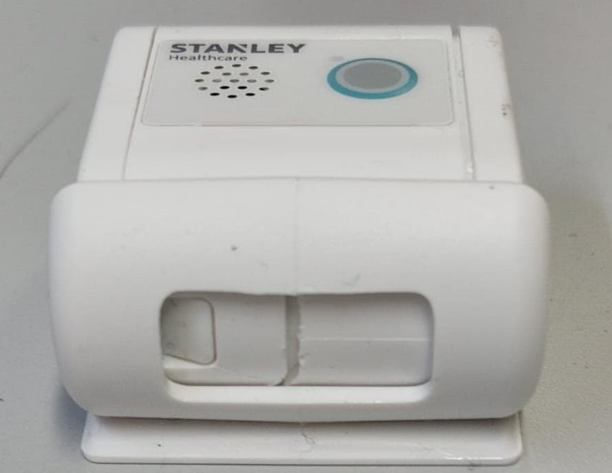
Q3HTAG1200SB
Oct 09, 2023Asset Tag
Equipment Class
DTS - Digital Transmission System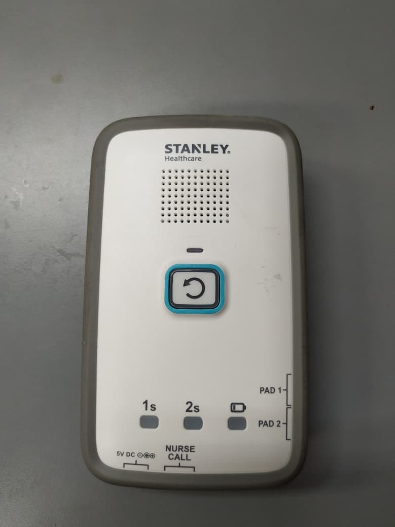
Q3HM200
Jan 05, 2021Fall Monitor, M200
Equipment Class
DTS - Digital Transmission System
Q3HTAG1200S
Mar 22, 2020T12s Asset Tag
Equipment Class
DTS - Digital Transmission System
Q3HTAGP1000
Aug 26, 2015AeroScout TAG-P1000
Equipment Class
DTS - Digital Transmission System
Q3HTED
Jul 01, 2015Tag/Exciter Deployment (TED) Tool TED-1000
Equipment Class
DCD - Part 15 Low Power Transmitter Below 1705 kHz