Q4EAVHR-5000Dual Band Repeater (Model: AVHR-5000)
OPISYS Incorporated
Click to zoom
Application Details
- Equipment Class
- PCB - PCS Licensed Transmitter
- Date of Grant
- Apr 13, 2011
- Application Purpose
- Original Equipment
- Date of Application
- Mar 31, 2011
- Equipment Note
- Dual Band Repeater (Model: AVHR-5000)
- Frequency Range
- 1930.00000000 - 1990.00000000
- Company
- OPISYS Incorporated
- Country
- United States
Documents & Files
Document Text
Text extracted from the exhibit documents filed with the FCC. Open a document above to read the original.
Users Manual
Installation User Guide MODEL : AVHR MODEL : AVHR - - 5000 5000 Page 1 - Content - 1. General Information 1.1 Precautions 1.2 Features 2. System Components 3. Installation 3.1 Outside Antenna Installation 3.2 Inside Antenna Installation 3.3 Amplifier and Antenna Connection 3.4 Operating Instructions 4. Trouble Shooting 4.1 LED Alarm 4.2 Insufficient Outside Signal Problem 4.3 Vehicle Battery Discharge Problem 5. Specification 5.1 Amplifier Specification 5.2 Outside Antenna Specification 5.3 Inside Antenna Specification 5.4 Cigarette Power Code Specification 6. Certificates 7. Memo 1. General Information 1.1 Precautions 1.1.1 Do not drop the device - Drop could damage the product 1.1.2 Do not place near magnetic - It could be cause of malfunction 1.1.3 Product is supposed to be used with the cigarette power code. If you want to use fuse cable, please ask professional installers. 1.1.4 Please unplug either with cigarette power code or fuse cable if you don’t use - It may cause battery discharge 1.1.5 Set up product on advised location - It may not properly operate on unadvised location 1.1.6 Do not repair or remodel - It could be cause of malfunction. Please contact a store where you purchased if there is a problem 1.1.7. Do not operate device while driving - It could be cause of traffic accident 1.1.8 Turn off the ignition before set up the device. 1.1.9 Do not put the device near vehicle air bag in the car - You could be hurt by burst air bag or air bag which doesn’t operate properly 1.1.10 Do not handle with wet hands - Avoid risk of an electric shock 1.1.11 Clean up the surface where you set up inside and outside antenna - It could be cause of a traffic accident when the antennas detached from the surface. 1.1.12 Please stop use and unplug when smog comes out of the product or could detect strange odor Page 2 Reference : Things you need to know to operate the product properly Caution : Things that you need to know not to damage the product Warning : Showing instructions for users to avoid unexpected hazard 1.2 Features 1.2.1 Summary This product is installed on cars, trucks, trailers, boats and homes to improve user’s mobile phone signal. It is a RF type amplifier used for only CDMA Cellular bands in the 800MHz and PCS1900MHz . (Please see page 11 for Operating Frequency) 1.2.2 Features Page 3 I.Decrease dropped call II. Increase 2G/3G/4G data speed III. Battery life extension IV. Voice quality improvement I.Strong coverage area - Gain 55dB II. Automatic Overload Protect & Detect System - Plug and play systems III. IS-95A Spurious Specifications with 25dBm(0.3W) Output power - Providing high data communication rate IV. Complete Repeater Kit. -Providing all components for installation V. Dual Band Amplifier - 800MHz / 1900MHz VI. LED Alarm System VII. GUI(Graphic User Interface) - Please ask professional installers about GUI program. VIII. Cost Effective Application for Vehicles, Boats, and Homes - For at home users need to purchase cables, inside and outside antennas to install. Page 4 ① Inside Antenna ②AVHR-5000 ③User Manual ④cigarette power code⑤Outsider Antenna ① . Inside Antenna: connects signal between mobile phone and amplifier ②. AVHR-5000: amplifies signal from outside antenna which receives signal from a base station and sends amplified signal to mobile phone ③. User Manual: shows how to operate system ④. Cigarette Power Code : is the source of electricity ⑤. Outside Antenna: connects signal between base station and amplifier ▣ System Components 1.2.3 Installation 2. System Components Page 5 3. Installation 3.1 Outside Antenna Installation 3.1.1 Outside antenna is magnetic. So you can mount on the roof of vehicle 3.1.2 Outside antenna should be distance at least 5 feet from inside antenna 3.1.3 As showing on the picture below, suggested place to mount outside antenna is rear end of roof 3.2 Inside Antenna Installation 3.2.1 Inside antenna is self adhesive. You can place it wherever you want 3.2.2 Before installation, please remove attached paper 3.2.2 Recommend to mount under location shown on the picture Better Best Good Page 6 3.3 Amplifier and Antenna Connection 3.3.1 Place the amplifier under the seat or appropriate location. 3.4 Operating Instructions 3.4.1 As the picture shown below, plug in the cigarette power code and press red button to turn on 3.3.2 Connect inside antenna connector to repeater Page 7 3.4.2 Connect DC Jack as picture down below 3.4.3 Turn on the Switch as picture down below 3.4.4 After turning on switch, green LED light will be on(GreenLED means that system is normal mode) ※ Green and Red LED simultaneously brinks 3 times and then only green LED light will be on Page 8 4. Trouble Shooing 4.1 LED Alarm ItemGREEN LEDRED LED문제점 찾기 Setting/Resetting ON (after 3 times blinks) 3 times blinksSee 4.1.1 Normal ModeONOFFSee 4.1.2 Cellular OverloadBlink( once)-See 4.1.3 OscillationBlink(twice)-See 4.1.4 Insufficient Isolation Blink(3 times)-See 4.1.5 Alarm Checking Blink(Consecutively)-See 4.1.6 PCS Overload-Blink( once)See 4.1.3 Oscillation-Blink(twice)See 4.1.4 Insufficient Isolation -Blink(3 times)See 4.1.5 Alarm Checking -Blink(Consecutively)See 4.1.5 4.1.1 ① Check if the LED light is on, on the cigarette power code ② Verify that DC code is connected correctly 4.1.2 ① Green LED light is normal mode. If it is blinking 2-3 times in a few seconds, please see 4.1.3 ~ 4.1.6 4.1.3 ① This is normal mode that checking on input power signal and shows signal status to users. ③ It will go back to normal mode soon 4.1.4 ① There is an oscillation between inside and outside antenna. ② This status is caused by a structure around that temporarily disturbs mobile signals. Please move your vehicle to other location. LED light will turn to green Page 9 4.2 Insufficient Outside Signal Problem After repeater installed, if there is insufficient outside signal around your vehicle such as uncovered signal area, you may not use your mobile phone 4.3 Vehicle Battery Discharge Problem…
Text truncated - open the document above for the full version.
Cover Letter(s)
Opisys , Inc. Date: March 15, 2011 Federal Communications Commission 7435 Oakland Mills Road Columbia MD 21046 c.c. Compliance Certification Services Certification Division 47173 Benicia Street Fremont, CA 94538, USA To whom it may concern: I, the undersigned, hereby authorize Jin-Mo Yang,Engineering Manager of ESTECH Co., Ltd. and hereafter referred to as ESTECH, to act on our behalf in all manners relating to application for equipment authorization, including signing of all documents relating to these matters. Any and all acts carried out by Jin-Mo Yang,Engineering Manager of ESTECH Co., Ltd. on our behalf shall have the same effect as acts of our own. I, the undersigned, hereby certify that we are not subject to a denial of federal benefits, that includes FCC benefits, pursuant to Section 5301 of the Anti-Drug Abuse Act of 1988, 21 U.S.C. 853(a). In authorizing ESTECH as our agent, we still recognize that we are responsible to: a) comply with the relevant provisions of the certification program; b) make all necessary arrangements for the conduct of the evaluation, including provision for examining documentation and access to all areas, records (including internal audit reports) and personnel for the purposes of evaluation (e.g. testing, inspection, assessment, surveillance, reassessment) and resolution of complaints; c) make claims regarding certification only in respect of the scope for which certification has been granted; d) do not use our product certification in such a manner as to bring the Certification Division into disrepute and not make any statement regarding our product certification which the Certification Division may consider misleading or unauthorized; e) upon suspension or cancellation of certification, discontinue use of all advertising matter that contains any reference thereto and return any certification documents as required by the Certification Division; f) use certification only to indicate the products are certified as being in conformity with specified standards; g) endeavor to ensure that no certificate or report nor any part thereof is used in a misleading manner; h) ensure that any reference to our product certification in communication media such as documents, brochures or advertising, complies with the requirements of the Certification Division; i) keep a record of all complaints made known to the us relating to the product’s compliance with requirements of the relevant standard and to make these records available to the Certification Division when requested; j) take appropriate action with respect to such complaints and any deficiencies found in products or services that affect compliance with the requirements for certification; k) document the actions taken. This authorization is valid until further written notice from the applicant. Sincerely Yours, Justin Park , Manager Opisys,Inc. REMARK: 1. This authorization letter will be sent along with your application when filing with the Certification Division. 2. Please follow the format and type it on company letterhead and send original to us. 3. Authorized signature must be in agreement with grantee code contact in FCC database.
Cover Letter(s)
OPISYS,INC. 590 West Central Ave Unit E, Brea CA 92821 TEL : 714-990-6244 FAX : 714-990-6243 Federal Communications Commission Authorization and Evaluation Division FCC ID : Q4EAVHR-5000 Confidentiality Request Pursuant to Sections 0.457 and 0.459 of the Commission’s Rules, the Applicant hereby requests confidential treatment of information accompanying this Application as outlined below: Schematics Block Diagram The above materials contain trade secrets and proprietary information not customarily released to the public. The public disclosure of these matters might be harmful to the Applicant and provide unjustified benefits to its competitors. The Applicant understands that pursuant to Rule 0.457, disclosure of this Application and all accompanying documentation will not be made before the data of the Grant for this application. Sincerely, Justin Park , Manager Opisys,Inc.
External Photos
Front Rear Right side Out side Ant Left side Inside Ant
ID Label/Location Info
OPISYS.INC Dual Band Repeater MODEL : AVHR-5000 FCC ID : Q4EAVHR-5000 This device complies with part 15 or rhe FCC Rules. Operation is subject to the dollowing two conditions : (1) This device may not cause harmful interference, and (2) this device must accept ant interference received, including interference that may cause undesired o peration.
Internal Photos
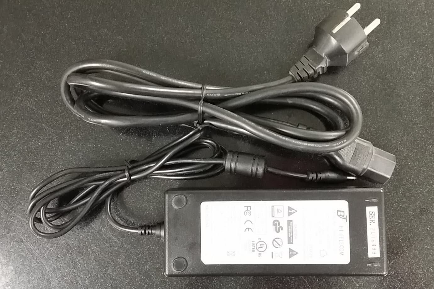
Main front Main front 1 Main rear Main rear 1 AC adapter AC adapter1 DC adapter DC adapter1
Operational Description
Page 5 1. Installation 1.1 Outside Antenna Installation 1.1.1 Outside antenna is magnetic. So you can mount on the roof of vehicle 1.1.2 Outside antenna should be distance at least 5 feet from inside antenna 1.1.3 As showing on the picture below, suggested place to mount outside antenna is rear end of roof 1.2 Inside Antenna Installation 3.2.1 Inside antenna is self adhesive. You can place it wherever you want 3.2.2 Before installation, please remove attached paper 3.2.2 Recommend to mount under location shown on the picture Better Best Good Page 6 1.3 Amplifier and Antenna Connection 1.3.1 Place the amplifier under the seat or appropriate location. 1.4 Operating Instructions 1.4.1 As the picture shown below, plug in the cigarette power code and press red button to turn on 1.3.2 Connect inside antenna connector to repeater Page 7 1.4.2 Connect DC Jack as picture down below 1.4.3 Turn on the Switch as picture down below 1.4.4 After turning on switch, green LED light will be on(GreenLED means that system is normal mode) ※ Green and Red LED simultaneously brinks 3 times and then only green LED light will be on Page 8 2. Trouble Shooing 2.1 LED Alarm ItemGREEN LEDRED LED문제점 찾기 Setting/Resetting ON (after 3 times blinks) 3 times blinksSee 4.1.1 Normal ModeONOFFSee 4.1.2 Cellular OverloadBlink( once)-See 4.1.3 OscillationBlink(twice)-See 4.1.4 Insufficient Isolation Blink(3 times)-See 4.1.5 Alarm Checking Blink(Consecutively)-See 4.1.6 PCS Overload-Blink( once)See 4.1.3 Oscillation-Blink(twice)See 4.1.4 Insufficient Isolation -Blink(3 times)See 4.1.5 Alarm Checking -Blink(Consecutively)See 4.1.5 2.1.1 ① Check if the LED light is on, on the cigarette power code ② Verify that DC code is connected correctly 2.1.2 ① Green LED light is normal mode. If it is blinking 2-3 times in a few seconds, please see 4.1.3 ~ 4.1.6 2.1.3 ① This is normal mode that checking on input power signal and shows signal status to users. ③ It will go back to normal mode soon 2.1.4 ① There is an oscillation between inside and outside antenna. ② This status is caused by a structure around that temporarily disturbs mobile signals. Please move your vehicle to other location. LED light will turn to green Page 9 2.2 Insufficient Outside Signal Problem After repeater installed, if there is insufficient outside signal around your vehicle such as uncovered signal area, you may not use your mobile phone 2.3 Vehicle Battery Discharge Problem Verify cigarette power code LED light is on as shown below. If not, check either vehicle key is appropriately positioned or engine is on. In case of battery discharge, replace battery. 2.1.5 ① There is a insufficient isolation between inside and outside antenna ② While installing if LED light blinks three times, move the inside and outside antenna away and turn on/off and move antenna as needed. ③ If there was no blinking problem while set up but happens after, it could be caused by surrounding structure but that could be come back to normal if you move to different location. 2.1.6 ① Repeater CPU software is checking out if there are any problems such as isolation, overload or conciliation. ② On alarm checking status repeater is not operating
Parts List/Tune Up Info
a. Connect DC Jack as picture down below b. Turn on the Switch as picture down below c. After turning on switch, green LED light will be on(Green LED means that system is normal mode) Turn up procedure 1. Power on 2. Down Link Test Configuration(Cellular & PCS) Down Link Gain Specification Down Link Output Power Level 3. Up Link Test Configuration(Cellular & PCS) Up Link Gain Specification Up Link Output Power Level Down Link Output power Level10 dBm Output power Level25 dBm ParameterUp Link Gain57 dB(max) ParameterUp Link ParameterDown Link Gain57 dB(max) Parameter 4. Gain control at each path Step 1. Connect the repeater to network analyzer as below Step 2. If the gain is not 55 dB, adjust attenuation value. < Network analyzer> < Repeater> Step 3. Check up-link from spectrum analyzer as below setting.
Test Report
Product Name Model Name ESTECH CO., LTD. http://www.estech.co.kr FCC TEST REPORT Dual Band Repeater AVHR-5000 Report Number : ESTR1103-006EST-QP-20-01(0)1 of 51 Applicant FCC ID OPISYS.INC ESTECH CO., LTD Rm. 1015 World Venture Center, 426-5 Gasan-dong, Geumcheon-gu, Seoul, 153-803, Korea. Tel:82-2-867-3201, Fax:82-2-867-3204 Q4EAVHR-5000 Report Number : ESTR1103-006EST-QP-20-01(0)1 of 51 FCC ID : Q4EAVHR-5000 Company Name Address Product Name Model No.Manufacturer Serial No. Country of origin Issued DateTested Date ESTECH CO., LTD. http://www.estech.co.kr FCC Test Report Applicant Product Report Number AVHR-5000 KOREA OPISYS.INC Test Result Pass 2011-03-172011-02-16 ~ 2011-03-17Other ESTR1103-006 590 West Central Ave Unit E, Brea CA 92821 Dual Band Repeater NONE Ace technology Corp. Report Number : ESTR1103-006EST-QP-20-01(0)2 of 51 Rm. 1015 World Venture Center, 426-5 Gasan-dong, Geumcheon-gu, Seoul, 153-803, Korea. Tel:82-2-867-3201, Fax:82-2-867-3204 ESTECH CO., LTD o This is certified that the above mentioned products have been tested for the sample provided by client. o No part of this document may not be duplicated or reproduced by any means without the express written permission of Estech Co., Ltd. Standard FCC PART 22 / 24 Subpart E Tested by Approved by I.K. Hong/ Engineer (Signature) Tag-Sun Park/Engineering manager (Signature) Report Number : ESTR1103-006EST-QP-20-01(0)2 of 51 FCC ID : Q4EAVHR-5000 1. General Information Page 4 2. Laboratory Information Page 5 3. Summary of Test Results Page 5 4. RF Output Power Page 6 5. Occupied Bandwidth Page 14 6. Spurious and Harmonic Emission at Antenna Terminal Page 22 7. Field Strength of Spurious Radiation Page 40 8. Frequency stability Page 45 Contents ESTECH CO., LTD. http://www.estech.co.kr Report Number : ESTR1103-006EST-QP-20-01(0)3 of 51 Attachment 1 : EUT Test Photographs Report Number : ESTR1103-006EST-QP-20-01(0)3 of 51 FCC ID : Q4EAVHR-5000 1. General Information 1.1 EUT Description Channel Uplink 824MHz ~ 849MHz Uplink&Downlink (1013/363/777/25/600/1175) CDMA Uplink 1850MHz ~ 1910MHz Downlink 869MHz ~ 894MHz Downlink 1930MHz ~ 1990MHz Frequency Input: (110~240)V AC ,(50~60)Hz Power Rating ESTECH CO., LTD. http://www.estech.co.kr FCC ID Q4EAVHR-5000 Modulation Type Product Name Model Name Dual Band Repeater AVHR-5000 Report Number : ESTR1103-006EST-QP-20-01(0)4 of 51Report Number : ESTR1103-006EST-QP-20-01(0)4 of 51 FCC ID : Q4EAVHR-5000 2. Laboratory Information 3. Summary of Test Results Result ESTECH CO., LTD. http://www.estech.co.kr 58-1, Osan-Ri, GaNam-Myon, YeoJoo-Gun, KyungKi-Do, Korea 97-1, Hoiuk-Ri Majang-Myon, Icheon-city, KyungKi-Do, Korea 2.1 Laboratory Name 2.2 Location Estech Co., Ltd. 2.4 Major Accredited Mark Head Office EMC Lab(Ichon) EMC Lab(Yanggi) 2.3 Quality System Rm. 1015, World Venture Center II, 426-5 Gasan-dong Geumcheon-gu, Seoul, 153-803. Korea. Accredited by KOLAS(ISO/IEC 17025) StandardTest Item PASS PASS PASS PASS PASS PASS 2.1051 Field Strength of Spurious Radiation Frequency stability Modulation Characteristics2.1047 2.1055 2.1053 RF Output Power Occupied Bandwidth PASS Spurious and Harmonic Emission at Antenna Terminal 2.1049Band Edge 2.1046 2.1049 Report Number : ESTR1103-006EST-QP-20-01(0)5 of 51 FCC ID : Q4EAVHR-5000 4. RF Output Power 4.1 Test Procedure according to ANSI/TIA/EIA 603 Clause 2.2.17 1. The EUT was placed on a wooden turn table 3 meters from the receive antenna. The receive antenna height and turn table rotation was adjusted for the highest reading on the receive spectrum analyzer. For CDMA signals, a peak detector is used, with RBW = VBW = 3MHz. For AMPS, GSM, and NADC TDMA signals, a peak detector is used, with RBW = VBW = 1MHz, A Horn antenna was substituted in place of the EUT. This Horn antenna was driven by a signal generator and the level of the signal generator was adjusted to obtain the same receive spectrum analyzer reading. This spurious level is recorded. For reading 1GHz, the above procedure is repeated using horn antennas and the difference between the gain of the horn and an isotropic or dipole antenna are taken into consideration. 2. The RF output port of the EUT was connected to the dual directional coupler and Wireless communications test set connected dual directional coupler The RF Power is measured Power matter This test was performed three channels (Low, High, Middle) 3. Test setup for RF Conducted measurement ESTECH CO., LTD. http://www.estech.co.kr Report Number : ESTR1103-006EST-QP-20-01(0)6 of 51 4.2 Test Equipments The following test equipments are used during tests Next Cal. 2011-09-09 2012-02-24 2012-02-24 4.3.1 Test Results (Uplink)-Cellular Band-CDMA Conducted power Low1013 Mid.363 High777 24.85 25.00 824.7024.82 835.89 848.31 Ch No.Freq (MHz)Power Output (dBm) Signal GeneratorE4432B Equipment Spectrum Analyzer Manufacturer Spectrum AnalyzerAgilent HP E4402B Model E4440AAgilent Report Number : ESTR1103-006EST-QP-20-01(0)6 of 51 FCC ID : Q4EAVHR-5000 4.3.2 Test Results (Downlink)-Cellular Band-CDMA Low1013 Mid363 High777 4.3.3 Test Results (Uplink)-PCS Band-CDMA Low25 Mid600 880.89 ESTECH CO., LTD. http://www.estech.co.kr Power Output (dBm) 10.00 Power Output (dBm) Ch No. Freq (MHz) 869.709.90 Ch No. Freq (MHz) 24 96 893.31 9.92 1851.2524.92 1880 00 Report Number : ESTR1103-006EST-QP-20-01(0)7 of 51 Mid600 High1175 4.3.4 Test Results (Downlink)-PCS Band Low25 Mid600 High1175 Ch No. 10.02 Freq (MHz) 9.93 1908.75 1960.00 1931.25 24.96 24.97 1988.759.95 1880.00 Power Output (dBm) Report Number : ESTR1103-006EST-QP-20-01(0)7 of 51 FCC ID : Q4EAVHR-5000 4.4 Test Plot Uplink RF Power Output (1013) RF Power Output (363) ESTECH CO., LTD. http://www.estech.co.kr Report Number : ESTR1103-006EST-QP-20-01(0)8 of 51 RF Power Output (777) Report Number : ESTR1103-006EST-QP-20-01(0)8 of 51 FCC ID : Q4EAVHR-5000 Downlink RF Power Output (1013) RF Power Output (363) ESTECH CO., LTD. http://www.estech.co.kr Report Number : ESTR1103-006EST-QP-20-01(0)9 of 51 RF P…
Text truncated - open the document above for the full version.
Contact Information
Applicant
Jason Kim
Test Firm
ESTECH Co., Ltd.Yang Jinmo
Technical Specifications
| # | Rule Parts | Frequency Range | Power Output | Emission | Tolerance |
|---|---|---|---|---|---|
| 4 | 24E | 1.93 GHz - 1.99 GHz | 10.00 mW | F9W | Amp |
Other Applications from OPISYS Incorporated
Q4EUSHR-781921-5B
Mar 01, 20154G 5-Band Repeater Model Name-USHR-781921-5B
Equipment Class
B2W - Part 20 Wideband Consumer Booster (CMRS)
Q4EAVHR-5000N
Oct 13, 2014InVehicle Dual Band Booster
Equipment Class
B2W - Part 20 Wideband Consumer Booster (CMRS)
Q4EUSHR-0819L
Oct 26, 2012Dual Band Repeater
Equipment Class
PCB - PCS Licensed Transmitter
Q4EUSHR-0819SS
Mar 17, 2010Dual Band CDMA Repeater
Equipment Class
AMP - Amplifier
Q4EUSHR-800NIH
Jun 09, 2005iDEN Bi-Directional Amplifier
Equipment Class
AMP - Amplifier