Q4EAVHR-5000NInVehicle Dual Band Booster
OPISYS Incorporated
Click to zoom
Application Details
- Equipment Class
- B2W - Part 20 Wideband Consumer Booster (CMRS)
- Date of Grant
- Oct 13, 2014
- Application Purpose
- Original Equipment
- Date of Application
- Jul 02, 2014
- Equipment Note
- InVehicle Dual Band Booster
- Frequency Range
- 1930.00000000 - 1990.00000000
- Company
- OPISYS Incorporated
- Country
- United States
Documents & Files
Document Text
Text extracted from the exhibit documents filed with the FCC. Open a document above to read the original.
Users Manual
2 All rights reserved AV H R -5000N - Content - 1.Precautions 2.System Components 2.1 Components 2.2 Installation 3.General Information 3.1 Features 4.Installation 4.1 External Antenna Installation 4.2 Inside Antenna Installation 4.3 Amplifier and Antenna Connection 4.4 Operating Instructions 5. Trouble Shooting 5.1 LED Alarm 5.2 Insufficient Outside Signal Problem 5.3 Vehicle Battery Discharge Problem 6. Safeguard features 6.1 Summary 6.2 Features 7.Specification 7.1 Amplifier Specification 7.2 Outside Antenna Specification 7.3 Inside Antenna Specification 7.4 Cigarette Power Code Specification 8.Certificates 9.Manufacturers 10.Memo 3 All rights reserved AV H R -5000N 1. Precautions 1.1 Do not drop the device - It may damage the product and its function 1.2 Do not place near magnetic materials - It may cause of possible malfunction 1.3 Product is recommended to be used with the cigarette power cord. For any alternative cable use, please ask professional installers. - There is a high risk of frying up the device if inaccurately powered. 1.4 Please unplug both Cigarette Power Supply and Fuse Cable during non-operation to avoid any possible battery discharge. 1.5 Install the product where it is recommended - It may not properly operate on unadvised location 1.6 Do not repair or remodel - It may cause malfunction. Please contact your store representative if there is a problem Reference : Direction/Information for the proper operation Caution : Information for users to avoid malfunctions Warning : Instructions for users to avoid unexpected hazard This is a CONSUMER device. BEFORE USE, you MUST REGISTER THIS DEVICE with your wireless provider and have your provider’s consent. Most wireless providers consent to the use of signal boosters. Some providers may not consent to the use of this device on their network. If you are unsure, contact your provider. You MUST operate this device with approved antennas and cables as specified by the manufacturer. Antennas MUST be installed at least 20cm (8 inches) from any person. You MUST cease operating this device immediately if requested by the FCC or a licensed wireless service provider. WARNING. E911 location information may not be provided or may be inaccurate for calls served by using this device. This is a CONSUMER device. 4 All rights reserved AV H R -5000N 1.7 Do not install device while driving - Please avoid any activities that may cause careless driving 1.8 Turn off the ignition before set up the device. 1.9 Do not install the device near any air bags in a car - It may cause severe damage if air bags explode. 1.10 Do not touch the device with wet hands - It may cause possible risk of an electric shock 1.11 Keep the installation location of inside and outside antenna clean - Please organize cable lines and antenna locations to avoid any possible interference while operating a vehicle. 1.12 Stop and Turn Off the device immediately if a smog comes out of the product or any strange odor is detected from the product - Do not attempt to fix the device. Please contact your store representative 1.13 Warning message for use of unauthorized antennas, cables, and/or coupling devices - It may not properly operate 5 All rights reserved AV H R -5000N ① . Inside Antenna: connects signal between mobile phone and amplifier ②. Dual Band Amplifier: amplifies signal by receiving base station signals through Outdoor antenna to In-door Antenna ③. User Manual: shows how to operate system ④. Cigarette Power Adapter: Power Source ⑤. Outside Antenna: connects signal between base station and amplifier ⑥. List of approved antennas ⑦. List the default antenna, cable, and/or coupling device that are shipped with the booster 2. System Components 2.1 Components Note: (A) Mark Purchase separately ⑤ Outside Antenna ① Inside Antenna ② Dual Band Amplifier ③ User Manual ④ Cigarette power adapter (A) (A) Inside Antenna TQC-900/1800E TS210380 Outside Antenna TQC-900/1800CII TS210580 Base Station ① ② ⑤ ④ 2.2 Installation 6 All rights reserved AV H R -5000N 3.1.1 Summary The device may be installed on cars, trucks, trailers, boats and homes to improve user’s mobile phone signal. (Please see page 13 for Operating Frequency) 3.1.2 Features I.Decrease dropped call II.Increase 2G/3G data speed III.Battery life extension IV.Voice quality improvement I.Strong coverage area - Gain 48dB II.Automatic Overload Protection & Detection System - Plug and Operate Systems III.23dBm(0.2W) Output power - Provides High Data Communication rate IV. Complete Repeater Kit. - All components included for installation V.Dual Band Frequency Broadband - 800MHz / 1900MHz VI.LED Alarm System VII.GUI(Graphic User Interface) - Please ask professional installers about GUI program. VIII. Cost Effective Application for Vehicles, Boats, and Homes - For any Home & Boats applications, optional antennas (inside & out) and connectors may be required. 3. General Information 3.1 Features 7 All rights reserved AV H R -5000N 4. Installation 4.1 External Antenna Installation 4.1.1 Outside antenna has magnetic feature to mount on the roof of vehicle 4.1.2 Outside antenna distance should be at least 5 feet from inside antenna 4.1.3 Recommended to mount outside antenna near rear end of the roof. Good Better Best 4.2 Inside Antenna Installation 4.2.1Inside antenna is mounted using the self-adhesive. It must be placed in a location that will be at least 0.5m (20 inches) from where cell phones will be located. 4.2.2 Before installation, please remove attached paper 4.2.3 Recommended to mount indoor antenna near suggested area as below 8 All rights reserved AV H R -5000N 4.3 Amplifier and Antenna Connection 4.3.1 Place the amplifier under the seat or appropriate location. 4.3.2 Connect inside and outside antenna connector to Amplifier. 4.4 Operating Instructions 4.4.1 Plug in cigarette power cord and press the button to turn ON as shown below. The red LED light should be ON indicating its operation. 9 All rights reserved AV H R -5000…
Text truncated - open the document above for the full version.
Attestation Statements
OPISYS Incorporated 511. South Harbor Blvd. Unit P. La Habra, CA. 90631, United States E-MAIL : [email protected] Subject: Attestation for OPISYS Signal Booster FCC ID: Q4EAVHR-5000N Each Signal Booster certificated under FCC ID Q4EAVHR-5000N is manufactured and individually tested to ensure FCC compliance: (1) Licensee consent is not required for FCC certification equipment authorization purposes, but licensee consent does remain applicable per 20.21 provisions for both provider specific and wideband boosters. (2) NPS and other compliance/safeguard features have been implemented. (3) NPS and other compliance/safeguard features are defaulted to be “On” (in operation). (4) NPS and other compliance/safeguard features cannot be field reconfigured, disabled, or removed. (5) This consumer booster is not user programmable, does not need fine tuning or adjustment, and does not require professional installation. However, in case booster indicator lights show the need, the gain may be adjusted as described in the User Manual. Such adjustments are “fail safe”, i.e., they will not enable the booster to be non‐compliant to NPS or other compliance/safeguard requirements. (6) Future software upgrade will not cause non‐compliance. Sincerely Yours,
Cover Letter(s)
OPISYS Incorporated 511. South Harbor Blvd. Unit P. La Habra, CA. 90631, United States E-MAIL : [email protected] Federal Commun ications Commission 74 35 Oakland Mills Road Columbia MD 21 046 Subject: Request for Confidentiality FCC ID: Q4EAVHR-5000N To Whom It May Concern: Purs ua nt to the provisions of Sections 0.457 and 0.459 of the Commission’s rules (47 CFR §§ 0.457, 0.459), we are requesti ng the Commission to withhold the following attachments as confidential do cument from public disclosure indefinitely. 1. Block Diagram 2. Schematic Diagram 3. Oper ational Description 4. Layout 5. Tune- up Procedure Above mentioned document con tains detailed system and equipment descri ption are considere d as propri etary information in ope ra tion of the equ ipment. The pu blic disclosure of a bove do cuments might be harmful to ou r compa ny and would give competitor an unfair adva ntage in the mark et. It is our understandi ng that all measurement test reports, FCC ID l abe l format and correspondent du ri ng certifi cation review process ca nnot be gra nted as co nfidential documents and those information will be available for public review once the gra nt of eq ui pment au thorization is issued. Sincerely Your s,
Cover Letter(s)
OPISYS Incorporated 511. South Harbor Blvd. Unit P. La Habra, CA. 90631, United States E-MAIL : [email protected] Subject: Final Amplification Stage Voltage and Current FCC ID: Q4EAVHR-5000N Pl ease note that the maximum voltages and currents for the final amplification stages of th e Model AVHR‐5000N Signal Booster are: (1) Only power on mode (Amplifier off) : 6 Vdc / 0. 839 A (2) Amplifier on mode (Input signal off) : 6 Vdc / 1.263 A (3) Full power at down link (Celluar) : 6 Vdc / 0.946 A (4) Full power at down link (PCS) : 6 Vdc / 0.940 A (5) Full power at down link (Celluar + PCS) : 6 Vdc / 1.040 A (6) Full power at up link (Celluar) : 6 Vdc / 1. 227 A (7) Full power at up link (PCS) : 6 Vdc / 1.182 A (8) Full power at up link (Celluar + PCS) : 6 Vdc / 1. 556 A (8) Full power (Full path and Full band) : 6 Vdc / 1. 728 A Sincerely Yours,
Cover Letter(s)
OPISYS Incorporated 511. South Harbor Blvd. Unit P. La Habra, CA. 90631, United States E-MAIL : [email protected] Subject: Antenna Kitting FCC ID: Q4EAVHR-5000N The antenna kitting options for model AVHR‐5000N signal booster were done for 2 Outside Antenna kit options and 2 Inside Antenna kit options. The order of the attached calculations is as follows: Outside Antenna Kit Options: 1. TQC‐900/1800CII 2. TS210580 Inside Antenna Kit Options: 1. TQC‐900/1800E 2. TS210380 Sincerely Yours, OPISYS Incorporated 511. South Harbor Blvd. Unit P. La Habra, CA. 90631, United States E-MAIL : [email protected] FCC ID : Q4EAVHR-5000N (Up Link) Uplink Frequency Band (MHz) 824 ‐ 849 1 850 ‐ 1910 Uplink Gain (dB) 52.00 52.00 MSCL (dB) 28.35 35.29 Max Antenna Gain less Cable Loss (dB) +3.00 +3.00 Outside Antenna Kit 1 (TQC-900/1800CII) Downlink Frequency Band (MHz) 824 ‐8491 850 ‐ 1910 Antenna Model TQC‐900/1800CII Cable Model Part of TQC‐900/1800CII Antenna Gain (dBi) 5.0 dBi Cable Loss (dB) 0.0 dB Cable length (m) 2.5 m Max Antenna Gain less Cable Loss (dB) 5.0 dB Outside Antenna Kit 2 (TS210580) Downlink Frequency Band (MHz) 824 ‐ 849 1 850 ‐ 1910 Antenna Model TS210580 Cable Model Part of TS210580 Antenna Gain (dBi) 5.0 dBi Cable Loss (dB) 0.0 dB Cable length (m) 2.5 m Max Antenna Gain less Cable Loss (dB) 5.0 dB OPISYS Incorporated 511. South Harbor Blvd. Unit P. La Habra, CA. 90631, United States E-MAIL : [email protected] FCC ID : Q4EAVHR-5000N (Down Link) Downlink Frequency Band (MHz) 869 – 894 1 930 – 1 990 Downlink Gain (dB) 52.00 52.00 Max Antenna Gain less Cable Loss (dB) ‐1.0 ‐1.0 Inside Antenna Kit 1 (TQC-900/1800E) Downlink Frequency Band (MHz) 869–8941 930 – 1 990 Antenna Model TQC‐900/1800E Cable Model Part of TQC‐900/1800E Antenna Gain (dBi) 2.0 dBi Cable Loss (dB) 0.0 dB Cable length (m) 3.0 m Max Antenna Gain less Cable Loss (dB) 2.0 dB Inside Antenna Kit 2 (TS210380) Downlink Frequency Band (MHz) 869 – 894 1 930 – 1 990 Antenna Model TS210380 Cable Model Part of TS210380 Antenna Gain (dBi) 3.0 dBi Cable Loss (dB) 0.0 dB Cable length (m) 3.0 m Max Antenna Gain less Cable Loss (dB) 3.0 dB
Cover Letter(s)
Date: April 21, 2014 Federal Communications Commission 7435 Oakland Mills Road Columbia MD 21046 c.c. Compliance Certification Services Certification Division 47173 Benicia Street Fremont, CA 94538, USA To whom it may concern: I, the undersigned, hereby authorize Mr. Hyun Soo_Lee/ RAPA, to act on our behalf in all manners relating to application for equipment authorization, including signing of all documents relating to these matters. Any and all acts carried out by Mr. Hyun Soo_Lee / RAPA on our behalf shall have the same effect as acts of our own. I, the undersigned, hereby certify that we are not subject to a denial of federal benefits, that includes FCC benefits, pursuant to Section 5301 of the Anti-Drug Abuse Act of 1988, 21 U.S.C. 853(a). In authorizing UL Korea as our agent, we still recognize that we are responsible to: a) comply with the relevant provisions of the certification program; b) make all necessary arrangements for the conduct of the evaluation, including provision for examining documentation and access to all areas, records (including internal audit reports) and personnel for the purposes of evaluation (e.g. testing, inspection, assessment, surveillance, reassessment) and resolution of complaints; c) make claims regarding certification only in respect of the scope for which certification has been granted; d) do not use our product certification in such a manner as to bring the Certification Division into disrepute and not make any statement regarding our product certification which the Certification Division may consider misleading or unauthorized; e) upon suspension or cancellation of certification, discontinue use of all advertising matter that contains any reference thereto and return any certification documents as required by the Certification Division; f) use certification only to indicate the products are certified as being in conformity with specified standards; g) endeavor to ensure that no certificate or report nor any part thereof is used in a misleading manner; h) ensure that any reference to our product certification in communication media such as documents, brochures or advertising, complies with the requirements of the Certification Division; i) keep a record of all complaints made known to the us relating to the product’s compliance with requirements of the relevant standard and to make these records available to the Certification Division when requested; j) take appropriate action with respect to such complaints and any deficiencies found in products or services that affect compliance with the requirements for certification; k) document the actions taken. This authorization is valid until further written notice from the applicant. Sincerely Yours, REMARK: 1. This authorization letter will be sent along with your application when filing with the Certification Division. 2. Please follow the format and type it on company letterhead and send original to us. 3. Authorized signature must be in agreement with grantee code contact in FCC database.
External Photos
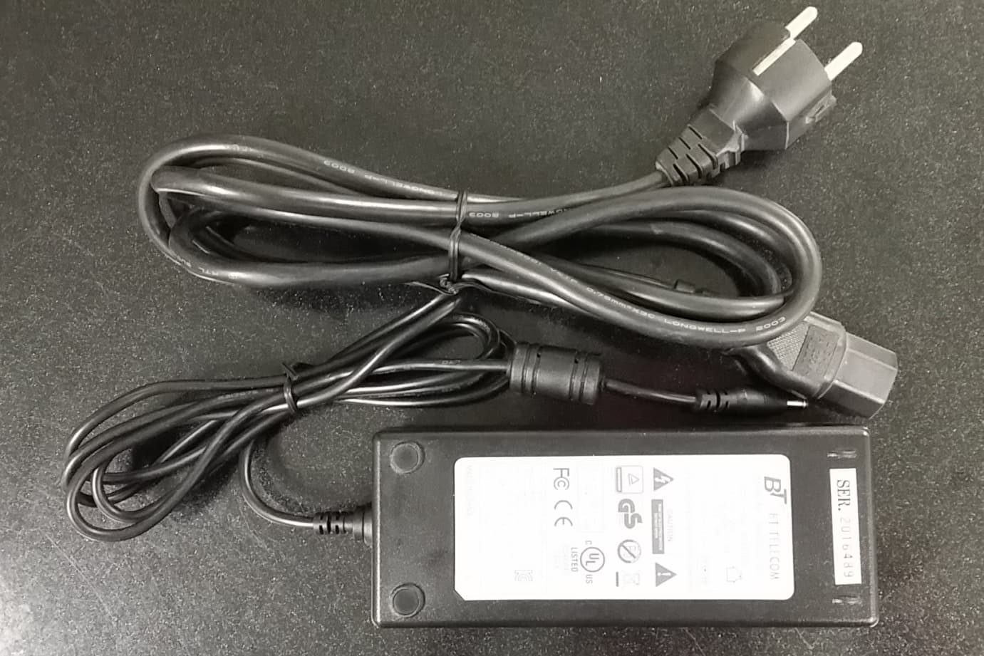
OPISYS Incorporated In Vehicle Dual Band Booster AVHR-5000N It should not be reproduced in full or partly without the written approval by TCL of RAPA. Testing and Certification Laboratory Appendix 3. External Photos of EUT 1. Top OPISYS Incorporated In Vehicle Dual Band Booster AVHR-5000N It should not be reproduced in full or partly without the written approval by TCL of RAPA. Testing and Certification Laboratory Appendix 3. External Photos of EUT 2. Bottom OPISYS Incorporated In Vehicle Dual Band Booster AVHR-5000N It should not be reproduced in full or partly without the written approval by TCL of RAPA. Testing and Certification Laboratory Appendix 3. External Photos of EUT 3. Front 4. Back 5. Right 6. Left OPISYS Incorporated In Vehicle Dual Band Booster AVHR-5000N It should not be reproduced in full or partly without the written approval by TCL of RAPA. Testing and Certification Laboratory Appendix 3. External Photos of EUT 7. Adapter
ID Label/Location Info
OPISYS Incorporated In Vehicle Dual Band Booster AVHR-5000N It should not be reproduced in full or partly without the written approval by TCL of RAPA. Testing and Certification Laboratory Appendix 2. FCC ID Label and Location
Internal Photos
OPISYS Incorporated In Vehicle Dual Band Booster AVHR-5000N It should not be reproduced in full or partly without the written approval by TCL of RAPA. Testing and Certification Laboratory Appendix 4. Internal Photos of EUT 1. Internal Top Side Bottom Side OPISYS Incorporated In Vehicle Dual Band Booster AVHR-5000N It should not be reproduced in full or partly without the written approval by TCL of RAPA. Testing and Certification Laboratory Appendix 4. External Photos of EUT 2. Top of Internal PCB ① ② ③ ④ OPISYS Incorporated In Vehicle Dual Band Booster AVHR-5000N It should not be reproduced in full or partly without the written approval by TCL of RAPA. Testing and Certification Laboratory Appendix 4. External Photos of EUT 3. Left – Top 4. Right - Top ① ② OPISYS Incorporated In Vehicle Dual Band Booster AVHR-5000N It should not be reproduced in full or partly without the written approval by TCL of RAPA. Testing and Certification Laboratory Appendix 4. External Photos of EUT 5. Left – Bottom 6. Right - Bottom ③ ④ OPISYS Incorporated In Vehicle Dual Band Booster AVHR-5000N It should not be reproduced in full or partly without the written approval by TCL of RAPA. Testing and Certification Laboratory Appendix 4. External Photos of EUT 7. Bottom of Internal PCB ① ② ③ ④ OPISYS Incorporated In Vehicle Dual Band Booster AVHR-5000N It should not be reproduced in full or partly without the written approval by TCL of RAPA. Testing and Certification Laboratory Appendix 4. External Photos of EUT 8. Left – Top 9. Right – Top ① ② OPISYS Incorporated In Vehicle Dual Band Booster AVHR-5000N It should not be reproduced in full or partly without the written approval by TCL of RAPA. Testing and Certification Laboratory Appendix 4. External Photos of EUT 10. Right – Top 11. Right - Bottom ③ ④
Test Report
Page : 1 / 131 Report No. : RAPA14-O-017 It should not be reproduced in full or partly without the written approval by TCL of RAPA. FCC CFR Part 20 (Rev 2.0) Testing and Certification Laboratory TEST REPORT Report Number RAPA14-O-017 Type of Equipment In-Vehicle Dual Band Booster Model Name AVHR-5000N FCC ID Q4EAVHR-5000N Applicant Name OPISYS Incorporated Logo Address 511. South Harbor Blvd. Unit P. La Habra, CA. 90631, United States Manufacturer Name Ace Technology Corp. Address 24BL 5L, 451-4, Nonhyeon-dong, Namdong-gu, Incheon, 405-849, Korea Test duration April 01, 2014 to September 19, 2014 Date of issue September 19, 2014 Total Page 131 pages (including this page) SUMMARY The equipment complies with FCC CFR 47 Part 20. This test report contains only the results of a single test of the sample supplied for the examination. It is not a general valid assessment of the features of the respective products of the mass-production. September 22, 2014 September 22, 2014 Tested by Hyun Soo Lee Reviewed by Sukil Park Manager Executive Managing Director TCL of RAPA TCL of RAPA Page : 2 / 131 Report No. : RAPA14-O-017 It should not be reproduced in full or partly without the written approval by TCL of RAPA. FCC CFR Part 20 (Rev 2.0) Testing and Certification Laboratory Test Report Revision History Revision Date Revised By Reason for Revision 1.0 April 14, 2014 Hyun Soo Lee Original Document 2.0 September 19, 2014 Hyun Soo Lee EUT Specific Revision -DL Gain : 50 dB → 48 dB -UL Gain : 50 dB → 48 dB -DL Output : +10 dBm → +5 dBm Page : 3 / 131 Report No. : RAPA14-O-017 It should not be reproduced in full or partly without the written approval by TCL of RAPA. FCC CFR Part 20 (Rev 2.0) Testing and Certification Laboratory CONTENTS 1. General description of EUT .............................................................................................................................. 4 1.1 Applicant ......................................................................................................................................................... 4 1.2 Manufacturer .................................................................................................................................................. 4 1.3 Basic description of EUT ................................................................................................................................ 4 1.4 Electrical specification .................................................................................................................................... 5 1.5 Mechanical specification ................................................................................................................................ 6 1.6 Environmental specification ........................................................................................................................... 6 1.7 AC/DC adaptor specification .......................................................................................................................... 6 2. General information of test ............................................................................................................................... 7 2.1 Test standards and results ............................................................................................................................. 7 2.3 Test configuration ........................................................................................................................................... 7 3. Measurement data ............................................................................................................................................. 8 3.1 Authorized frequency band verification .......................................................................................................... 8 3.2 Maximum power measurement ...................................................................................................................... 14 3.3 Maximum booster gain computation ............................................................................................................... 28 3.4 Intermodulation product ................................................................................................................................. 30 3.5 Out of band emission ..................................................................................................................................... 36 3.6 Conducted spurious emission ........................................................................................................................ 67 3.7 Noise limit ..................................................................................................................................................... 74 3.8 Uplink inactivity ............................................................................................................................................ 88 3.9 Variable booster gain ................................................................................................................................... 92 3.10 Occupied bandwidth .................................................................................................................................. 95 3.11 Oscillation detection ................................................................................................................................... 109 3.12 Radiated spurious emission ..................................................................................................................... 120 4. RF exposure statement ................................................................................................................................. 127 4.1 Friis transmission formula .......................................................................................................................... 127 4.2 Information of Antenna ..........................................................…
Text truncated - open the document above for the full version.
Test Setup Photos
OPISYS Incorporated In Vehicle Dual Band Booster AVHR-5000N It should not be reproduced in full or partly without the written approval by TCL of RAPA. Testing and Certification Laboratory Appendix 1. Photos of Test Setup 1. Test Setup of Radiation
Contact Information
Applicant
Jason Kim
Test Firm
TCL of RAPAWoong Gul Kang
[email protected]82-31-427-9100
Technical Specifications
| # | Rule Parts | Frequency Range | Power Output | Emission | Tolerance |
|---|---|---|---|---|---|
| 16 | 24E | 1.93 GHz - 1.99 GHz | 2.20 mW | G7D | Amp |
Other Applications from OPISYS Incorporated
Q4EUSHR-781921-5B
Mar 01, 20154G 5-Band Repeater Model Name-USHR-781921-5B
Equipment Class
B2W - Part 20 Wideband Consumer Booster (CMRS)
Q4EUSHR-0819L
Oct 26, 2012Dual Band Repeater
Equipment Class
PCB - PCS Licensed Transmitter
Q4EAVHR-5000
Apr 13, 2011Dual Band Repeater (Model: AVHR-5000)
Equipment Class
PCB - PCS Licensed Transmitter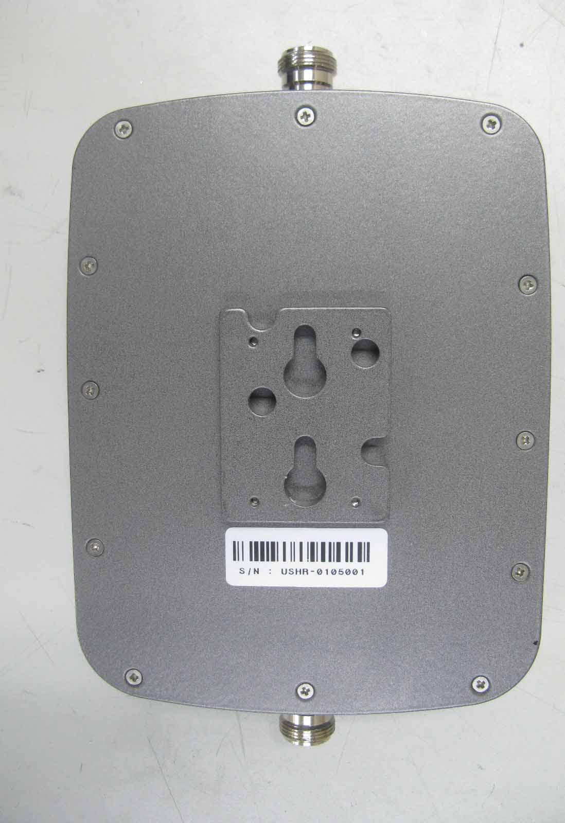
Q4EUSHR-0819SS
Mar 17, 2010Dual Band CDMA Repeater
Equipment Class
AMP - Amplifier
Q4EUSHR-800NIH
Jun 09, 2005iDEN Bi-Directional Amplifier
Equipment Class
AMP - Amplifier