Q4EUSHR-800NIHiDEN Bi-Directional Amplifier
OPISYS Incorporated
Click to zoom
Application Details
- Equipment Class
- AMP - Amplifier
- Date of Grant
- Jun 09, 2005
- Application Purpose
- Original Equipment
- Date of Application
- Jun 09, 2005
- Equipment Note
- iDEN Bi-Directional Amplifier
- Frequency Range
- 851.00000000 - 866.00000000
- Company
- OPISYS Incorporated
- Country
- United States
Documents & Files
Document Text
Text extracted from the exhibit documents filed with the FCC. Open a document above to read the original.
Users Manual
OPISYS USHR-800NIH Installation and Operations Manual 03/2005 OPISYS, INC. 9201 Irvine blvd Irvine, California Tel: (949) 916 5283 Fax: (949) 916 5285 Email: [email protected] Web: www.opisys.com 2 Table of Contents 1. General Information 1.1 Introduction 1.2 Specifications 1.3 Description 2 Installation 2.1 Introduction 2.2 Unpacking and Inspection 2.3 Preparation for Use 2.4 Before Installation 2.5 Antenna Installation 2.6 Bi-directional amplifier Installation 2.7 Connectors 2.8 Installation Example 3 Operation 3.1 Introduction 3.2 Operating Instructions 4 Trouble Shooting 5 Drawings 3 1. General Information 1.1 Introduction This manual provides information pertaining to the installation and operation of OPISYS’s USHR-800NIH “Ultra Slim Home” bi-directional amplifiers. This unit is for iDEN modulations in the below frequencies as shown in Table 1-1. <Table 1-1: USHR-800NIH Bi-directional amplifier > Model Number Down Link* Frequencies Up Link** Frequencies Modulation USHR-800NIH 851 ~ 866 MHz 806 ~ 821 MHz iDEN *: Down Link (= Forward Path) is from base station to mobile **: Up Link ( = Reverse Path) is from mobile to base station 4 1.2 Specifications <Table 1-2: USHR-800NIH Specifications> Item Specifications Down link 851 ~ 866 MHz Frequency Range Up link 806 ~ 821 MHz Down link +12dBm/Total Output Power Up link +12dBm/Total Down link Gain Up link 65 dB Down link Shutdown level Up link +14dBm/Total Down link ALC Range Up link 25dB Ripple < 7dB Propagation Delay < 1us Noise Figure < 7dB VSWR < 1.8 : 1 P1dB +24 dBm Output IP3 +40 dBm Frequency Stability ≤ ±0.05ppm In/Out Connector N Female Input Voltage AC/DC Adaptor , DC 5 V/ 1.2 A Dimensions (L*W*H, inch) 4.7” x 5.3” x 2.3” Weight ( Pound) 3.1 lb 5 1.3 Description This product is designed for offices, hotel rooms, small parking lots, garages or small buildings, helping to improve communications signal and coverage by extending the coverage of a base station. Outdoor antenna receives from a base station, then USHR-800NIH bi-directional amplifier amplifies the signal. After amplification, the signal is passed through to the indoor antennas. Conversely, signals from handsets are amplified and retransmitted to the base station. 2. Installation 2.1 Introduction This section provides information for the installation and setup of the USHR- 800NIH bi-directional amplifier. The information consists of procedures for unpacking, inspection and preparation for the installation, as well as the actual installation and the setup. 2.2 Unpacking and Inspection Examine the shipping carton for damage before unpacking the unit. If the shipping carton is damaged, try to have the carrier’s agent present when the equipment is unpacked. If visual inspection reveals physical damage(s) to the equipment, you should send it back for replacement. Verify that the equipment is complete, as listed under packing slip. Contact OPISYS with any missing component. 2.3 Preparation for Use 2.3.1 Power Requirements The power supply of the USHR-800NIH accepts 5 VDC. Power consumption of the USHR-800NIH is approximately 4.2 Watts. 2.3.2 Operating Environment The USHR-800NIH is intended for indoor use only. Do not install it where it might be exposed to the outside elements as this could result in destruction of the unit and other hazards. For normal operations, the environmental conditions should be as follow: Temperature range: –20 °C to 50 °C, Maximum Humidity: 95 % 6 2.4 Before Installation You will need to determine the following before beginning the USHR-800NIH installation: a. Base station location b. Location where the outdoor antenna is to be installed c. Location where the indoor antenna is to be installed d. Location where the USHR-800NIH is to be installed e. Length and type of coaxial cable needed to connect from the outdoor antenna to the bi-directional amplifier unit f. Length and type of coaxial cable needed to connect from the bi-directional amplifier unit to the indoor antenna 2.5 Antenna Installation 2.5.1 Outdoor Antenna Select a site for your outdoor antenna, making sure you have enough signal strength at that location. Using coax cable, connect the antenna to the bi-directional amplifier. If you are using a directional antenna such as a Yagi type, the antenna should be installed so that it is in line of sight of the base station. Then, align the directional antenna toward that direction, and secure the antenna using provided mounting hardware. Use of a lightning arrester is highly recommended. By installing a lightning arrester between the outside antenna and the bi-directional amplifier, you can protect the bi-directional amplifier unit from electrical surge from lightning. 2.5.2 Indoor Antenna Install the indoor antenna at a convenient location. It should be free of metallic obstruction in order to have an effective coverage. Depending on the circumstance of the installation, either one or a combination of following antennas can be used: Ceiling mount patch antenna, Wall mount patch antenna, Corner reflector 2.6 Bi-directional amplifier Installation USHR-800NIH is an indoor bi-directional amplifier. Accordingly, the environment of the intended installation site needs to be considered. The bi-directional amplifier must be shielded from moisture, such as rain, and excessive temperatures. The operating temperatures should be between -20 °C and 50 °C. 7 2.6.1 Turn-On Procedure Verify all RF connectors are tightened and cables and antennas are secured. Connect AC/DC Adaptor on the bi-directional amplifier’s DC IN connector. Turn on the Power Switch. The Power indicator LED should be green. Make sure that no other LED is illuminated. If any other LED is lit, consult the trouble shooting page of this manual, or “2.6.2 Antenna Isolation and Alignment” section. 2.6.2 Antenna Isolation and Alignment USHR-800NIH is equipped with an over drive protection circuit. If the output power level of reverse path(=Up Link) exceeds prescribed limit, then reverse path is discon…
Text truncated - open the document above for the full version.
Cover Letter(s)
9201 Irvine Blvd Irvine, CA 92618 Tel: 949 916 6244 Fax: 949 916 5285 May 17 2005 Federal Communications Commission Authorization and Evaluation Division Confidentiality Request regarding application for certification of FCC ID: Q4EUSHR-800NIH Pursuant to Sections 0.457 and 0.459 of the Commission’s Rules, we hereby request confidential treatment of information accompanying this application as outlined below: Part list, schematics, and block diagrams The above materials contain trade secrets and proprietary information not customarily released to the public. The public disclosure of these materials may be harmful to the applicant and provide unjustified benefits to its competitors. The applicant understands that pursuant to Section 0.457 of the Rules, disclosure of this application and all accompanying documentation will not be made before the date of the Grant for this application. Sincerely, Daniel Chun Director Opisys, Inc.
External Photos
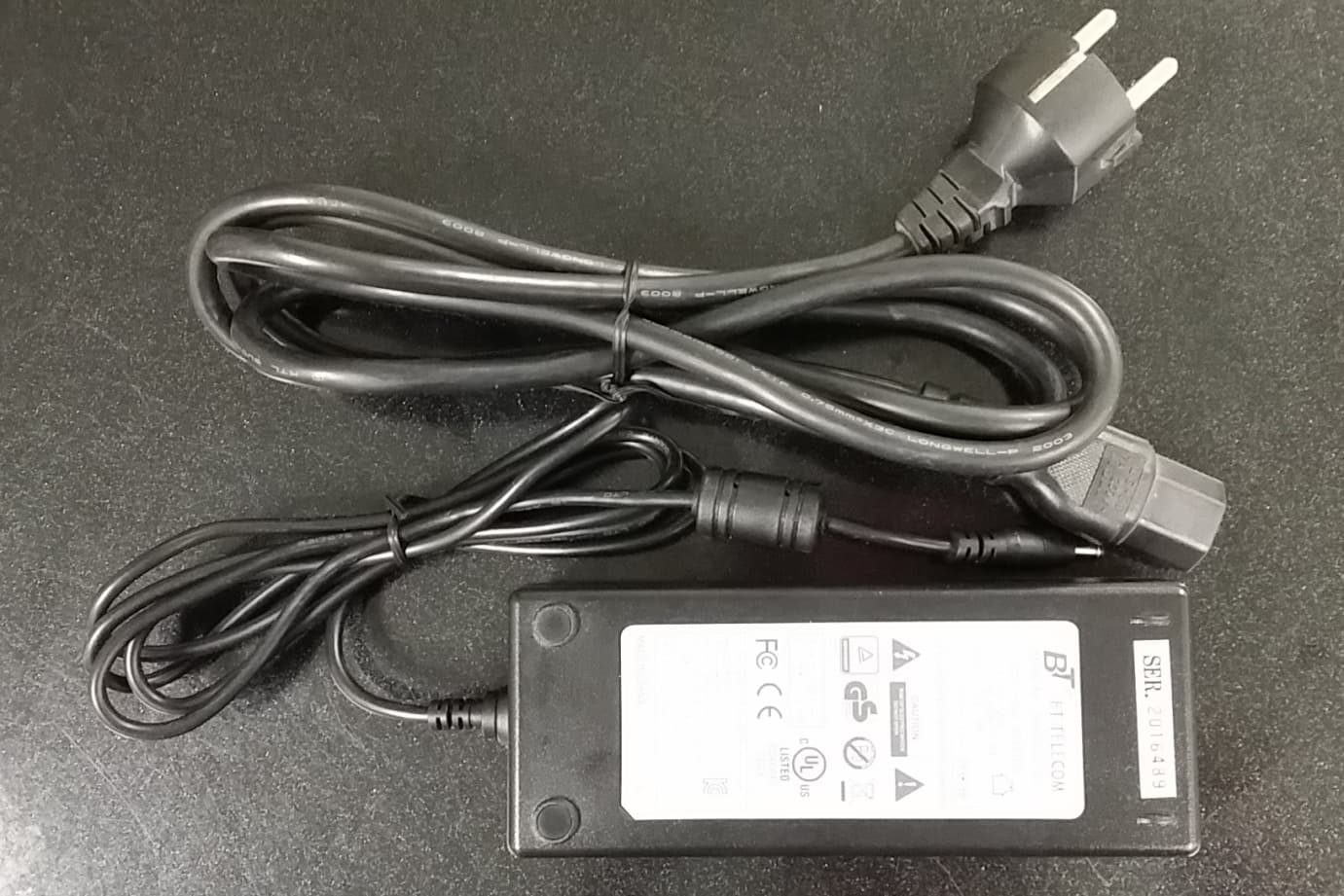
APPENDIX C - EUT EXTERNAL PHOTOGRAPHS EUT – Front View EUT – Rear View EUT – RF Port View EUT – DC Power Port View Power Adapter View I Power Adapter View II
ID Label/Location Info
APPENDIX A - FCC ID LABELING AND LOCATION Proposed FCC ID Labeling Proposed FCC ID Location Rear View of EUT / Proposed Label Location FCC ID: Q4EUSHR-800NIH
Internal Photos
APPENDIX C - EUT INTERNAL PHOTOGRAPHS Chassis – Cover off View EUT – Component View I EUT – Component View II EUT – Solder View I EUT – Solder View II EUT – Component Shielding Off View I EUT – Component Shielding Off View II
Operational Description
1 Model :USHR-800NIH Bi-directional Amplifier’s Technical Description April-18-2005 OPISYS, INC. 9201 Irvine blvd Irvine, California Tel: (949) 916 5283 Fax: (949) 916 5285 Email: [email protected] Web: www.opisys.com 2 FCC Part 2.983(d) Technical Description (d)(1) Type or types of emission iDEN (d)(2) Frequency Range Forward : 851 - 866 MHz Reverse : 806 - 821 MHz (d)(3) Range of Operating Power Levels, and description of any means provided for variation of operating power - 53 dBm to + 12dBm ( 15.8 mW) (Gain : 65 dB) (d)(4) Maximum power rating as defined in the applicable parts of the FCC rules 90.635(a) : The effective radiated power for base stations used in suburban-conventional systems of communications shall be no greater than 500 Watts ( 27 dBw) . 90.635(d) : Mobile/Portable stations are limited to 100 Watts (20 dBw ). (d)(5) The dc voltages applied to and dc currents into the several elements of the final radio frequency amplifying device for normal operation over the power range 5 VDC at 150 mA on A1 and A7 (d) (6) Function of each electron tube or semiconductor or other active circuit device Refer to Attachment : Data Sheet (d)(7) Complete circuit diagram Refer to Attachment : Circuit Diagram 3 (d)(8) Instruction books or installation manual Refer to Attachment : Installation and Operations Manual (d) (9) Tune-up procedure over the power range, or at specific operating power levels Refer to Attachment : Installation and Operations Manual (d)(10) A description of all circuitry and devices provided for determining and stabilizing frequency N/A (d)(11) A description of any circuits or devices employed for suppression of spurious radiation Duplexer : F2, F5 Band Pass Filters : F1, F6 SAW Filters : F3, F4 (d)(11) A description of any circuits or devices employed for limiting modulation N/A (d)(11) A description of any circuits or devices employed for limiting power If the output power level of reverse path(=Up Link) exceeds prescribed limit, then reverse path is disconnected and the RX Alarm LED is on. Bi-directional amplifier automatically checks output power level every one minute of a 5 minute cycle when reverse path has over power . If reverse path still exceeds level then shut down mode continues for another 10 minutes. After 10 minutes, reverse path is switched on again and it checks output power level again. (Repeats the process) Forward path procedure is same as reverse path except TX Alarm LED. (d)(12) For equipment employing digital modulation techniques, a detailed description of the modulation of the modulation system to be used, including the response characteristics 4 ( Frequency, phase, and amplitude) of any filters provided, and a description of the modulating wavetrain, shall be submitted for the maximum rated conditions under which the equipment will be operated. N/A (e) The data required by 2.985 through 2.997, inclusive, measured in accordance with the procedures set out in 2.999 **** Provided by FCC Approval Company after the tests. **** (f) A photograph or drawing of the equipment identification plate or label showing the information to be placed thereon. **** Provided by FCC Approval Company after the tests. **** (g) E.U.T 8 x 10 photographs **** Provided by FCC Approval Company after the tests. ****
RF Exposure Info
§1.1310 and §2.1091 - RF EXPOSURE According to §1.1307, systems operating under the provisions of this section shall be operated in a manner that ensures that the public is not exposed to radio frequency energy level in excess of the Commission’s guidelines. According to §1.1310 and §2.1091 RF exposure is calculated. Limits for General Population/Uncontrolled Exposure Frequency Range (MHz) Electric Field Strength (V/m) Magnetic Field Strength (A/m) Power Density (mW/cm 2 ) Averaging Time (minute) Limits for General Population/Uncontrolled Exposure 0.3-1.34 614 1.63 *(100) 30 1.34-30 824/f 2.19/f *(180/f 2 ) 30 30-300 27.5 0.073 0.2 30 300-1500 / / f/1500 30 1500-100,000 / / 1.0 30 f = frequency in MHz * = Plane-wave equivalent power density MPE Prediction Predication of MPE limit at a given distance Equation from page 18 of OET Bulletin 65, Edition 97-01 S = PG/4πR² Where: S = power density P = power input to antenna G = power gain of the antenna in the direction of interest relative to an isotropic radiator R = distance to the center of radiation of the antenna Uplink: Maximum peak output power at antenna input terminal: 11.93 (dBm ) Maximum peak output power at antenna input terminal: 15.60 (mW) Prediction distance: 20 (cm) Predication frequency: 815 (MHz) Antenna Gain (typical): 20 (dBi) antenna gain: 100 (numeric) Power density at predication frequency at 20 cm: 0.31 (mW/cm 2 ) MPE limit for uncontrolled exposure at prediction frequency: 0.54 (mW/cm 2 ) Downlink: Maximum peak output power at antenna input terminal: 12.15 (dBm ) Maximum peak output power at antenna input terminal: 16.41 (mW) Prediction distance: 20 (cm) Predication frequency: 860 (MHz) Antenna Gain (typical): 20 (dBi) antenna gain: 100 (numeric) Power density at predication frequency at 20 cm: 0.33 (mW/cm 2 ) MPE limit for uncontrolled exposure at prediction frequency: 0.57 (mW/cm 2 ) Test Result For Uplink, Its power density level at 20 cm is 0.31mW/cm², which is below the uncontrolled exposure limit of 0.54mW/cm² at 815 MHz. For Downlink, Its power density level at 20 cm is 0.33mW/cm², which is below the uncontrolled exposure limit of 0.57mW/cm² at 860 MHz.
Test Report
Note: The test report is specially limited to the above company and this particular sample only. It may not be duplicated without prior written consent of Bay Area Compliance Laboratory Corporation. This report must not be used by the client to claim product certification, approval, or endorsement by NVLAP, NIST or any agency of the US Government. FCC PART 90 TYPE APPROVAL EMI MEASUREMENT AND TEST REPORT For OPISYS Incorporated 9201 Irvine Blvd. Irvine, CA 92618 FCC ID: Q4EUSHR-800NIH This Report Concerns: Original Report Equipment Type: iDEN Bi-directional Amplifier Test Engineer: Daniel Deng Report No.: R0505164 Report Date: 2005-05-27 Reviewed By: Richard Lee Prepared By: Bay Area Compliance Laboratory Corporation 230 Commercial Street Sunnyvale, CA 94085 Tel: (408) 732-9162 Fax: (408) 732 9164 OPISYS Incorporated FCC ID: Q4EUSHR-800NIH Report # R0505164Rpt-aRpt-a Page 2 of 31 FCC Part 90 Type Approval Report TABLE OF CONTENTS GENERAL INFORMATION.......................................................................................................................................4 PRODUCT DESCRIPTION FOR EQUIPMENT UNDER TEST (EUT) ....................................................................................4 OBJECTIVE...................................................................................................................................................................4 RELATED SUBMITTAL(S)/GRANT(S).............................................................................................................................4 TEST METHODOLOGY..................................................................................................................................................4 TEST FACILITY.............................................................................................................................................................4 SYSTEM TEST CONFIGURATION ..........................................................................................................................5 JUSTIFICATION.............................................................................................................................................................5 BLOCK DIAGRAM.........................................................................................................................................................5 EQUIPMENT MODIFICATIONS.......................................................................................................................................5 LOCAL SUPPORT EQUIPMENT.......................................................................................................................................5 INTERFACE PORTS AND CABLE IN................................................................................................................................5 TEST SETUP BLOCK DIAGRAM.....................................................................................................................................5 SUMMARY OF TEST RESULTS ...............................................................................................................................6 §2.1046, AND §90.205 - CONDUCTED OUTPUT POWER .....................................................................................7 PROVISION APPLICABLE...............................................................................................................................................7 TEST PROCEDURE........................................................................................................................................................7 TEST EQUIPMENT.........................................................................................................................................................7 ENVIRONMENTAL CONDITIONS....................................................................................................................................7 TEST RESULTS.............................................................................................................................................................7 §2.1049, § 90.209, § 90.210 – OCCUPIED BANDWIDTH .........................................................................................8 APPLICABLE STANDARD..............................................................................................................................................8 TEST PROCEDURE........................................................................................................................................................8 TEST EQUIPMENT.........................................................................................................................................................8 ENVIRONMENTAL CONDITIONS....................................................................................................................................9 TEST RESULTS.............................................................................................................................................................9 §2.1051 AND §90.210 - SPURIOUS EMISSIONS AT ANTENNA TERMINALS ................................................16 APPLICABLE STANDARD............................................................................................................................................16 TEST PROCEDURE......................................................................................................................................................16 TEST EQUIPMENT.......................................................................................................................................................16 ENVIRONMENTAL CONDITIONS..................................................................................................................................16 TEST RESULTS.........................................................................................................…
Text truncated - open the document above for the full version.
Contact Information
Applicant
Jason Kim
Test Firm
Bay Area Compliance LaboratoryJohn Chan
Technical Specifications
| # | Rule Parts | Frequency Range | Power Output | Emission |
|---|---|---|---|---|
| 2 | 9 | 851 MHz - 866 MHz | 16.40 mW | 25K0G7W |
Other Applications from OPISYS Incorporated
Q4EUSHR-781921-5B
Mar 01, 20154G 5-Band Repeater Model Name-USHR-781921-5B
Equipment Class
B2W - Part 20 Wideband Consumer Booster (CMRS)
Q4EAVHR-5000N
Oct 13, 2014InVehicle Dual Band Booster
Equipment Class
B2W - Part 20 Wideband Consumer Booster (CMRS)
Q4EUSHR-0819L
Oct 26, 2012Dual Band Repeater
Equipment Class
PCB - PCS Licensed Transmitter
Q4EAVHR-5000
Apr 13, 2011Dual Band Repeater (Model: AVHR-5000)
Equipment Class
PCB - PCS Licensed Transmitter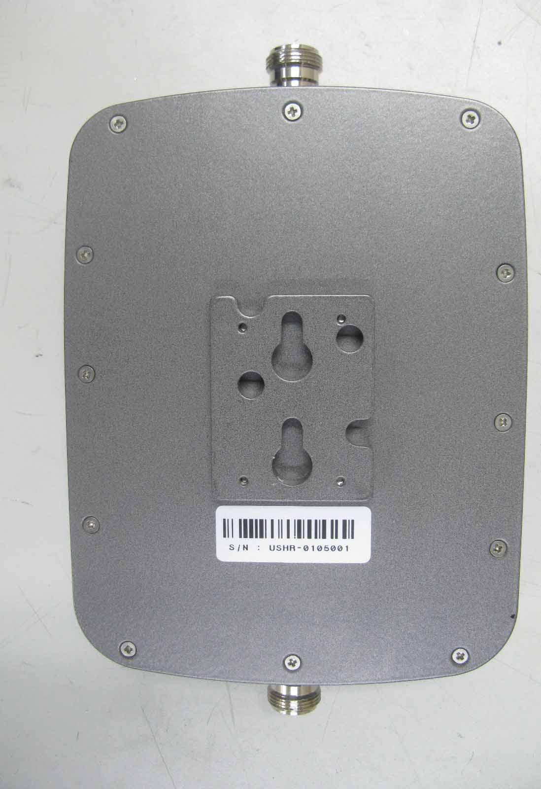
Q4EUSHR-0819SS
Mar 17, 2010Dual Band CDMA Repeater
Equipment Class
AMP - Amplifier