Q4EUSHR-0819LDual Band Repeater
OPISYS Incorporated
Click to zoom
Application Details
- Equipment Class
- PCB - PCS Licensed Transmitter
- Date of Grant
- Oct 26, 2012
- Application Purpose
- Original Equipment
- Date of Application
- Oct 26, 2012
- Equipment Note
- Dual Band Repeater
- Frequency Range
- 1930.20000000 - 1989.80000000
- Company
- OPISYS Incorporated
- Country
- United States
Documents & Files
Document Text
Text extracted from the exhibit documents filed with the FCC. Open a document above to read the original.
Users Manual
Users Guide & Installation Manual USHR-0819L Page 2 - Content - 1. General Information 2. System Components 3. Installation 4. Trouble Shooting 5. Specification 6. Certificates 7. Memo This device complies with Part 15 of the FCC Rules. Operation is subject to the following conditions; This device complies with the Industry Canada license-exempt RSS standard(s). Operation is subject to the following conditions; (1) This device may not cause harmful interference. (2) This device must accept any interference received, including interference that may cause undesired operation. CAUTION: Changes or modifications not expressly approved by the party responsible for compliance could void the user’s authority to operate this device. Statement : The term “IC” before the radio certification number only signifies that Industry Canada technical specifications were met. CAUTION : The User that modifications to the unit may void the user’s authority to operate this device. To maintain compliance with RF energy exposure guidelines, the antenna used for this transmitter must be maintained a separation distance of at least 20cm from the user body when transmitting. Co-located or operated in conjunction with any other antenna or transmitter is prohibited. Page 3 1. General Information 1.1. Precautions 1.1.1 Do not drop the device - It may damage the product and its function 1.1.2 Do not place near magnetic material - It may cause of possible malfunction 1.1.3 Product is recommended to be used with original AC/DC adapter 1.1.4 Install the product where it is recommended - It may not properly operate if it is not recommended location 1.1.5 Do not disassemble/ repair the product - Warranty may void once you disassemble the product. 1.1.6 Turn off the device immediately if a smog or any strange odor is detected from the product. 1.1.7 Use contained bolt to install on the wall. Make sure it is safely installed before operation Reference: Direction/Information for the proper operation Cautions: Information for users to avoid malfunctions Warning: Instruction for users to avoid unexpected hazard 1.2 . Features 1.2.1. Summary This device may be installed on residential area, office, warehouse etc. . Following is advantage of using in-building repeater system. This is RF type amplifier for Cellular800MHz and PCS1900MHz signal enhancement. It covers GSM, EDGE, CDMA, WCDMA mobile phone users. (Please refer repeater specification for operating Frequency Range info.) 1.2.2 . Features Page 4 I.Decrease dropped call rate II. Increase signal strength III. Improve Data / Voice quality IV. Prolong hand phone battery life V. Improve data Communication Rate I.Wider Coverage area - Gain 65dB . II. ALC(Automatic output Level Control) - Stabilize operation in any radio environment III. Fulfill IS-95A spurious specification at +15dBm output power - Provide high Data Communication Rate IV. Easy gain control by dip switch located on the front side of product V.Support dual band - enable to connect service from multiple carrier simultaneously - 800MHz / 1900MHz service simultaneously - 800MHz / 1900MHz adopt independent operation algorithm VI. Check status of product by LED indicator VII. Manage and control product by GUI(Graphic User Interface) - Please ask professional installer about GUI Program VIII. Enable to stay connected in homes and offices - Please ask professional installer for installation on homes & offices IX. GSM, EDGE, CDMA, WCDMA ready Page 5 ①Dual Band Repeater ②AC/DC Adapter ③User Manual 2. System components ④Installation bolts ① Dual band Repeater : BTS and mobile phone signal booster ② AC/DC Adaptor : 110V power supply ③ User Manual : Operation manual ④ Installation Bolts : Holds repeater on the vertical wall USHR-0819L Page 6 3. Installation 3.1. Installation diagram 3.2. Repeater Service ANT Port Donor ANT Port Cellular Status LED POWER LED Cellular Gain control Dip Switch PCS Gain control Dip Switch POWER Jack Port Power ON/OFF Switch PCS Status LED GUI PORT Installation Bracket 3.1.1. Install Donor Antenna on higher location to avoid any signal interference. 3.1.2. Install service antenna at appropriate location such as wall or roof ceiling. Make sure service antenna is not blocked by furniture or hope appliance. 3.1.3. Use enclosed bolt to fix repeater on the wall and plug in power adaptor. Page 7 3.3. Repeater and Antenna connection 3.3.1. Connect donor antenna to RVS connector as shown below. 3.3.2. Connect Service antenna to FWD connector as shown below. 3.3.3. Plug in power adaptor to power outlet. Page 8 3.3.4. Plug in AD/CD adaptor to connector listed as DC5.6V 3.3.5. Once power is on, it will show 3 green LED light on the front of product as shown below. Page 9 4.1.1. Power on status 4.1.2. Power off status 4.1.3. Cellular normal operation condition 4.1.4. During normal Cellular operation, it detects excessive input signal or it is under oscillation condition due to insufficient isolation between antennas 4.1.5. Due to excessive input signal or oscillation, it cut off circuit to protect hardware 4.1.6. PCS normal operation condition 4.1.7. During normal PCS operation, it detects excessive input signal or it is under oscillation condition due to insufficient isolation between antennas 4.1.8. Due to excessive input signal or oscillation, it cut off circuit to protect hardware 4. Trouble Shooting 4.1. LED Status ItemGREEN LEDRED LED Problem Reference PWR ON-See 4.1.1 OFFOFFSee 4.1.2 Cellular ON-See 4.1.3 -ONSee 4.1.4 OFFOFFSee 4.1.5 PCS ON-See 4.1.6 -ONSee 4.1.7 OFFOFFSee 4.1.8 Page 10 ItemSpecificationsNote Operating Frequency Down Link1930 ~ 1990 MHz PCS1900 BW: 60MHz Up Link1850 ~ 1910 MHz Down Link869 ~ 894 MHz Cellular800 BW: 25 MHz Up Link824 ~ 849 MHz Modulation TypeGSM, EDGE, CDMA, WCDMA Input Power-28dBm max Output Power Down Link+12dBm PCS1900 Up Link+15dBm Down Link+12dBm Cellular800 Up Link+15dBm Gain Down Link65dB (±1.0dB) PCS1900, Average Gain on 60MHz BW Up Link65dB (±1.0dB) Down Link65dB…
Text truncated - open the document above for the full version.
Cover Letter(s)
Date: October 8, 2012 Federal Communications Commission 7435 Oakland Mills Road Columbia MD 21046 c.c. Compliance Certification Services Certification Division 47173 Benicia Street Fremont, CA 94538, USA To whom it may concern: I, the undersigned, hereby authorize Mr. CY_Choi/ RAPA, to act on our behalf in all manners relating to application for equipment authorization, including signing of all documents relating to these matters. Any and all acts carried out by Mr. CY_Choi / RAPA on our behalf shall have the same effect as acts of our own. I, the undersigned, hereby certify that we are not subject to a denial of federal benefits, that includes FCC benefits, pursuant to Section 5301 of the Anti-Drug Abuse Act of 1988, 21 U.S.C. 853(a). In authorizing UL Korea as our agent, we still recognize that we are responsible to: a) comply with the relevant provisions of the certification program; b) make all necessary arrangements for the conduct of the evaluation, including provision for examining documentation and access to all areas, records (including internal audit reports) and personnel for the purposes of evaluation (e.g. testing, inspection, assessment, surveillance, reassessment) and resolution of complaints; c) make claims regarding certification only in respect of the scope for which certification has been granted; d) do not use our product certification in such a manner as to bring the Certification Division into disrepute and not make any statement regarding our product certification which the Certification Division may consider misleading or unauthorized; e) upon suspension or cancellation of certification, discontinue use of all advertising matter that contains any reference thereto and return any certification documents as required by the Certification Division; f) use certification only to indicate the products are certified as being in conformity with specified standards; g) endeavor to ensure that no certificate or report nor any part thereof is used in a misleading manner; h) ensure that any reference to our product certification in communication media such as documents, brochures or advertising, complies with the requirements of the Certification Division; i) keep a record of all complaints made known to the us relating to the product’s compliance with requirements of the relevant standard and to make these records available to the Certification Division when requested; j) take appropriate action with respect to such complaints and any deficiencies found in products or services that affect compliance with the requirements for certification; k) document the actions taken. This authorization is valid until further written notice from the applicant. Sincerely Yours, REMARK: 1. This authorization letter will be sent along with your application when filing with the Certification Division. 2. Please follow the format and type it on company letterhead and send original to us. 3. Authorized signature must be in agreement with grantee code contact in FCC database.
Cover Letter(s)
OPISYS Incorporated 590 West Central Ave Unit E, Brea CA 92821, United States E-MAIL : [email protected] Federal Communications Commission 7435 Oakland Mills Road Columbia, MD 21046 Gentlemen: This letter is to comply with Section pertaining to confidential material OPISYS Incorporated would like the following documents regarding this submission for FCC ID : Q4EUSHR-0819L to be kept confidential. 1. Block Diagram 2. Schematic 3. Operational Description 4. Layout 5. Parts List The ab ove material contains trade secrets or technical data, which would customarily be guarded from competitors. We do not want these documents to be accessible to the general public. Sincerely, Date 8th of October , 2012 By Karen KH Koo
External Photos
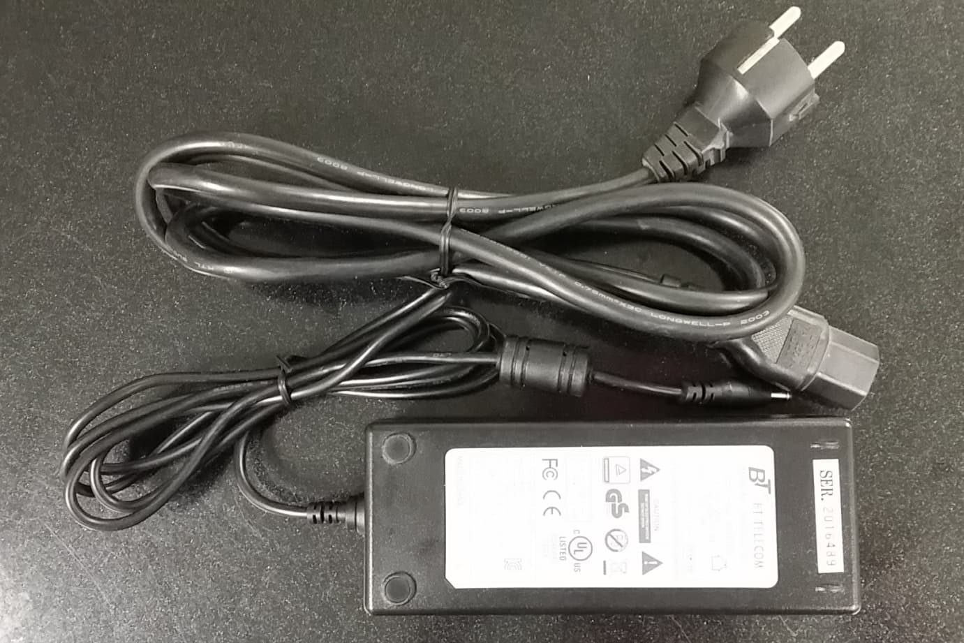
OPISYS Incorporated Dual Band Repeater USHR-0819L It should not be reproduced in full or partly without the written approval by TCL of RAPA. Testing and Certification Laboratory Appendix 3. External Photos of EUT 1. Top OPISYS Incorporated Dual Band Repeater USHR-0819L It should not be reproduced in full or partly without the written approval by TCL of RAPA. Testing and Certification Laboratory Appendix 3. External Photos of EUT 2. Bottom OPISYS Incorporated Dual Band Repeater USHR-0819L It should not be reproduced in full or partly without the written approval by TCL of RAPA. Testing and Certification Laboratory Appendix 3. External Photos of EUT 3. Front 4. Back 5. Right 6. Left OPISYS Incorporated Dual Band Repeater USHR-0819L It should not be reproduced in full or partly without the written approval by TCL of RAPA. Testing and Certification Laboratory Appendix 3. External Photos of EUT 7. Adapter
ID Label/Location Info
OPISYS Incorporated Dual Band Repeater USHR-0819L It should not be reproduced in full or partly without the written approval by TCL of RAPA. Testing and Certification Laboratory Appendix 2. FCC ID Label and Location
Internal Photos
OPISYS Incorporated Dual Band Repeater USHR-0819L It should not be reproduced in full or partly without the written approval by TCL of RAPA. Testing and Certification Laboratory Appendix 4. Internal Photos of EUT 1. Internal OPISYS Incorporated Dual Band Repeater USHR-0819L It should not be reproduced in full or partly without the written approval by TCL of RAPA. Testing and Certification Laboratory Appendix 4. External Photos of EUT 2. Top of Internal PCB ① ② ③ ④ OPISYS Incorporated Dual Band Repeater USHR-0819L It should not be reproduced in full or partly without the written approval by TCL of RAPA. Testing and Certification Laboratory Appendix 4. External Photos of EUT 3. Left – Top 4. Right - Top ① ② OPISYS Incorporated Dual Band Repeater USHR-0819L It should not be reproduced in full or partly without the written approval by TCL of RAPA. Testing and Certification Laboratory Appendix 4. External Photos of EUT 5. Left – Bottom 6. Right - Bottom ③ ④ OPISYS Incorporated Dual Band Repeater USHR-0819L It should not be reproduced in full or partly without the written approval by TCL of RAPA. Testing and Certification Laboratory Appendix 4. External Photos of EUT 7. Bottom of Internal PCB ① ② ③ ④ OPISYS Incorporated Dual Band Repeater USHR-0819L It should not be reproduced in full or partly without the written approval by TCL of RAPA. Testing and Certification Laboratory Appendix 4. External Photos of EUT 8. Left – Top 9. Right – Top ① ② OPISYS Incorporated Dual Band Repeater USHR-0819L It should not be reproduced in full or partly without the written approval by TCL of RAPA. Testing and Certification Laboratory Appendix 4. External Photos of EUT 10. Right – Top 11. Right - Bottom ③ ④ OPISYS Incorporated Dual Band Repeater USHR-0819L It should not be reproduced in full or partly without the written approval by TCL of RAPA. Testing and Certification Laboratory Appendix 4. External Photos of EUT 12. Top of LED PCB 13. Bottom of LED PCB
Parts List/Tune Up Info
Tune-up Procedure 1. Test equipment & Accessory No Equipment Model Name Manufacturer 1 Signal Generator E4437B Agilent 2 Spectrum Analyzer N9020A Agilent 3 Network Analyzer ZVA 24 R&S 4 Attenuator 66-30-33 Weinschel 2. Cable No Cable Number Type Length 1 RAPA-C 09 N type – N type 1 m 2 RAPA-C 10 N type – N type 1 m 3. Test Configuration for USHR-0819L Link Band Max. Gain Min. Input Power Output Power Down Link Cellular 65 dB -53 dBm +12 dBm PCS Up Link Cellular -50 dBm +15 dBm PCS 4. Specification of EUT by Manufacturer - Next Page Date 2012.08.09 Sheet No. 1/4 Version No. 1.0 Written by S.O.Kang Checked by Confirmed by Authorized by Subject : USHR-0819L ACE technologies SPECIFICATION SHEET Model Name: USHR-0819L ACE TECHNOLOGIES Date 2012.08.09 Sheet No. 2/4 Version No. 1.0 Written by S.O.Kang Checked by Confirmed by Authorized by Subject : USHR-0819L ACE technologies Revised date Description Remarks 2012.08.09 Initial version Date 2012.08.09 Sheet No. 3/4 Version No. 1.0 Written by S.O.Kang Checked by Confirmed by Authorized by Subject : USHR-0819L ACE technologies 1. Electrical Specification Item Specifications Note Frequency Range Down Link 1930 ~ 1990 MHz PCS1900 BW: 60MHz Up Link 1850 ~ 1910 MHz Down Link 869 ~ 894 MHz Cellular800 BW: 25 MHz Up Link 824 ~ 849 MHz Modulation Type GSM, EDGE, CDMA, WCDMA Input Power -28dBm max Output Power Down Link +12dBm PCS1900 Up Link +15dBm Down Link +12dBm Cellular800 Up Link +15dBm Gain Down Link 65dB (±1.0dB) PCS1900, Average Gain on 60MHz BW Up Link 65dB (±1.0dB) Down Link 65dB (±1.0dB) Cellular800, Average Gain on 25MHz BW Up Link 65dB (±1.0dB) Gain Control Range 25dB could be changed Dip switch or GUI Ripple < 6.5dB PCS1900 < 4.5dB Cellular800 Noise Figure < 6dB typical PCS1900 Uplink Max Gain < 5dB typical Cellular800 Uplink Max Gain Propagation Delay 5us max PCS1900/ Cellular800 VSWR ≤ 1.8 : 1 PCS1900/ Cellular800 ALC Level Down Link +12dBm (±1dB) PCS1900/ Cellular800 Up Link +15dBm (±1dB) PCS1900/ Cellular800 Shutdown Level Down Link +14dBm (±1dB) PCS1900/ Cellular800 Up Link +17dBm (±1dB) PCS1900/ Cellular800 Spectrum Mask 750KHz -45dBc/30kHz Note1. Downlink CDMA 9CH Signal Note2. Uplink CDMA Reverse Signal 1.98MHz -50dBc/30kHz Spurious 9 ~ 150kHz -13dBm/30kHz 150kHz ~ 30MHz -13dBm/30kHz 30MHz ~ 1GHz -13dBm/30kHz 1GHz ~ 12.75GHz -13dBm/30kHz Frequency Stability ≤ ±0.01ppm PCS1900/ Cellular800 GUI Interface RS-232C Alarm & Status Display PWR Normal : Green, Pwr turn off : Off Cellular Normal : Green, Shutdown : Off, Checking SD : Red PCS Normal : Green, Shutdown : Off, Checking SD : Red Power Consumption 5.6Vdc / 1.7A Input Voltage DC 5.6Vdc / 2.5A AC/DC Adapter RF Connector N-type Female Date 2012.08.09 Sheet No. 4/4 Version No. 1.0 Written by S.O.Kang Checked by Confirmed by Authorized by Subject : USHR-0819L ACE technologies 2. Mechanical Specification Item Specifications Note Dimensions (L W H) 151mm x 191mm x 35mm (5.95 x 7.5 x 1.38 inch) Weight 2Kg 3. Environmental Specification Item Specifications Note Temperature -30 ~ 55°C(-22 ~ 131°F) Humidity 10 ~ 95% 4. Operating Functions This product has below serious functions. a. First function is ALC. ALC is an abbreviation for automatic level control. This function limit output power level that is changed by input signals. c. Third function is shutdown. This function is for protecting the booster. The booster would operate ALC function if input signal would be stronger signal then normal one. But if input signal would be over ALC range, Shutdown function will operation in this time. d. Fifth function is LED indicating status for booster got normal or abnormal. e. Sixth function is RS-232C. This function offers you to interface GUI. Therefore, User can set parameters of booster as interconnecting between laptop computer and booster.
RF Exposure Info
Page : 61 of 65 Report No. : RAPA12-O-630 It should not be reproduced in full or partly without the written approval by TCL of RAPA. FCC CFR Part 22H/24E(Rev.0) Testing and Certification Laboratory 4. RF exposure statement According to §1.1307, systems operating under the provisions of this section shall be operated in a manner that ensures that the public is not exposed to radio frequency energy level in excess of the Commission’s guidelines. According to §1.1310 and §2.1091 RF exposure is calculated. Limits for General Population/Uncontrolled Exposure Frequency Range [MHz] Electric Field Strength [V/m] Magnetic Field Strength [A/m] Power Density [mW/cm 2 ] Averaging Time [minute] Limits for General Population/Uncontrolled Exposure 0.3 – 1.34 614 1.63 100 30 1.34 – 30 824/f 2.19/f 180/f 2 30 30 – 300 27.5 0.073 0.2 30 300 – 1500 - - f/1500 30 1500 – 100 000 - - 1.0 30 ※f = frequency in MHz 4.1 Friis transmission formula P d = (P out X G) / (4πr 2 ) P d = Power density P out = power input to antenna G = power gain r = distance to the center of radiation of the antenna Page : 62 of 65 Report No. : RAPA12-O-630 It should not be reproduced in full or partly without the written approval by TCL of RAPA. FCC CFR Part 22H/24E(Rev.0) Testing and Certification Laboratory 4.2 Information of Antenna • Model Name : PAT-CPWI-M Antenna Gain; • 824 MHz – 894 MHz : 4 dBi • 1 750 MHz – 2 400 MHz : 7 dBi Page : 63 of 65 Report No. : RAPA12-O-630 It should not be reproduced in full or partly without the written approval by TCL of RAPA. FCC CFR Part 22H/24E(Rev.0) Testing and Certification Laboratory • Model Name : ALP-15QD-M Antenna Gain; • 824 MHz – 894 MHz : 5 dBi • 1 750 MHz – 2 400 MHz : 11 dBi Page : 64 of 65 Report No. : RAPA12-O-630 It should not be reproduced in full or partly without the written approval by TCL of RAPA. FCC CFR Part 22H/24E(Rev.0) Testing and Certification Laboratory 4.3 Calculation of MPE at 20 cm Band Link Frequency [MHz] Output power [dBm] Antenna gain [dBi] EIRP Power density [mW/cm 2 ] Limit [mW/cm 2 ] [dBm][mW] Cellular 800 Up Link 824.20 15.03 5.00 20.03100.690.020 042 0.549 467 836.60 15.01 5.00 20.01100.230.019 950 0.557 733 848.80 15.04 5.00 20.04100.930.020 089 0.565 867 Down Link 869.20 12.03 5.00 17.0350.470.010 045 0.579 467 881.60 12.03 5.00 17.0350.470.010 045 0.587 733 893.80 12.01 5.00 17.0150.230.009 999 0.595 867 PCS 1900 Up Link 1 850.2015.01 11.00 26.01399.020.079 424 1.000 000 1 880.0015.01 11.00 26.01399.020.079 424 1.000 000 1 909.8015.01 11.00 26.01399.020.079 424 1.000 000 Down Link 1 930.2012.02 11.00 23.02200.450.039 806 1.000 000 1 960.0012.01 11.00 23.01199.990.039 806 1.000 000 1 989.8012.03 11.00 23.03200.910.039 990 1.000 000 • Celluar 800 The maximum conducted power is 15.0 dBm; antenna is fix-mounted with a maximum gain of 5 dBi gain. Therefore, to comply with RF Exposure Requirement, the MPE is calculated. The maximum Peak EIRP calculated is 20.0 dBm. The Power Density can be calculated using the formula It is considered that 20 cm is the minimum distance that a user can go closer to the EUT. At 0.2 m, S = 0.02 mW/cm 2 , which is below the MPE Limit of 0.55 mW/cm 2 • PCS Band The maximum conducted power is 15.0 dBm; antenna is fix-mounted with a maximum gain of 11 dBi gain. Therefore, to comply with RF Exposure Requirement, the MPE is calculated. The maximum Peak EIRP calculated is 26 dBm. It is considered that 20 cm is the minimum distance that a user can go closer to the EUT. At 0.2 m, S = 0.08 mW/cm 2 , which is below the MPE Limit of 1.00 mW/cm 2
Test Report
Page : 2 of 65 Report No. : RAPA12-O-630 It should not be reproduced in full or partly without the written approval by TCL of RAPA. FCC CFR Part 22H/24E(Rev.0) Testing and Certification Laboratory CONTENTS 1.1 Applicant ................................................................................................................................................... 3 1.2 Manufacturer ............................................................................................................................................ 3 1.3 Basic description of EUT .......................................................................................................................... 3 1.4 Electrical specification .............................................................................................................................. 4 1.5 Mechanical specification .......................................................................................................................... 5 1.6 Environmental specification ..................................................................................................................... 5 2.1 Standard for measurement methods ....................................................................................................... 6 2.2 Description of EUT modification ............................................................................................................... 6 2.3 Test configuration ..................................................................................................................................... 6 3.1 RF power output ....................................................................................................................................... 7 3.2 Occupied bandwidth ............................................................................................................................... 10 3.3 Unwanted emission of antenna terminals .............................................................................................. 29 3.4 Field strength of spurious emission ....................................................................................................... 56 3.5 Amplifier gain and bandwidth ................................................................................................................. 58 4.1 Friis transmission formula ...................................................................................................................... 61 4.2 Information of Antenna ........................................................................................................................... 62 4.3 Calculation of MPE at 20 cm .................................................................................................................. 64 1. General description of EUT ........................................................................................................................... 3 2. General information of test ............................................................................................................................ 6 3. Measurement data .......................................................................................................................................... 7 4. RF exposure statement ................................................................................................................................ 61 5. Test equipment list ....................................................................................................................................... 65 Page : 3 of 65 Report No. : RAPA12-O-630 It should not be reproduced in full or partly without the written approval by TCL of RAPA. FCC CFR Part 22H/24E(Rev.0) Testing and Certification Laboratory 1. General description of EUT 1.1 Applicant • Company name : OPISYS Incorporated • Address : 590 West Central Ave Unit E, Brea CA 92821, United States • Contact person : Karen KH Koo • Phone/Fax : 1-714-990-6247/ 1-714-990-6243 1.2 Manufacturer • Company name : Ace Technology Corp. • Address : 24BL 5L, 451-4, Nonhyeon-dong, Namdong-gu, Incheon, 405- 849, Korea • Phone / Fax : 82-32-458-1382 / 82-32-458-1646 1.3 Basic description of EUT • Product name : Dual Band Repeater • Model name : USHR-0819L • Frequency : PCS 1900 / Downlink : 1 930 MHz – 1 990 MHz PCS 1900 / Uplink : 1 850 MHz – 1 910 MHz Cellular 800 / Downlink : 869 MHz – 894 MHz Cellular 800 / Uplink : 824 MHz – 849 MHz • Output power : Downlink : 12 dBm / Uplink : 15 dBm • Modulation method : GSM, EDGE, CDMA, WCDMA • FCC Rule Part(s) : FCC CFR47 Part 22H/24E • IC Rule Part(s) : IC RSS-131 Issue2 • FCC classification : PCB / PCS Licensed Transmitter • IC classification : Zone Enhancers for the Land Mobile Service • Test duration : September 10, 2012 to October 08, 2012 • Date of issue : October 08, 2012 • Place of test : Head office 824, B104, Anyang Megavalley, 799, Gwanyang-dong, Dongan-gu, Anyang-si, Gyeonggi-do, Korea, 483 -060 Open area test site 80, Jeil-ri, Yangji-myun, Cheoin-gu, Yongin-si, Gyeonggi-do, Korea, 449-825 (FCC Registration Number : 337229) (IC Submission Number : 143881) (KCC Designation Number : KR0027) Page : 4 of 65 Report No. : RAPA12-O-630 It should not be reproduced in full or partly without the written approval by TCL of RAPA. FCC CFR Part 22H/24E(Rev.0) Testing and Certification Laboratory 1.4 Electrical specification Item Specifications Note Frequency Range Down Link 1 930 ~ 1 990 MHz PCS1900 BW: 60 MHz Up Link 1 850 ~ 1 910 MHz Down Link 869 ~ 894 MHz Cellular800 BW: 25 MHz Up Link 824 ~ 849 MHz Modulation Type GSM, EDGE, CDMA, WCDMA Input Power -28 dBm max Output Power Down Link +12 dBm PCS1900 Up Link +15 dBm Down Link +12 dBm Cellular800 Up Link +15 dBm Gain Down Link 65 dB (±1.0 dB) PCS1900, Average Gain on 60 MHz BW Up Link 65 dB (±1.0 dB) Down Link 65 dB (±1.0 dB) Cellular800, Average Gain on 25 MHz BW Up Link 65 dB (±1.0 dB) Gain Control Range 25 dB could be changed D…
Text truncated - open the document above for the full version.
Contact Information
Applicant
Jason Kim
Test Firm
Testing and Certification Agency of RAPAWoong-gul Kang
Technical Specifications
| # | Rule Parts | Frequency Range | Power Output | Emission | Tolerance |
|---|---|---|---|---|---|
| 8 | 24E | 1.93 GHz - 1.99 GHz | 16.00 mW | F9W | Amp |
Other Applications from OPISYS Incorporated
Q4EUSHR-781921-5B
Mar 01, 20154G 5-Band Repeater Model Name-USHR-781921-5B
Equipment Class
B2W - Part 20 Wideband Consumer Booster (CMRS)
Q4EAVHR-5000N
Oct 13, 2014InVehicle Dual Band Booster
Equipment Class
B2W - Part 20 Wideband Consumer Booster (CMRS)
Q4EAVHR-5000
Apr 13, 2011Dual Band Repeater (Model: AVHR-5000)
Equipment Class
PCB - PCS Licensed Transmitter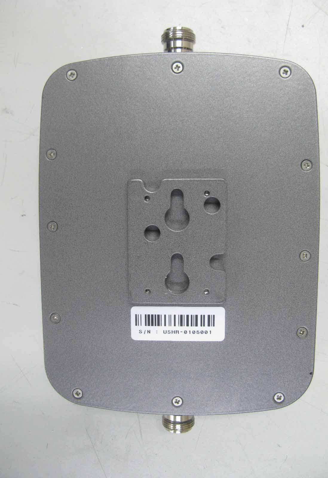
Q4EUSHR-0819SS
Mar 17, 2010Dual Band CDMA Repeater
Equipment Class
AMP - Amplifier
Q4EUSHR-800NIH
Jun 09, 2005iDEN Bi-Directional Amplifier
Equipment Class
AMP - Amplifier