Q54CDR-0200Smart Card Reader
S-1 Corporation
Click to zoom
Application Details
- Equipment Class
- DXX - Part 15 Low Power Communication Device Transmitter
- Date of Grant
- Jun 18, 2003
- Application Purpose
- Original Equipment
- Date of Application
- Jun 18, 2003
- Equipment Note
- Smart Card Reader
- Frequency Range
- 13.55300000 - 13.56700000
- Company
- S-1 Corporation
- Country
- South Korea
Documents & Files
Document Text
Text extracted from the exhibit documents filed with the FCC. Open a document above to read the original.
Users Manual
User's Manual For Smart Card Reader(CDR-0200) S1 CORPORATION Smart Card Reader(CDR-0200) Smart card reader is a machine controlling access management and making block mode change in GBMS. Power is supplied by auxiliary power equipment or local controllerII. lock controller. Access management function transmits the data to lock controller as it reads recorded data in card by the method of making customer or traverse card approach to card reader. Lock controller makes access available by controlling lock/auto door of entrance door after checking whether received data is registered or not. Mode change function transmits the data to lock controller as it reads recorded data in card by the method of making customer or traverse card approach to card reader keeping pushed SECOM button of smart card reader. Controller selects guard modes such as set/cancel/traverse by checking whether the received data is registered or not. Use Environment (1) Use temperature : -20°C ∼ +45°C (2) Use humidity : 30% ∼ 90%(relative humidity) (3) Installation requirements - Convenient Place for manipulating machine. - Install on none-metal. - Place which is not affected by raining. - Place which has not direct ray. - Place which is not affected by heat. - Place which has not vibration. - Install at the place that reading distance should be kept more than 5CM. Beep sound & Guiding voice Trough speaker, guiding voice is given as followings. And beep sends confirming sound. Guiding voice Standard Specifications * size : 95(W) × 140(H) × 28(D) 〔mm〕 * Weight : about 234g * Working voltage : DC 17.0 ∼ 28.0V * Current consumption : Power index 1.3 (less than DC 24V 195mA) NO Working Type Working condition Stopping Condition 1 Beep sound At normal input of card data, one time working (ONfor200ms) 2 Guiding voice At card manupulating No guiding voice at normal accessa pproval NO Contents Remarks 1 The system has been armed. Set 2 Hello! The system has been disarmed. Cancel 3 Peep! Peep! Peep! You cannot arm the system. Please go inside and check the problem areas. Then run your key cardagain. Troubles 4 There's an error in the card. IC Chip defective 5 The system is armed, please disarm the system. Card working at set 6 Your security card is not valid. Access trying with none-re gister card 7 Your security card passed its valid date. Card passed its valid date FCC Regulatory Compliance : Notices Class B Equipment This equipment has been tested and found to comply with the limits for a Class B digital device pursuant to part 15 of the FCC Rules. These limits are designed to provide reasonable protection against harmful interference in a residential installation. This equipment generates, uses and can radiate radio frequency energy and if not installed and used in accordance with the instructions, may cause harmful interference to radio communications. However, there is no quarantee that interference will not occur in a particular installation. If this equipment does cause harmful interference to radio or television reception, which can be determined by turning the equipment off and on, the user is encouraged to try to correct the interference by one or more of the following measures : - Reorient or relocate the receiving antenna. - Increase the separation between the equipment and receiver. - Connect the equipment into an outlet on a circuit different from that to which the receiver is connected. - Consult the dealer or an experienced radio TV technician for help. This device complies with part 15 of the FCC Rules. Operations is subject to the following two conditions : (1) This device may not cause harmful interfere nce and (2) this device must accept any interference received, including interference that may cause undesired operation. The users manual or instruction manual for an intentional or unintentional radiator shall caution the user that changes or modifications not expressly approved by the party responsible for compliance could void the user's authority to operate the equipment.
External Photos
APPENDIX C - EUT EXTERNAL PHOTOGRAPHS EUT – Front View EUT – Rear View
ID Label/Location Info
APPENDIX A - FCC PRODUCT LABELING AND WARNING STATEMENT FCC ID Label Specifications : Text is black in color and is left justified. Labels are printed in indelible ink on permanent adhesive backing and shall be affixed at a conspicuous location on the EUT. Proposed Label Location on EUT Rear View of EUT/FCC ID Label Proposed Location FCC Warning Statement If the EUT is too small, the FCC statement could be presented in the user manual. Generally, appendix B contains one copy of user manual. The following is one sample of the FCC Statement: “ This device complies with part 15 of the FCC Rules. Operation is subject to the following two conditions: (1) This device may not cause harmful interference, and (2) this device must accept any interference received, including interference that may cause undesired operation.” FCC IDL:Q54CDR-0200 This device complies with Part 15 o the FCC Rules. Operation is subject to the following two conditions: (1) this device may not cause harmful interference, and (2) this device must accept any interference received, including interference that may cause undesired operation. 2.1875" 1.0" FCC IDL:Q54CDR-0200 This device complies with Part 15 o the FCC Rules. Operation is subject to the following two conditions: (1) this device may not cause harmful interference, and (2) this device must accept any interference received, including interference that may cause undesired operation. 2.1875" 1.0"
Internal Photos
APPENDIX C - EUT INTERNAL PHOTOGRAPHS EUT- Cover Off View EUT – Component View EUT- Solder View Antenna View
Test Report
Note: This test report is specially limited to the above client company and product model only. It may not be duplicated without prior written consent of Bay Area Compliance Laboratory Corporation. This report must not be used by the client to claim product endorsement by NVLAP or any agency of the U.S. Government. FCC ID PER PART 15.225 EMI MEASUREMENT AND TEST REPORT For S1 Corporation 10th FI., Samsung Life Insurance & S1 Bidg. 168,Soonhwa-Dong, Jung-Gu Seoul, Korea 100-130 FCC ID: Q54CDR-0200 2003-06-16 This Report Concerns: Original Report Equipment Type: Smart Card Reader Test Engineer: James Lee Report No.: R0304282 Test Date: 2003-05-27 Reviewed By: Ming Jing Prepared By: Bay Area Compliance Laboratory Corporation (BACL) 230 Commercial Street Sunnyvale, CA 94085 Tel: (408) 732-9162 Fax: (408) 732 9164 S1 Corporation FCC ID: Q54CDR-0200 Report # R0304282Rpt.doc Page 2 of 15 FCC ID Per 15.225 Report TABLE OF CONTENTS 1 - GENERAL INFORMATION..................................................................................................................................3 1.1 PRODUCT DESCRIPTION FOR EQUIPMENT UNDER TEST (EUT) ..............................................................................3 1.2 OBJECTIVE.............................................................................................................................................................3 1.3 RELATED SUBMITTAL(S)/GRANT(S).......................................................................................................................3 1.4 TEST METHODOLOGY............................................................................................................................................3 1.5 TEST FACILITY.......................................................................................................................................................3 1.6 TEST EQUIPMENT LIST...........................................................................................................................................4 1.7 LOCAL SUPPORT EQUIPMENT.................................................................................................................................4 2 - SYSTEM TEST CONFIGURATION.....................................................................................................................5 2.1 JUSTIFICATION.......................................................................................................................................................5 2.2 EUT EXERCISE SOFTWARE....................................................................................................................................5 2.3 SPECIAL ACCESSORIES...........................................................................................................................................5 2.4 SCHEMATICS AND BLOCK DIAGRAM......................................................................................................................5 2.5 EQUIPMENT MODIFICATIONS.................................................................................................................................5 2.6 TEST SETUP CONFIGURATION................................................................................................................................5 2.7 TEST SETUP BLOCK DIAGRAM...............................................................................................................................6 3 - SUMMARY OF TEST RESULTS..........................................................................................................................7 4 - CONDUCTED EMISSIONS TEST ........................................................................................................................8 4.1 MEASUREMENT UNCERTAINTY..............................................................................................................................8 4.2 EUT SETUP............................................................................................................................................................8 4.3 SPECTRUM ANALYZER SETUP................................................................................................................................8 4.4 TEST PROCEDURE..................................................................................................................................................8 4.5 TEST EQUIPMENT...................................................................................................................................................8 4.6 SUMMARY OF TEST RESULTS.................................................................................................................................9 4.7 CONDUCTED EMISSIONS TEST DATA.....................................................................................................................9 4.8 PLOT OF CONDUCTED EMISSIONS TEST DATA.......................................................................................................9 5 - RADIATED EMISSION TEST ............................................................................................................................12 5.1 MEASUREMENT UNCERTAINTY............................................................................................................................12 5.2 EUT SETUP..........................................................................................................................................................12 5.3 SPECTRUM ANALYZER SETUP..............................................................................................................................12 5.4 TEST PROCEDURE................................................................................................................................................12 5.5 CORRECTED AMPLITUDE & MARGIN CALCULATION...........................................................................................13 5.6 SUMMARY OF T…
Text truncated - open the document above for the full version.
Test Setup Photos
APPENDIX B - TEST SETUP PHOTOGRAPHS Conducted Emission – Front View Conducted Emission – Side View Radiated Emission - Front View Radiated Emission - Rear View
Contact Information
Applicant
Sun-Ik Cho(Senior Research Engineer)
Test Firm
Bay Area Compliance LaboratoryJohn Chan
Technical Specifications
| # | Rule Parts | Frequency Range | Power Output |
|---|---|---|---|
| 1 | 15C | 13.553 MHz - 13.567 MHz | - |
Other Applications from S-1 Corporation
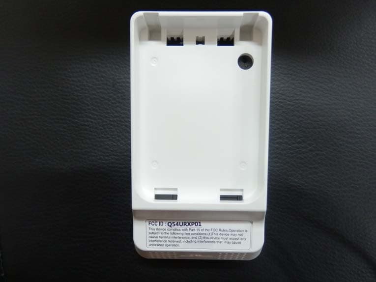
Q54URXP01
Jul 09, 2015UWB Sensor
Equipment Class
UWB - Ultra Wideband Transmitter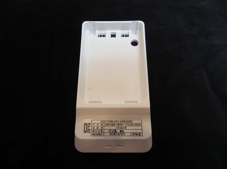
Q54URS0030X
Feb 06, 2014UWB Sensor
Equipment Class
UWB - Ultra Wideband Transmitter
Q54CDR-0130
Oct 27, 2007Smart Card Reader
Equipment Class
DXX - Part 15 Low Power Communication Device Transmitter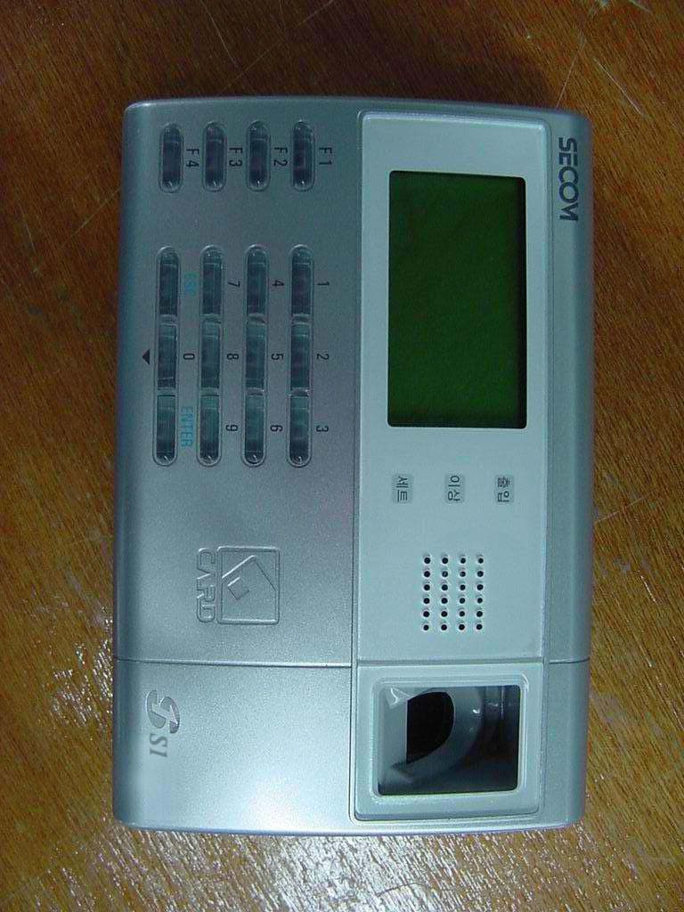
Q54CDR0193X
Oct 26, 2004RF Card & Fingerprint Terminal
Equipment Class
DXX - Part 15 Low Power Communication Device Transmitter
Q54CDR-0191
Mar 03, 2004Fingerprint Attendance & Absence Reader
Equipment Class
DXX - Part 15 Low Power Communication Device Transmitter