Q5SWU28802.11b WLAN USB Adapter
Fi Win Inc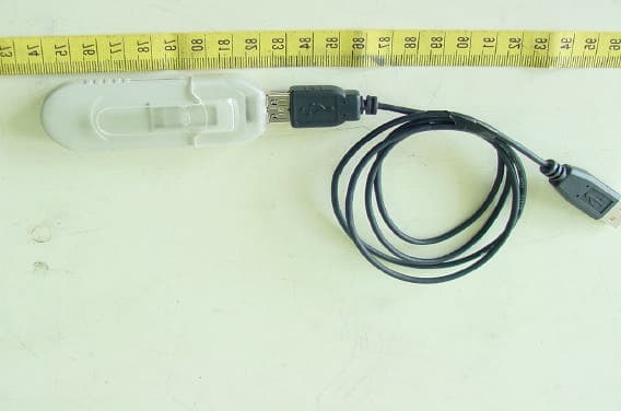
Click to zoom
Application Details
- Equipment Class
- DTS - Digital Transmission System
- Date of Grant
- May 27, 2003
- Application Purpose
- Original Equipment
- Date of Application
- May 27, 2003
- Equipment Note
- 802.11b WLAN USB Adapter
- Frequency Range
- 2412.00000000 - 2462.00000000
- Company
- Fi Win Inc
- Country
- Taiwan
Documents & Files
Document Text
Text extracted from the exhibit documents filed with the FCC. Open a document above to read the original.
Users Manual
WLAN Card User Manual Version: 0.1 2 FCC Class B Radio Frequency Interference Statement Note: This equipment has been tested and found to comply with the limits for a Class B digital device, pursuant to Part 15 of FCC Rules. These limits are designed to provide reasonable protection against harmful interference in a residential installation. This equipment generates, uses, and can radiate radio frequency energy and, if not installed and used in accordance with the instructions, may cause harmful interference to radio communications. However, there is no guarantee that interference will not occur in a particular installation. If this equipment does cause harmful interference to radio or television reception, which can be determined by turning the equipment off and on, the user is encouraged to try to correct the interference by one or more of the following measures: 1. Reorient or relocate the receiving antenna. 2. Increase the separation between the equipment and receiver. 3. Connect the equipment into an outlet on a circuit different from that to which the receiver is connected. 4. Consult the dealer or an experienced radio/television technician for help. The user should not modify or change this equipment without written approval from Fi Win, Inc. Modification could void authority to use this equipment. Notice 1: Changes or modifications not expressly approved by the party responsible for compliance could void the user's authority to operate the equipment. Notice 2: To comply with the FCC RF exposure compliance requirements, the antenna(s) used for this transmitter must not be co-located or operating in conjunction with any other antenna or transmitter . No change to the antenna or the device is permitted. Any change to the antenna or the device could result in the device exceeding the RF exposure requirements and void user’ s authority to operate the device. THIS DEVICE COMPLIES WITH PART 15 OF THE FCC RULES. OPERATIONS IS SUBJECT TO THE FOLLOWING TWO CONDITIONS: ( 1 ) THIS DEVICE MAY NOT CAUSE HARMFUL INTERFERENCE AND ( 2 ) THIS DEVICE MUST ACCEPT ANY INTERFERENCE RECEIVED, INCLUDING INTERFEERENCE THAT MAY CAUSE UNDESRIED OPERATION 3 Table of Contents 1. Introduction.......................................................................................................................3 2. Installation.........................................................................................................................3 2.1 OVERVIEW...................................................................................................................3 2.1.1 INSTALL THE WLAN UTILITY/DRIVER.............................................................4 2.1.2 INSTALL WLAN CARD ......................................................................................8 2.2 UTILITY STARTUP CONFIGURATION DETAILS........................................................9 2.2.1. Setting................................................................................................................9 2.2.2. WLAN Management Utility Introduction............................................................10 2.3 UNINSTALL THE WLAN UTILITY / DRIVER.............................................................. 25. 3. Troubleshooting ..............................................................................................29 a. Check the Various Properties of the Card..........................................................29 b. Plug the device first then install the Driver/Utility..................................................31 c. If your notebook or PC has default WLAN card, it cannot configure WiFi WLAN card..........................................................................................................31 4 1. Introduction WLAN Management Utility supports the following: 802.11b WLAN Configuration Windows 98SE / ME / 2000 (In Windows XP, we use its default WLAN Utility) PCMCIA / USB / Mini-PCI Bus Interface 2. Installation 2.1 Overview To establish your wireless network connection, the following steps should be executed. 1. Install the software using the installation CD. 2. Insert the Wireless LAN card. This product is designed for Windows 98SE, Millennium, 2000, and XP. The installation procedure for each platform is similar. Please follow the installation wizard that provided by your system install the software. 5 2.1.1 WLAN Driver/Utility Installation 1. Insert the installation CD into your CD-ROM drive. The setup program will start automatically. 6 2. Click “Next” to go to next screen. 3. Select the destination folder. To install to the default folder as shown below, click “Next” to go to the next screen. 7 4. During installation, Driver and Utility files will be copied to your system directory. 5. Select “No” and then click “Finish” to complete the installation (It is recommended to select “Yes” for Windows 98). 8 6. The shortcut will appear on your desktop. By click this icon, you can run the Utility program. You will also find a shortcut “WLAN Manager” at Start\Programs\Startup Menu as shown below: 9 7. After click the shortcut, an inverse red pyramid-like icon will appear on the bottom right of the screen. Right click that icon and select open, the WLAN Utility will pop-up on the screen. 10 2.1.2 Install the WLAN card The WLAN driver and utilities are included on the accompanying installation CD. Please follow the installation procedures in Section 2.2. (Your WLAN card will not work properly if the driver and utilities are not installed correctly). Make sure that there is an empty WLAN slot (for example PCMCIA, USB, mini-PCI) for WLAN card. Insert the WLAN Card and the installation will start automatically. When the WLAN card setup task is completed, you can run the WLAN Utility. 11 2.2 Utility Startup Configuration Details WLAN Card has its own management software. Users can control all functions provided by the application named WLAN Utility. The Utility icon will appear on the workin…
Text truncated - open the document above for the full version.
Cover Letter(s)
From: S. S. Liou [[email protected]] Sent: Wednesday, May 21, 2003 11:28 PM To: Mike Kuo Subject: Re: Fi Win Inc, FCC ID:Q5SWU28, AN03T2845 Hi Mike, Our customer do some software modification to reduce the output power to comply with the exemption of SAR evaluation. Please refer to attached test report. The authorization letter is also revised because there are two models WU28 and WU18. The difference between them is that WU18 is only 802.11 wireless LAN card but WU28 contains wireless LAN and add-in Flash Memory. They use the same schematics and layout. The user manual is revised. The RF exposure statement to declare the separation distance that end user should maintain during the operation was added. Please check. For your question 3, those frequencies you mentioned are receiving local oscillation frequencies. The levels were too low to be measured. The remarks were added on the test report. As to the test procedure in section 4.2(A), because only handheld or body worn device needs to be investigated with three axis, the procedure was corrected. Please check. regards, S. S. Liou Engineer / EMC Dep. II ETC ----- Original Message ----- From: "Mike Kuo" <[email protected]> To: "ETC/Iris (E-mail)" <[email protected]>; "Will Yauo (E-mail)" <[email protected]> Sent: Tuesday, May 13, 2003 7:05 AM Subject: FW: Fi Win Inc, FCC ID:Q5SWU28, AN03T2845 > > > -----Original Message----- > From: CERTADM > Sent: Monday, May 12, 2003 4:03 PM > To: '[email protected]' > Subject: Fi Win Inc, FCC ID:Q5SWU28, AN03T2845 > > > Notice_content > ------------- > Question #1:This device is equipped with standard USB connector. The tests > were performed with USB cable. When USB cable is used, this WLAN USB > adapter can be classified as Mobile Device where the 20cm separation > distance can be maintained by the end user. However, since this device is > equipped with standard USB connector, this device can also be used with > notebook computer. When connect to the standard notebook computer, the > separation distance will be less than 2.5cm separation from the WLAN USB > card to the body of user at lap held position. Based upon FCC guideline, > when the separation distance is less than 2.5cm, only the output power is > less than 25mW can be exempted from SAR evaluation. Otherwise, SAR > evaluation is required to qualify for TCB review. > > "Any RF exposure statement used in the user manual should not be user's > burden to maintain a minimum separation distance for satisfying compliance > with RF exposure limits. " Please address SAR evaluation issue and provide > SAR evaluation report. > > Question #2: Section 4.2(A) preliminary test procedure is misleading. This > device can be used for portable ( 2.1093) or Mobile (2.1091) application. > The test procedure described in this section indicates that device has been > tested with three axis. Per ANSI C63.4 section 13.1.4.1, only handheld or > body worn device needs to be investigated with three axis. Please provide a > test setup photo to show how the three axis were positioned. > > Question #3: Section 4.4.1 of test report, all fundamental frequencies ( > 2412, 2437, and 2462MHz ) did not report any emission field strength. > Please explain. > > Question #4: User manual does not contain RF exposure statement to declare > the separation distance that end user should maintain during the operation. > Please provide revised user manual. > > Best Regards > > Mike Kuo > The items indicated above must be submitted before processing can continue > on the above referenced application. Failure to provide the requested > information within 60 days of the original e-mail date may result in > application dismissal and forfeiture of the filing fee. Also, please note > that partial responses increase processing time and should not be submitted. > Any questions about the content of this correspondence should be directed to > the e-mail address listed below the name of the sender.
External Photos
ETC Report No. : ET92R-05-021-01 Sheet 1 of 5 Sheets FCC ID.: Q5SWU28 Rev. No 1.0 CONSTRUCTED PHOTOS of EUT 1. Total View of EUT 2. Front View of EUT ETC Report No. : ET92R-05-021-01 Sheet 2 of 5 Sheets FCC ID.: Q5SWU28 Rev. No 1.0 CONSTRUCTED PHOTOS of EUT 3. Rear View of EUT
ID Label/Location Info
LABEL REAR VIEW Label Size: 11 x 18 mm The following statement will be shown on user manual: THIS DEVICE COMPLIES WITH PART 15 OF THE FCC RULES. OPERATIONS IS SUBJECT TO THE FOLLOWING TWO CONDITIONS: ( 1 ) THIS DEVICE MAY NOT CAUSE HARMFUL INTERFERENCE AND ( 2 ) THIS DEVICE MUST ACCEPT ANY INTERFERENCE RECEIVED, INCLUDING INTERFEERENCE THAT MAY CAUSE UNDESRIED OPERATION
Internal Photos
ETC Report No. : ET92R-05-021-01 Sheet 3 of 5 Sheets FCC ID.: Q5SWU28 Rev. No 1.0 CONSTRUCTED PHOTOS of EUT 4. Internal View of EUT 5. Component View of Main PCB ETC Report No. : ET92R-05-021-01 Sheet 4 of 5 Sheets FCC ID.: Q5SWU28 Rev. No 1.0 CONSTRUCTED PHOTOS of EUT 6. Component View of Main PCB 7. Solder View of Main PCB ETC Report No. : ET92R-05-021-01 Sheet 5 of 5 Sheets FCC ID.: Q5SWU28 Rev. No 1.0 CONSTRUCTED PHOTOS of EUT 8. Component View of Main PCB 9. Solder View of Main PCB
Operational Description
The 802.11b Wireless LAN Card designed with a transmitting method of direct sequence spread spectrum is for local area network operation, which operates at 2.4 GHz ISM band and data rate up to 11 Mbps.
Test Report
Rev. No 2.0 FCC Part 15 EMI TEST REPORT of E.U.T. : 802.11b Wireless LAN Card FCC ID. : Q5SWU28 MODEL : WU28 for APPLICANT : Fi Win Inc ADDRESS : 8F, No.10, Prosperity Rd.1, Science-Based Industrial Park, Hsin Chu, Taiwan 300 Test Performed by ELECTRONICS TESTING CENTER, TAIWAN NO. 34, LIN 5, DING FU TSUN, LINKOU HSIANG TAIPEI HSIEN, TAIWAN, R.O.C. Tel : (02)26023052 Fax : (02)26010910 http://www.etc.org.tw ; e-mail: [email protected] Report Number : ET92R-05-021-01 ETC Report No. : ET92R-05-021-01 FCC ID.: Q5SWU28 Rev. No 1.0 TEST REPORT CERTIFICATION Applicant : Fi Win Inc 8F, No.10, Prosperity Rd.1, Science-Based Industrial Park, Hsin Chu, Taiwan 300 Manufacturer : Fi Win Inc 8F, No.10, Prosperity Rd.1, Science-Based Industrial Park, Hsin Chu, Taiwan 300 Description of EUT : a) Type of EUT : 802.11b Wireless LAN Card b) Trade Name : Fi Win c) Model No. : WU28 d) Power Supply : From Notebook PC e) Data also apply to : WU18 Regulation Applied : FCC Rules and Regulations Part 15 Subpart B & C (2002) I HEREBY CERTIFY THAT: The data shown in this report were made in accordance with the procedures given in ANSI C63.4, and the energy emitted by the device was founded to be within the limits applicable. I assume full responsibility for accuracy and completeness of these data. Note: 1. The result of the testing report relate only to the item tested. 2. The testing report shall not be reproduced expect in full, without the written approval of ETC. Issued Date : May 20, 2003 Test Engineer : ( Kevin Lee ) Approve & Authorized Signer : Will Yauo, Manager EMC Dept. II of ELECTRONICS TESTING CENTER, TAIWAN ETC Report No. : ET92R-05-021-01 FCC ID.: Q5SWU28 Rev. No 1.0 Table of Contents Page 1 GENERAL INFORMATION.......................................................................................................1 1.1 Product Description........................................................................................................................1 1.2 Characteristics of Device................................................................................................................1 1.3 Test Methodology..........................................................................................................................1 1.4 Test Facility....................................................................................................................................1 2 PROVISIONS APPLICABLE.......................................................................................................2 2.1 Definition........................................................................................................................................2 2.2 Requirement for Compliance...........................................................................................................3 2.3 Restricted Bands of Operation........................................................................................................5 2.4 Labeling Requirement.....................................................................................................................5 2.5 User Information............................................................................................................................6 3. SYSTEM TEST CONFIGURATION...........................................................................................7 3.1 Justification.....................................................................................................................................7 3.2 Devices for Tested System.............................................................................................................7 4 RADIATED EMISSION MEASUREMENT..............................................................................8 4.1 Applicable Standard.......................................................................................................................8 4.2 Measurement Procedure.................................................................................................................8 4.3 Measuring Instrument...................................................................................................................10 4.4 Radiated Emission Data................................................................................................................11 4.4.1 RF Portion...............................................................................................................................11 4.4.2 Other Emission........................................................................................................................16 4.5 Field Strength Calculation.............................................................................................................16 4.6 Photos of Radiation Measuring Setup............................................................................................17 5 CONDUCTED EMISSION MEASUREMENT........................................................................18 5.1 Standard Applicable.....................................................................................................................18 5.2 Measurement Procedure...............................................................................................................18 5.3 Conducted Emission Data.............................................................................................................19 5.4 Result Data Calculation.................................................................................................................20 5.5 Conducted Measurement Equipment.............................................................................................21 5.6 Photos of Conduction Measuring Setup........................................................................................22 6 ANTENNA REQUIREMENT....................................................................................................23 6.1 Standard Applicable…
Text truncated - open the document above for the full version.
Test Report
ETC Report No. : ET92R-05-021-01 Sheet 14 of 29Sheets FCC ID.: Q5SWU28 Rev. No 2.0 ETC Report No. : ET92R-05-021-01 Sheet 15 of 29Sheets FCC ID.: Q5SWU28 Rev. No 2.0 ETC Report No. : ET92R-05-021-01 Sheet 16 of 29Sheets FCC ID.: Q5SWU28 Rev. No 2.0 Appendix 4 : Ploted Datas of Band Edge Emission ETC Report No. : ET92R-05-021-01 Sheet 17 of 29Sheets FCC ID.: Q5SWU28 Rev. No 2.0 ETC Report No. : ET92R-05-021-01 Sheet 18 of 29Sheets FCC ID.: Q5SWU28 Rev. No 2.0 ETC Report No. : ET92R-05-021-01 Sheet 19 of 29Sheets FCC ID.: Q5SWU28 Rev. No 2.0 Appendix 5 : Ploted Datas of Power Density ETC Report No. : ET92R-05-021-01 Sheet 20 of 29Sheets FCC ID.: Q5SWU28 Rev. No 2.0 ETC Report No. : ET92R-05-021-01 Sheet 21 of 29Sheets FCC ID.: Q5SWU28 Rev. No 2.0 ETC Report No. : ET92R-05-021-01 Sheet 22 of 29Sheets FCC ID.: Q5SWU28 Rev. No 2.0 ETC Report No. : ET92R-05-021-01 Sheet 23 of 29Sheets FCC ID.: Q5SWU28 Rev. No 2.0 Appendix 6 : Plotted Data for Out-of-Band Conducted Emission ETC Report No. : ET92R-05-021-01 Sheet 24 of 29Sheets FCC ID.: Q5SWU28 Rev. No 2.0 ETC Report No. : ET92R-05-021-01 Sheet 25 of 29Sheets FCC ID.: Q5SWU28 Rev. No 2.0 ETC Report No. : ET92R-05-021-01 Sheet 26 of 29Sheets FCC ID.: Q5SWU28 Rev. No 2.0 ETC Report No. : ET92R-05-021-01 Sheet 27 of 29Sheets FCC ID.: Q5SWU28 Rev. No 2.0 ETC Report No. : ET92R-05-021-01 Sheet 28 of 29Sheets FCC ID.: Q5SWU28 Rev. No 2.0 ETC Report No. : ET92R-05-021-01 Sheet 29 of 29Sheets FCC ID.: Q5SWU28 Rev. No 2.0
Test Setup Photos
ETC Report No. : ET92R-05-021-01 Sheet 17 of 33Sheets FCC ID.: Q5SWU28 Rev. No 2.0 4.6 Photos of Radiation Measuring Setup ETC Report No. : ET92R-05-021-01 Sheet 22 of 33Sheets FCC ID.: Q5SWU28 Rev. No 2.0 5.6 Photos of Conduction Measuring Setup
Contact Information
Applicant
Lawrence Ching(Senior Engineer)
Test Firm
Electronics Testing Center, TaiwanWill Yauo
Technical Specifications
| # | Rule Parts | Frequency Range | Power Output |
|---|---|---|---|
| 1 | 15C | 2.41 GHz - 2.46 GHz | 21.00 mW |
Other Applications from Fi Win Inc
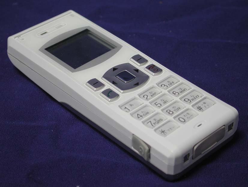
Q5S-SS28
Apr 26, 2006WiFi Phone
Equipment Class
DTS - Digital Transmission System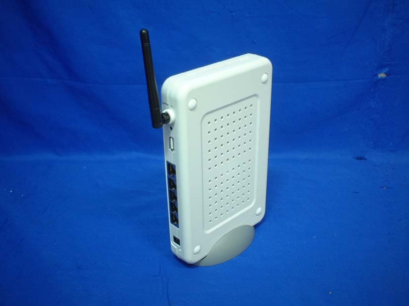
Q5S-SS38
Apr 26, 2006802.11b/g SIP-Based Wireless Gateway
Equipment Class
DTS - Digital Transmission System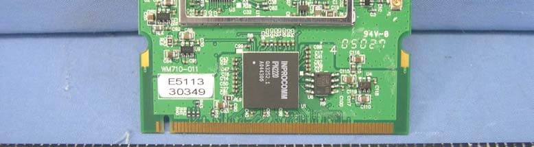
Q5SWM71
Mar 29, 200554Mbps 802.11g Wireless LAN MiniPCI Card
Equipment Class
DTS - Digital Transmission System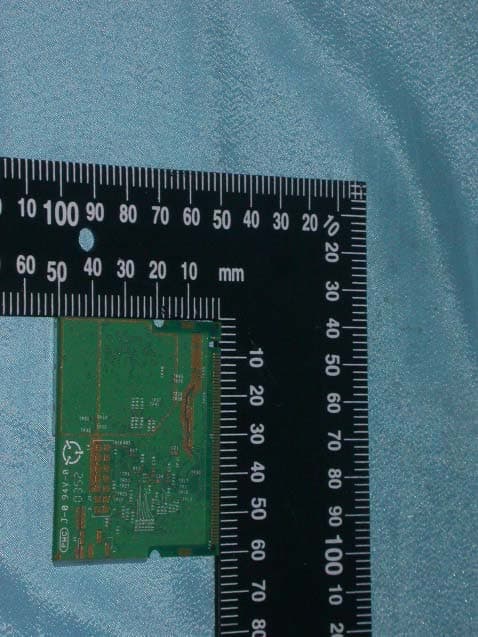
Q5SWM68-1
Jun 13, 200454Mbps 802.11g Wireless LAN MiniPCI Card
Equipment Class
DTS - Digital Transmission System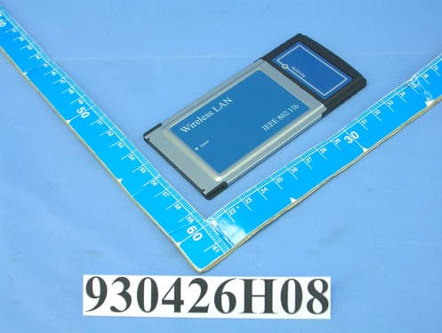
Q5SWP18
May 25, 2004802.11b Wireless PCMCIA Card
Equipment Class
DTS - Digital Transmission System