Q5TBT400G22003520BLUETOOTH HEADSET
Bluetake Technology Co., Ltd.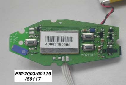
Click to zoom
Application Details
- Equipment Class
- DSS - Part 15 Spread Spectrum Transmitter
- Date of Grant
- Jun 25, 2003
- Application Purpose
- Original Equipment
- Date of Application
- Jun 25, 2003
- Equipment Note
- BLUETOOTH HEADSET
- Frequency Range
- 2402.00000000 - 2480.00000000
- Country
- Taiwan
Documents & Files
Document Text
Text extracted from the exhibit documents filed with the FCC. Open a document above to read the original.
Users Manual
BT400GII Bluetooth Headset Quick Start-Up www.bluetake.com 2 - Overview of BT400GII - DC POWER IN Earhook Speaker Microphone Open / Close the microphone The microphone can be closed when the headset doesn’t use. “Volume Up” button “Volume Down” button “Power/Talk/Pairing” button 3 1. 2. 3. - Changing the earhook - The BT400GII Bluetooth headset can be worn on either ear. Please carry out the following steps to shift the earhook for wearing it on the other ear. 1. Carefully remove the earhook from the headset 2. Change the direction of the earhook as shown in diagram 2. 3. Carefully replace the earhook on the headset. 4 - Turning the headset ON/OFF - To turn your headset ON: Press and hold the button for 3 seconds, and then the speaker will emit two high tones. When the power is on, the LED in the button starts to flash blue. (Note: The headset will go to pairing mode if you press and hold the button for 5 seconds from OFF status) To turn your headset OFF: Press and hold the button for 3 seconds, and then the speaker will emit two high tones. When the power is off, the LED in the button stops flashing. 5 - Charging the battery - Before using BT400GII you will have to charge the battery for approximate 3 hours to ensure a fully charged battery. 1. Plug the AC power adapter into the DC POWER IN socket situated at the back of the headset. 2. Plug the AC power adapter’s plug into an electrical wall outlet. 3. When charging, the LED in the button is on and re- mains lit until charging is complete. 4. Charge the headset for approximate 3 hours or until the LED in the button extinguishes. 5. Remove the AC adapter from the headset’s AC power jack. DC POWER IN Notice: The headset doesn’t work while it’s charging. 6 - Pairing to a Bluetooth phone - Please follow the instruction below to pair the headset with a Bluetooth cell phone: 1. Ensure the headset is OFF. 2. Press and hold the button for approximately 5 seconds until the headset LED starts to flash with blue and red. 3. Release the button when the LED is flashing, the status indicates that the headset is in pairing mode and waiting to pair with another Bluetooth device. 4. Follow the operating instructions for your Bluetooth phone to start a pairing process. What is Bluetooth pairing? Before using your headset for the first time, you must pair it with a particular Bluetooth cell phone previously. “Pairing” pro- cess creates a unique wireless link between two devices. Once paired, the communication between two devices do not need any authentication or authorization anymore. 7 5. Your phone’s display will indicate that it found one or more Bluetooth devices, the “Bluetake Headset” should be in- cluded in the list, please select it for pairing. 6. The phone’s display then prompt you for a pairing passkey or PIN, please enter four zeros “0000”. 7. When the pairing process is finished successfully, the headset LED will return to normal status of flashing blue only. 8. Your phone’s display may ask you whether you want to change the headset’s name, you can replace the “Bluetake Headset” with any you may prefer. 8 - Answering/Ending a call - Answering a call. After being paired with your cell phone, the headset is now ready to recevie incoming calls without handling the phone. When there’s an incoming call, both the cell phone and the headset will ring simultaneously. Upon hearing the ring tones through the headset’s speaker you can answer the incoming call by pressing button and then speaking normally. Ending a call. You can use either of the ways to end a call: 1. Press the headset’s button to end a call. 2. Press the phone’s keypad to end a call. 9 - Making a call - There are two ways to make calls: 1. Using the phone’s keypad: As general usage, dial the phone number you want to call by pressing the phone’s keypad. You may also hear the dialing tones through the headset. 2. Using the Voice Dialing through the headset: What is voice dialing? Voice dialing is a feature on some Bluetooth phones which al- lows you make calls by saying the name of the person you want to call. The phone compares your voice with your previ- ous recording (called a voice tag). If they match then the phone will automatically dial the corresponding phone number. Not all Bluetooth phones support voice dialing, please refer to your phone’s spec to make sure whether your phone supports this feature. 10 The headset does not have a keyboard so it’s necessary to use voice dialing to make calls. To do this you have to record voice tags for the contacts in your phone address book. If your phone supports voice dialing function, you can use this feature with the headset easily. Note that the voice dial- ing on your phone must be enabled and the voice tags must have been recorded previously. (Please refer to your phone’s instruction on recording and storing voice tags) a. Briefly press the button once. b. After the tone, say the name of the person you want to call. c. The phone number will be dialed automatically by phone after recognizing the correct voice tag. 11 - Appendix I - Button Function buttonTurn ON/OFFPress the button for 3 seconds until the blue LED flashes five times. Anwser/End callsPress the button once PairingWhen the headset is off, press the button to turn on and keep it pressed for about 5 seconds until the LED flashes blue and red alternately. / buttonVolume controlPress the or button repeatedly until you reach your desired level. Mute / UnmutePress the or button for about 2 seconds. 12 Audio Tone Turn OnTwo high tones Turn OffTwo low tones Pairing modeTwo high tones Incoming callA ring tone at 2 seconds interval MuteRepeated two low beeps at a 3 seconds inter- val UnmuteA single beep Battery lowStarts when the talk time is left about 3~5 minutes. At a 16 seconds interval. - Appendix II - FCC Notices This device complies with part 15 of the FCC rules. Operation is subject to the following two conditions: (1)This device may not cause harmful interference, and (2)Thi…
Text truncated - open the document above for the full version.
Block Diagram
RF Transceiver Baseband and Logic Microprocessor CODEC Matching circuit Band Pass Filter RF Antenna XTAL Speaker Microphone EEPROM LEDs and Switches 1.8 V Switching Power Supply Battery Charging circuit Bluetooth Headset Block Diagram Bluetooth Chip
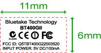
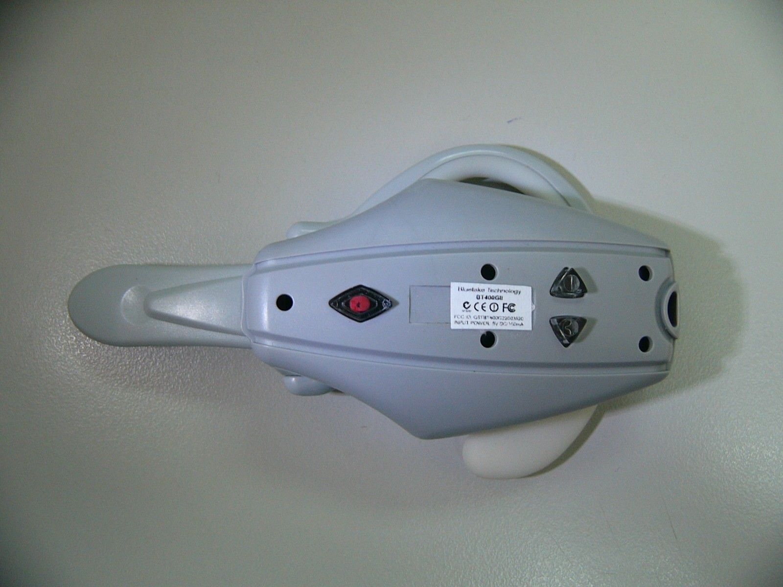
External Photos
External Photos
Internal Photos
Internal Photos
Operational Description
Operation description Bluetooth Headset 1. Purpose: The purpose of this document is to describe key component operations on Bluetooth headset. 2. Key components: CSR BlueCore2- Audio(BC213159A) Bluetooth Single Chip, ATMEL AT24C16A EEPROM, TI TPS62202DBV High-efficiency DC-DC Converter, TI BQ2057CDGK Advanced Linear Charge Management IC. 3. Operation Principle: CSR BlueCore-2 Audio (BC213159A) is a single chip radio and baseband IC for Bluetooth 2.4GHz systems. It is implemented in 0.18μm CMOS technology. When used with the CSR Bluetooth software stack, it provides a fully compliant Bluetooth system for data and voice communications. Operation at 1.7 ~ 3.6V supply. Operation clock is provided by 16MHz oscillator. Key Features Radio -Operation with common TX/RX terminals simplifies external matching circuitry and eliminates external antenna switch -Extensive built-in self-test minimizes production test time -No external trimming is required in production -Full RF reference designs are available Transmitter -Up to +6dBm RF transmit power with level control from the on-chip 6-bit DAC over a dynamic range greater than 30dB -Supports Class 2 and Class 3 radios without the need for an external power amplifier or TX/RX switch -Support Class 1 radio with an external power amplifier, provided by a power control terminal controlled by an internal 8-bit voltage DAC and an external RF TX/RX switch Receiver -Integrated channel filters -Digital demodulator for improved sensitivity and co-channel rejection -Digitized RSSI available in real time over the HCI interface -Fast AGC for enhanced dynamic range Synthesizer -Fully integrated synthesizer, no external VCO varactor diode, resonator or loop filter -Compatible with crystals between 8 and 32MHz (in multiples of 250KHz) or an external clock -Accepts 15.36, 16.2, 19.2, 19.44, 19.68, 19.8 and 38.4MHz TCXO frequencies for GSM and CDMA devices with either sinusoidal or logic level signals Auxiliary Features -Crystal oscillator with built-in digital trimming -Power management includes digital shut down and wake up commands and an integrated low power oscillator for ultra-low Park/Sniff/Hold mode power consumption -Devices can be used with an external master oscillator and provides a ‘clock request signal’ to control external clock source. -On-chip linear regulator, producing 1.80V output from 2.2-3.6V input -Power-on-reset cell detects low supply voltage -Arbitrary sequencing of power supplies is permitted -Uncommitted 8-bit ADC and 8-bit DAC are available to application programs Baseband and software -Internal programmed 4Mbit ROM for complete system solution -32Kbyte on-chip RAM allows full speed Bluetooth data transfer, mixed voice and data, plus full 7 slaves piconet operation -Dedicated logic for forward error correction, header error control, access code correlation, demodulation, cyclic redundancy check, encryption bit-stream generation, whitening and transmit pulse shaping -Transponders for A-law, μ-law and linear voice from host and A-law, μ-law and CVSD voice over air Physical Interfaces -Synchronous serial interface up to 4Mbaud for system debugging -UART interface with programmable Baud rate up to 1.5Mbaud with an optional bypass mode -Full speed USB interface supports OHCI and UHCI host interfaces. Compliant with USB v2.0 -Synchronous bi-directional serial programmable audio interface -Operational I 2 C TM Compatible interface Bluetooth Stack Running on an Internal Microcontroller CSR’s Bluetooth Protocol Stack runs on-chip in a variety of configurations: -Standard HCI (UART or USB) -Fully embedded to RFCOMM -Customer specific builds with embedded application code ATMEL AT24C16A EEPROM The AT24C16A provides 16384 bits of serial electrically erasable and programmable read only memory (EEROM) organized as 2048 words of 8 bits each. The device is optimized for use in many industrial and commercial applications where low power and low voltage operation are essential. Features: z Write Protect Pin for Hardware Data Protection z Low-voltage and Standard-voltage Operation - 2.7 (V CC = 2.7V to 5.5V) - 1.8 (V CC = 1.8V to 5.5V) z 2-wire Serial Interface z Schmitt Trigger, Filtered Inputs for Noise Suppression z Bi-directional Data Transfer Protocol z 100 kHz(1.8V) and 400 kHz(2.5V, 2.7V and 5V) Clock Rate z 16-byte Page Write Modes z Partial Page Writes are Allowed z Self-timed Write Cycle (10 ms max) z High Reliability - Endurance: One Million Write Cycles - Data Retention: 100 years z Automotive Grade and Extended Temperature Devices Available z 8-lead PDIP, 8-lead JEDEC SOIC, 8-lead MAP and 8-lead TSSOP Packages TI TPS62202DBV High-efficiency DC-DC Converter The TPS6220x devices are a family of high-efficiency synchronous step-down converters ideally suited for portable systems powered by 1-cell Li-Ion or 3-cell NiMH/NiCd batteries. The devices are also suitable to operate from a standard 3.3-V or 5-V voltage rail. With an output voltage range of 6.0V down to 0.7V and up to 30 mA output current, the devices are ideal to power low voltage DSPs and processors used in PDAs, pocket PCs, and smart phones. Under nominal load current, the devices operate with a fixed switching frequency of typically 1 MHz. At light load currents, the part enters the power save mode operation; the switching frequency is reduced and quiescent current is typically only 15 uA; therefore it achieves the highest efficiency over the entire load current range. Features: z High Efficiency Synchronous Step-Down Converter With up to 95% Efficiency z 2.5 V to 6.0 V Input Voltage Range z Adjustable Output Voltage Range From .7 V to V I z Fixed Output Voltage Options Available z Up to 300 mA Output Current z 1 MHz Fixed Frequency PWM Operation z Highest Efficiency Over Wide Load Current Range Due to Power Save Mode z 15-uA Typical Quiescent Current z Soft Start z 100% Duty Cycle Low-Dropout Operation z Dynamic Output Voltage Positioning z Available in a Tiny 5-Pin SOT23 Package TI BQ20…
Text truncated - open the document above for the full version.
Schematics
55 44 33 22 11 D D C C B B A A R1: Icharge:1R0 100mA1R2 88mA1R5 70mA1R8 58mA2R0 50mA2R2 46mA Q3 123654 Q2 3 2 1 5 64 Q2 3 2 1 5 64 Q3 3 2 1 5 64 Q1 E B C D1 2 1 3 WV-6.3V YBMH-12J-R7.DSN 0 YasingTech Bluetooth Class2 headset(YBMH-12J-R7) A3 11 Wednesday, March 12, 2003 TitleSize Document Number Rev Date: Sheet of XTALO XTALI PIO3 PIO4 PIO5 TX_B TX_NETA TX_A TX_NETB ANT_POINT PIO11 BAT_MON PIO2 VOUT PIO9 PIO9 POWER_IN PIO0 1V8_EN PIO0 PIO1 ANT POWER_IN 1V8 1V8 1V8 1V8 1V8 1V8 VBAT VBAT VBAT VBAT 1V8 1V8 1V8 VBAT C1647n U2TPS62202DBV 54 1 2 3 LX OUT/FB IN GND nSHDN S1TALK 1 2 L43n9 T3 R1047K R7470R R17100K R5NF(150K) T9 R4150K R112R2 J2BATTERY CON 12 U6HHM-1517 1 2 34 5 6 T17 MIC_P T4 C132p2 U4AT24C16A 84123 567 VCC GND A0A1A2 SDASCLWP T11 C142p2 T10 J3EAR CONNECTOR 12 S2VOL+ 1 2 T2 D1BAT54W 1 2 3 R11R5(1%)(0805) C310u T12 T1 C182u2 T18 MIC_N C2110u(Tantalum) R847K C1915p C1115p U1BQ2057CDGK 12 3 4 5 6 78 VCCTS STAT VSS CC COMP SNS BAT C1747n R222K2 J4MIC CONNECTOR 12 R2150KS3VOL- 1 2 C1510n R1947K AN1ANT 1 2 ANT NC R142K2 L53n9 C63p3 C1233p U5MDR741F 12 34 INGNDGND OUT Q3BBC847BS 34 5 TP1 C910n T8 Q1BC856BW B EC J1+6V_INPUT 132 L7NF(3n9) X116MHz 1 3 2 4 T15 EAR_P L215n R31K U3BC215159A H4 C3 C1 C2 H1 E10 J6 A7 A9 H6 A6 K7 D10 A3 K4 K9 D8 B8 K6 K3 K2 J3 B3 B4 E8 F8 B1 B2 F10F9C5H9J10H7H8C10C8B9C9J8K8C7C6H5J5 G10 G9 G8 H10 C4 B6 K5 A5 A8 A4 E3 G3 H3 K1 J1 F3 D9 B5 B7 A10 J7 B10 E9 A2 A1 K10 J9 E2 F2 D2 J4 J2 G1 G2 H2 E1 F1 D1D3 AIO[0] PIO[9] VDD_RADIO VDD_RADIO VDD_VCO VDD_CORE VDD_MEM VDD_MEM VDD_MEM VDD_MEM VDD_MEM VDD_MEM VDD_PADS VDD_PIO VDD_ANA VDD_USB RESETB FLASH_EN VREG_IN XTAL_IN VSS_ANA XTAL_OUT PIO[2] PIO[3] PIO[4] PIO[5] PIO[0] PIO[1] PIO[6]PIO[7]PIO[8] UART_RX UART_TX UART_RTSUART_CTS SPI_CLK SPI_MOSISPI_MISO SPI_CSB USB_DP USB_DN RESET TEST_EN AIO[1]AIO[2] PCM_SYNC PCM_IN PCM_OUT PCM_CLK PIO[10] N/C N/C N/C N/C N/C PIO[11] MIC_N MIC_P SPKR_N SPKR_P VSS VSS_PADS VSS_MEM VSS_MEM VSS_MEM VSS_MEM VSS_MEM VSS_CORE VSS_PIO VSS_PIO VSS_USB VSS_USB VSS_RADIO VSS_RADIO VSS_RADIO VSS_ANA VSS_ANA VSS_VCO VSS_VCO LOOP_FILTER TX_BTX_ARF_INAUX_DAC Q3ABC847BS 61 2 T7 R132K2 D2RED LED AK L110u R181K5 R16150K(1%) C2100n C85p6 T13 D3BLUE LED AK R6150K C4100n C710p Q2ABC847BS 61 2 T6 R12220K(1%) C110u R9470R L615n T16 EAR_N C510n R152K2 L315n Q2BBC847BS 34 5 T14 T5 C1010n PIO9 PIO2 PIO9 PIO0 PIO0 POWER_IN POWER_IN
Test Report
Report No. : ER/2003/50014 Page : 1 of 46 TEST REPORT Product Name : Bluetooth Headset Product ID : BT400GII Applicant : Bluetake Technology Co., Ltd. Address of Applicant : 6F, No. 33, Lane 155, Sec. 3, Pei Shen Road, Shen Keng Shiang, Taipei, Taiwan , R.O.C. Standards: FCC Part 15 subpart C In the configuration tested, the EUT complied with the standards specified above. The test data, test procedures, and equipment configurations shown in this report were made in accordance with the procedures given in ANSI C63.4(1992). Remarks: This report details the results of the testing carried out on one sample, the results contained in this test report do not relate to other samples of the same product. The manufacturer should ensure that all products in series production are in conformity with the product sample detailed in this report. This report may only be reproduced and distributed in full. If the product in this report is used in any configuration other than that detailed in the report, the manufacturer must ensure the new system complies with all relevant standards. Any mention of SGS Taiwan E&E Services or testing done by SGS Taiwan E&E Services in connection with distribution or use of the product described in this report must be approved by SGS Taiwan E&E Services in writing. Tested by : Alex Hsieh Date : Jun. 5, 2003 Approved by : Robert Chang Date : Jun. 10, 2003 Report No. : ER/2003/50014 Page : 2 of 46 Contents 1. General Information 1.1 Testing Laboratory 3 1.2 Details of Applicant 3 1.3 Description of EUT(s) 3 1.4 Operation Procedure 4 2. Summary of Results 5 3. Instruments List 6 4. Measurements 7 4.1 Conducted Limits 7 4.2 Radiated emission Limits, general requirement 10 4.3 Channel Spacing 17 4.4 20db bandwidth / No. of channels 19 4.5 Average time of Occupacy 24 4.6 Peak outpot power 27 4.7 Band-edge emission 30 4.8 Spurious Emission under 25Ghz 32 APPENDIX Photographs of Test Setup 44 Photographs of EUT 45-46 Report No. : ER/2003/50014 Page : 3 of 46 1. General Information 1.1 Testing Laboratory SGS Taiwan Ltd. ( FCC Registration number: 573967 ) 1F, No. 134, Wukung Road, Wuku industrial zone Taipei county , Taiwan , R.O.C. Telephone : +886-2-2299-3279 Fax : +886-2-2298-2698 Internet : http://www.sgs.com.tw 1.2 Details of Applicant Name : Bluetake Technology Co., Ltd. Address : 6F, No. 33, Lane 155, Sec. 3, Pei Shen Road, Shen Keng Shiang, Taipei, Taiwan , R.O.C. Contact : Ming Chen Telephone : +886-2-2664-7199 1.3 Description of EUT(s) 1 Product name Bluetooth Headset 2 Product ID BT400GII 3 Supply Voltage DC 3.3V 4 Carrier Frequency 2402MHz to 2480MHz 5 Modulation Method GFSK,1Mbps,0.5BT Gaussian 6 Hopping 1600hops/sec, 1MHz channel space 7 Operation Temperature 0 to +60 degree 8 Compliant Bluetooth Specification Ver1.1 Report No. : ER/2003/50014 Page : 4 of 46 1.4 Operation Procedure Since Bluetooth is a FHSS system, it is difficult to measure the parameters under hopping mode. The output power and operating frequency are NOT End-user adjustable. Applicant offer a engineering software “BlueTest” install in PC to control the EUT. And the applicant provide an additional UART interface (RS232) to control this Headset. Operating frequency are set as testing required. The output power is set as Ext=255, Int=55. The lowest operating frequency within Bluetooth specification is 2402Mhz, and highest operating frequency is 2480Mhz. So the frequency above are used as the lowest and highest frequency in the testing, and the middle frequency is set as 2441Mhz. The pseudorandom hopping sequence is produced by the Bluesuite software which is provided by the manufacturer of the chipset. 1.5 Testing Method The testing standard follows CFR 47, Part 15.247 , and measurement method according to Public Notice DA00-705 (March 2000). Report No. : ER/2003/50014 Page : 5 of 46 2.Summary of Results subclause Parameter to be measures Verdict Page 15.207 Conducted Limits PASS 7 15.209 Radiated emission Limits, general requirement PASS 10 15.247(a)(1) Channel Spacing PASS 17 15.247(a)(1)(ii) 20db bandwidth / No. of channels PASS 19 15.247(a)(1)(ii) Average Time of Occupancy PASS 24 15.247(b)(1) Peak Output power PASS 27 15.247(c) Band-Edge Emission PASS 30 15.247(c) Spurious Emission under 25Ghz PASS 32 Report No. : ER/2003/50014 Page : 6 of 46 3. Instruments List Instrument Model Serial number Calibration date Desktop PC HP Pavillion 723DN/A N/A Spectrum Analyzer Agilent 7405A US40240202 Jun 01, 2002 Spectrum Analyzer R&S FSP 40 100034 Mar. 27, 2003 Antenna Schwarzbeck BBHA9170A 184/185 July 01, 2002 Antenna Schwarzbeck BBHA9120A 309/320 July 01, 2002 Antenna Schwarzbeck VULB9163 152 July 01, 2002 Signal generator R&S SMR 40 100210 Feb. 11, 2003 EMC Analyzer HP 8594EM 3624A00203 Dec. 13, 2002 EMI Test Receiver R&S ESCS 30 828985/004 Oct. 11, 2002 Transient Limiter HP 11947A 3107A02062 Jul. 24, 2002 L.I.S.N Rolf-Heine NNB-2/16Z 99012 Oct. 08, 2002 Report No. : ER/2003/50014 Page : 7 of 46 4. Measurements 4.1 Conducted Limits SUBCLAUSE 15.207 Line Report No. : ER/2003/50014 Page : 8 of 46 Neural Report No. : ER/2003/50014 Page : 9 of 46 4.1.1 Limits (EN55022) Limits dB(uV) Frequency range Mhz Quasi-peak Average 0.15 to 0.5 66 to 56 56 to 46 0.5 to 5 56 46 5 to 30 60 50 Report No. : ER/2003/50014 Page : 10 of 46 4.2 Radiated emission Limits, general requirement SUBCLAUSE 15.209 Part 1: 30Mhz-1000Mhz , transmit at 2402Mhz Vertical Report No. : ER/2003/50014 Page : 11 of 46 Horizontal Report No. : ER/2003/50014 Page : 12 of 46 Part 2: 30Mhz-1000Mhz , transmit at 2441Mhz Vertical Report No. : ER/2003/50014 Page : 13 of 46 Horizontal Report No. : ER/2003/50014 Page : 14 of 46 Part 3: 30Mhz-1000Mhz , transmit at 2480Mhz Vertical Report No. : ER/2003/50014 Page : 15 of 46 Horizontal Report No. : ER/2003/50014 Page : 16 of 46 4.2.1 Limits Report No. : ER/2003/50014 Page : 17 of 46 4.3 Channel Separation SUBCLAUSE15.247(a)(1) Report No. : ER/2003/50014 Page : 18 of 46 Lowest channel Highest channel Channel s…
Text truncated - open the document above for the full version.
Test Setup Photos
Test Setup Photos
Contact Information
Applicant
Gavin Chan(Marketing Manager)
Test Firm
SGS Taiwan Ltd.Jason Lin
Technical Specifications
| # | Rule Parts | Frequency Range | Power Output |
|---|---|---|---|
| 1 | 15C | 2.40 GHz - 2.48 GHz | 1.30 mW |
Other Applications from Bluetake Technology Co., Ltd.
Q5TBT220
Mar 28, 2007Bluetooth Printer Adapter
Equipment Class
DSS - Part 15 Spread Spectrum Transmitter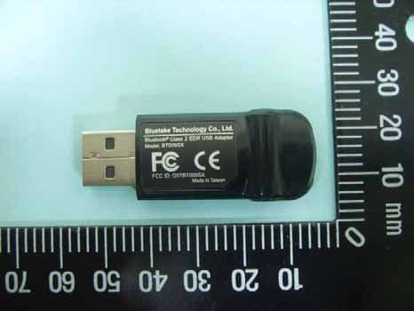
Q5TBT009SX
Nov 01, 2006Bluetooth Class 2 EDR USB Adapter
Equipment Class
DSS - Part 15 Spread Spectrum Transmitter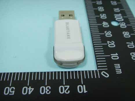
Q5TBT007SX
Oct 29, 2006Bluetooth Class 1 EDR USB Adapter
Equipment Class
DSS - Part 15 Spread Spectrum Transmitter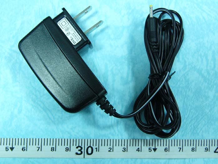
Q5TBT420RX0511A
Jan 26, 2006Bluetooth Stereo Headphone
Equipment Class
DSS - Part 15 Spread Spectrum Transmitter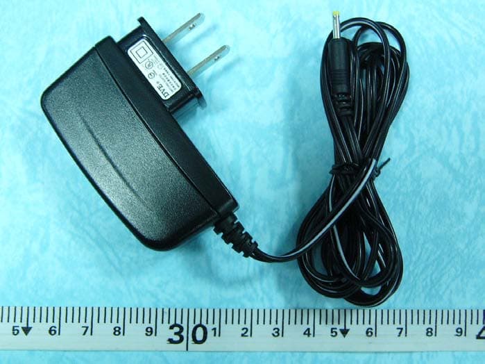
Q5TBT430TX0511A
Jan 26, 2006Bluetooth Stereo Headphone
Equipment Class
DSS - Part 15 Spread Spectrum Transmitter