Q6G-MF16S32E9WFirebox X Edge
WatchGuard Technologies, Inc.
Click to zoom
Application Details
- Equipment Class
- DTS - Digital Transmission System
- Date of Grant
- Oct 11, 2004
- Application Purpose
- Original Equipment
- Date of Application
- Oct 11, 2004
- Equipment Note
- Firebox X Edge
- Frequency Range
- 2400.00000000 - 2483.50000000
- Country
- United States
Documents & Files
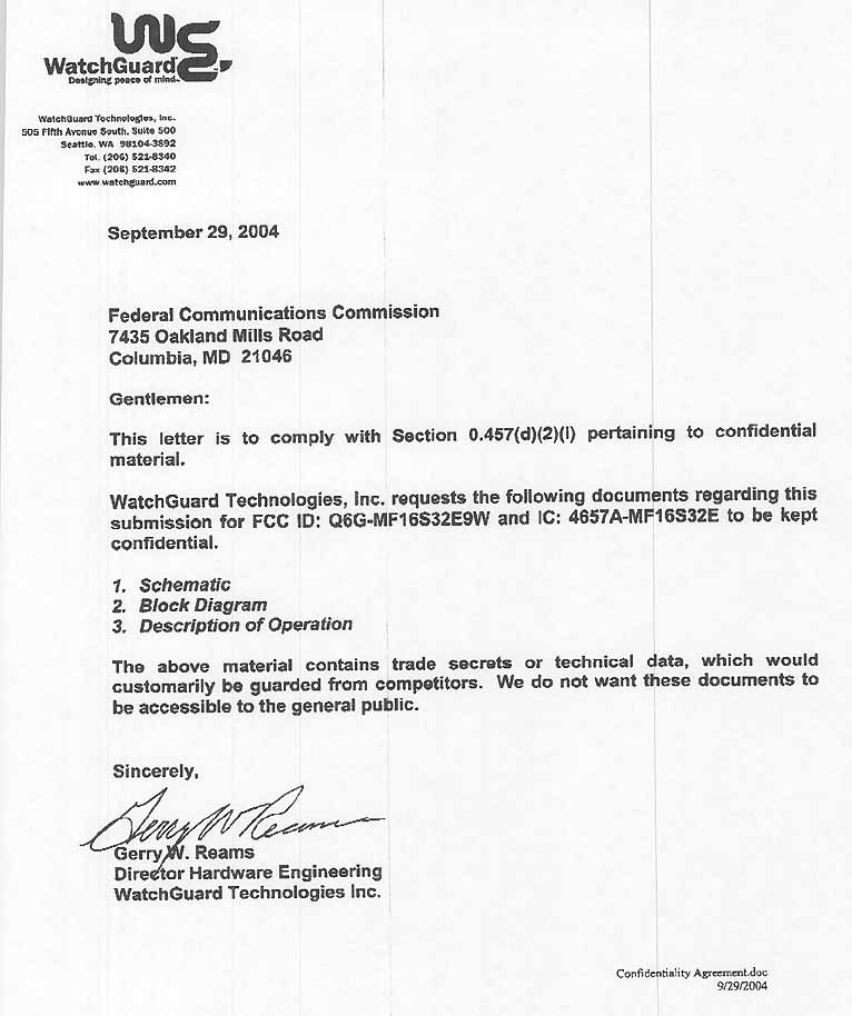
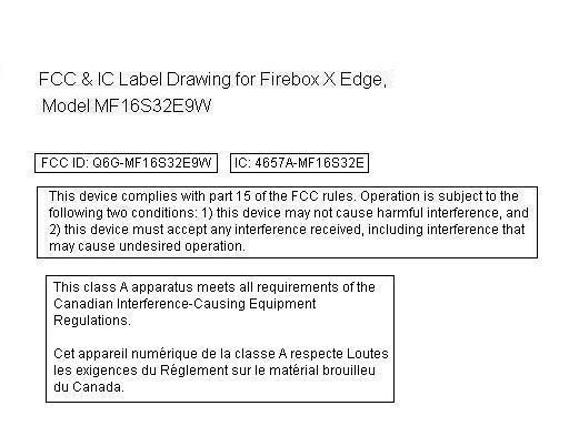
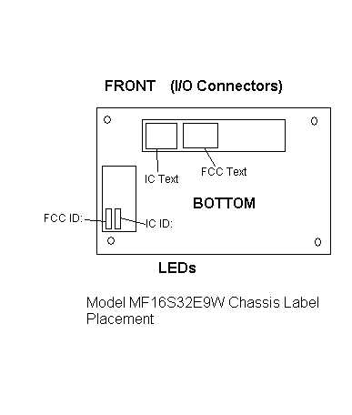
Document Text
Text extracted from the exhibit documents filed with the FCC. Open a document above to read the original.
Users Manual
WatchGuard ® Firebox ® X Edge User Guide Firebox X Edge - Firmware Version 7.1 iiWatchGuard Firebox X Edge Certifications and Notices FCC Certification This appliance has been tested and found to comply with limits for a Class A digital appliance, pursuant to Part 15 of the FCC Rules. Operation is subject to the following two conditions: - This appliance may not cause harmful interference. - This appliance must accept any interference received, including interference that may cause undesired operation. Changes or modifications not expressly approved by the party responsible for compliance could void the user's authority to operate the equipment. This equipment has been tested and found to comply with the limits for a Class A digital device, pursuant to Part 15 of the FCC Rules. These limits are designed to provide reasonable protection against harmful interference when the equipment is operated in a commercial environment. This equipment generates, uses, and can radiate radio frequency energy and, if not installed and used in accordance with the instruction manual, may cause harmful interference to radio communications. Operation of this equipment in a residential area is likely to cause harmful interference in which case the user will be required to correct the interference at his own expense. CE Notice The CE symbol on your WatchGuard Technologies equipment indicates that it is in compliance with the Electromagnetic Compatibility (EMC) directive and the Low Voltage Directive (LVD) of the European Union (EU). Industry Canada This Class A digital apparatus meets all requirements of the Canadian Interference-Causing Equipment Regulations. Cet appareil numerique de la classe A respecte toutes les exigences du Reglement sur le materiel broulleur du Canada. Certifications and Notices User Guideiii CANADA RSS-210 The term “IC:” before the radio certification number only signifies that Industry of Canada technical specifications were met. Operation is subject to the following two conditions: (1) this device may not cause interference, and (2) this device must accept any interference, including interference that may cause undesired operation of the device. VCCI Notice Class A ITE ivWatchGuard Firebox X Edge Declaration of Conformity Notice to Users User Guidev Notice to Users Information in this guide is subject to change without notice. Companies, names, and data used in examples herein are fictitious unless otherwise noted. No part of this guide may be reproduced or transmitted in any form or by any means, electronic or mechanical, for any purpose, without the express written permission of WatchGuard Technologies, Inc. WatchGuard Firebox Software End-User License Agreement IMPORTANT - READ CAREFULLY BEFORE ACCESSING WATCHGUARD SOFTWARE: This Firebox Software End-User License Agreement (“AGREEMENT”) is a legal agreement between you (either an individual or a single entity) and WatchGuard Technologies, Inc. (“WATCHGUARD”) for the WATCHGUARD Firebox software product, which includes computer software components (whether installed separately on a computer workstation or on the WATCHGUARD hardware product or included on the WATCHGUARD hardware product) and may include associated media, printed materials, and on-line or electronic documentation, and any updates or modifications thereto, including those received through the WatchGuard LiveSecurity Service (or its equivalent), (the “SOFTWARE PRODUCT”). WATCHGUARD is willing to license the SOFTWARE PRODUCT to you only on the condition that you accept all of the terms contained in this Agreement. Please read this Agreement carefully. By installing or using the SOFTWARE PRODUCT you agree to be bound by the terms of this Agreement. If you do not agree to the terms of this AGREEMENT, WATCHGUARD will not license the SOFTWARE PRODUCT to you, and you will not have any rights in the SOFTWARE PRODUCT. In that case, promptly return the SOFTWARE PRODUCT, along with proof of payment, to the authorized dealer from whom you obtained the SOFTWARE PRODUCT for a full refund of the price you paid. The WATCHGUARD hardware product is subject to a separate agreement and limited hardware warranty included with the WATCHGUARD hardware product packaging and/or in the associated user documentation. 1. Ownership and License. The SOFTWARE PRODUCT is protected by copyright laws and international copyright treaties, as well as other intellectual property laws and treaties. This is a license agreement and NOT an agreement for sale. All title and copyrights in and to the SOFTWARE PRODUCT (including but not limited to any images, photographs, animations, video, audio, music, text, and applets incorporated into the SOFTWARE PRODUCT), the accompanying printed materials, and any copies of the SOFTWARE PRODUCT are owned by WATCHGUARD or its licensors. Your rights to use the SOFTWARE PRODUCT are as specified in this AGREEMENT, and WATCHGUARD retains all rights not expressly granted to you in this AGREEMENT. Nothing in this AGREEMENT constitutes a waiver of our rights under U.S. copyright law or any other law or treaty. 2. Permitted Uses. You are granted the following rights to the SOFTWARE PRODUCT: (A)You may install and use the SOFTWARE PRODUCT on any single WATCHGUARD hardware product at any single location and may install and use the SOFTWARE PRODUCT on multiple workstation computers. (B)To use the SOFTWARE PRODUCT on more than one WATCHGUARD hardware product at once, you must purchase an additional copy of the SOFTWARE PRODUCT for each additional WATCHGUARD hardware product on which you want to use it. To the extent that you install copies of the SOFTWARE PRODUCT on additional WATCHGUARD hardware products in accordance with the prior sentence without installing the additional copies of the SOFTWARE PRODUCT included with such WATCHGUARD hardware products, you agree that use of any software provided with or included on the additional WATCHGUARD hardware products that does not require in…
Text truncated - open the document above for the full version.
Cover Letter(s)
Response to E04-000087-1 1. The label location has been uploaded in the proper format. 2. Testing was performed below 30 MHz, but no emissions were found.
Cover Letter(s)
Response to E04-000087-2 1. A revised test report has been uploaded with a revised data sheet for sequence 13. This data sheet incorporated 15.209 limits for frequencies which were not inside a restricted band. The readings were recalculated to 15.247(c) (-20dBc) limits. As reported, there are no readings >20dB over the average limit. Response to E04-000087-2 IC 1. A revised Appendix II has been uploaded.
Cover Letter(s)
Additional Note on FCC Submittal for MF16S32E9W Referring to the contents of the MF16S32E9W.Zip file: The MB901A Mini-PCI card Schematic and Block Diagram were provided by Sercomm, the manufacturer of the MF16S32E9W product. The MF16S32E9W Description of Operation was written by me based on Atheros Datasheets for the AR5213A and AR5112A chip set. After reviewing these documents I noted a couple of items. 1) There is a crystal Y1 shown on the schematic (page 2 of 5), however, the schematic revision comments (page 1 of 5)say that Y1 has been removed. I checked the Mini-PCI card and the crystal has been removed. 2) The schematic shows an AR5112 Radio Chip, however there is an AR5112A part on the Mini-PCI card, and that part is what we have tested and plan to ship. George Stults Compliance Engineer WatchGuard Technologies Inc.
External Photos
Overall Front Back Top Bottom Left Right
Internal Photos
Internal Overall Main PCB Top Main PCB Bottom Transmitter PCB Top Transmitter PCB Top without Shield Transmitter PCB Bottom
Test Report
Page 1 of 92 Report No: FC04-065A ADDENDUM TO WATCHGUARD TECHNOLOGIES INC. TEST REPORT FC04-065 FOR THE FIREBOX X EDGE, MF16S32E9W FCC PART 15 SUBPART C SECTIONS 15.207, 15.209 AND15.247 AND RSS-210 COMPLIANCE DATE OF ISSUE: OCTOBER 8, 2004 PREPARED FOR: Watchguard Technologies Inc. 505 Fifth avenue South, Suite 500 Seattle, WA 98104-3892 PREPARED BY: Mary Ellen Clayton CKC Laboratories, Inc. 5473A Clouds Rest Mariposa, CA 95338 P.O. No.: W.O. No.: 241145 82546 Date of test: August 17-25, 2004 Report No.: FC04-065A This report contains a total of 92 pages and may be reproduced in full only. Partial reproduction may only be done with the written consent of CKC Laboratories, Inc. The results in this report apply only to the items tested, as identified herein. Page 2 of 92 Report No: FC04-065A TABLE OF CONTENTS Administrative Information .............................................................................................4 Summary of Results .........................................................................................................5 Conditions for Compliance ..............................................................................................5 Approvals .........................................................................................................................5 Equipment Under Test (EUT) Description ......................................................................6 FCC 15.31(e) Voltage Variation......................................................................................6 FCC 15.31(m) Number Of Channels ...............................................................................6 FCC 15.33(a) Frequency Ranges Tested .........................................................................6 FCC 15.35 Analyzer Bandwidth Settings ........................................................................6 FCC 15.203 Antenna Requirements ................................................................................6 FCC 15.205 Restricted Bands..........................................................................................6 Eut Operating Frequency .................................................................................................7 Equipment Under Test .....................................................................................................7 Peripheral Devices ...........................................................................................................7 Report of Measurements ..................................................................................................8 Table 1: FCC 15.207 Six Highest Conducted Emission Levels .....................................8 Table 2: FCC 15.209/15.247 Six Highest Radiated Emission Levels: 30 MHz – 25 GHz...... 9 Table 3: FCC 15.209/15.247 Six Highest Radiated Emission Levels: 2.4-25 GHz .......10 FCC 15.247(a)(2) 6dB Bandwidth..................................................................................11 FCC 15.247(b)(3) Peak Power Output Antenna Conducted...........................................16 Table 4: FCC 15.247(c) Six Highest Radiated Emission Levels - Antenna Conducted .16 FCC 15.247(c)(2) 6dB Bandwidth..................................................................................16 FCC 15.247(c) Bandedge................................................................................................16 FCC 15.247 (d) Power Spectral Density.........................................................................16 RSS-210 Bandedge .........................................................................................................16 RSS-210 99% 20 dBc Bandwidth...................................................................................16 Temperature And Humidity During Testing....................................................................16 EUT Setup........................................................................................................................16 Correction Factors............................................................................................................16 Table A: Sample Calculations .............................................................................16 Test Instrumentation and Analyzer Settings ....................................................................16 Spectrum Analyzer Detector Functions ...............................................................16 Peak..........................................................................................................16 Quasi-Peak ...............................................................................................16 Average ....................................................................................................16 EUT Testing.....................................................................................................................16 Mains Conducted Emissions................................................................................16 Antenna Conducted Emissions ............................................................................16 Radiated Emissions ..............................................................................................16 Appendix A: Information about the Equipment Under Test ...........................................16 I/O Ports ...............................................................................................................16 Crystal Oscillators................................................................................................16 Printed Circuit Boards..........................................................................................16 Page 3 of 92 Report No: FC04-065A Cable Information ................................................................................................16 Equipment Test Setup Diagram ...........................................................................16 Photograph Show…
Text truncated - open the document above for the full version.
Test Setup Photos
PHOTOGRAPH SHOWING MAINS CONDUCTED EMISSIONS Mains Conducted Emissions - Front View PHOTOGRAPH SHOWING MAINS CONDUCTED EMISSIONS Mains Conducted Emissions - Side View PHOTOGRAPH SHOWING RADIATED EMISSIONS Radiated Emissions - Front View PHOTOGRAPH SHOWING RADIATED EMISSIONS Radiated Emissions - Back View PHOTOGRAPH SHOWING DIRECT CONNECT TEST SETUP
Contact Information
Applicant
Jay Lindenauer(Vice President of Product Delivery Operations)
Technical Contact
CKC Laboratories, Inc.MaryEllen Clayton
[email protected]209-966-5240
5473A Clouds Rest · Mariposa, California · United States
Non-Technical Contact
CKC Laboratories, Inc.MaryEllen Clayton
[email protected]209-966-5240
Test Firm
CKC Laboratories, Inc.Steve Behm
Technical Specifications
| # | Rule Parts | Frequency Range | Power Output |
|---|---|---|---|
| 1 | 15C | 2.40 GHz - 2.48 GHz | 57.00 mW |
Other Applications from WatchGuard Technologies, Inc.
Q6G-AP230W
Mar 12, 2024Wireless Access Point
Equipment Class
NII - Unlicensed National Information Infrastructure TX
Q6G-AP430CR
Jul 08, 2021Wireless Access Point
Equipment Class
DTS - Digital Transmission System
Q6G-AP330
Apr 11, 2021Wireless Access Point
Equipment Class
DTS - Digital Transmission System
Q6G-AP130
Jan 19, 2021Wireless Access Point
Equipment Class
NII - Unlicensed National Information Infrastructure TX
Q6G-FS4AE5W
May 19, 2020Firebox T40-W
Equipment Class
NII - Unlicensed National Information Infrastructure TX