Q6G-XP2E6WInternet Firewall
WatchGuard Technologies, Inc.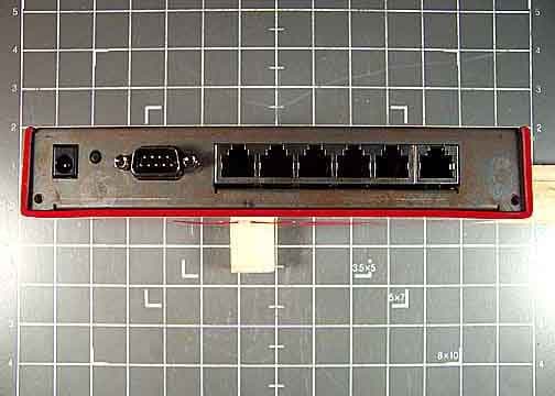
Click to zoom
Application Details
- Equipment Class
- DTS - Digital Transmission System
- Date of Grant
- Jan 05, 2006
- Application Purpose
- Original Equipment
- Date of Application
- Jan 05, 2006
- Equipment Note
- Internet Firewall
- Frequency Range
- 2412.00000000 - 2462.00000000
- Country
- United States
Documents & Files
Document Text
Text extracted from the exhibit documents filed with the FCC. Open a document above to read the original.
Users Manual
User Guide219 APPENDIX AFirebox X Edge e-Series Hardware The WatchGuard® Firebox® X Edge e-Series is a firewall for small organizations and branch offices. The Firebox X Edge e-Series product line includes: •Firebox X Edge e-Series •Firebox X Edge e-Series Wireless •Firebox X Edge e-Series DSL Package Contents The Firebox® X Edge e-Series package includes: •Hardware firewall 220 WatchGuard Firebox X Edge •Firebox X Edge e-Series User Guide on CD-ROM •Firebox X Edge e-Series QuickStart Guide •LiveSecurity® Service activation card •Hardware warranty card •AC adapter (12V/1.2A) with international plug kit. (For the Firebox X Edge DSL models, a larger 12V/2.0A AC adapter is supplied.) •Power cable clip, to attach to the cable and connect to the side of the Edge. This decreases the tension on the power cable. •One straight-through cable •Wall mount plate (wireless models only) •Two antennae (wireless models only) Specifications User Guide221 Specifications The specifications for the Firebox® X Edge e-Series and the Firebox X Edge e-Series Wireless are: The specifications for the Firebox® X Edge e-Series DSL are: ProcessorX Scale (ARM) CPU266 MHz Memory: Flash64 MB Memory: RAM128 MB Ethernet interfaces6 each 10/100 Serial ports1 DB9 Power supply12V/1.2A Operating temperature0 - 40 C EnvironmentIndoor use only Dimensions for Firebox X Edge e-Series Dimensions for Firebox X Edge e-Series Wireless, including antenna Depth = 6.25 inches Width = 7.4 inches Height = 1.25 inches Depth = 6.25 inches Width = 10.9 inches Height = 1.25 inches Weight of Firebox X Edge e-Series Weight of Firebox X Edge e-Series Wireless 1.9 U.S. pounds 2.0 U.S. pounds ProcessorX Scale (ARM) CPU266 MHz Memory: Flash64 MB Memory: RAM128 MB Ethernet interfaces5 each 10/100 DSL interface1 RJ11 Serial ports1 DB9 Power supply12V/2.0A 222 WatchGuard Firebox X Edge Hardware Description The Firebox® X Edge e-Series has a simple hardware architecture. All indicator lights are on the front panel and all ports and connectors are on the rear panel of the device. Front panel The front panel of the Firebox X Edge has 18 indicator lights to show the link status. The top indicator light in each link pair comes on when a link is made and flashes when traffic goes through the related interface. The bottom indicator light in each pair comes on when the link speed is 100 Mbps. If the bottom indicator light does not come on, the link speed is 10 Mbps. WAN 1, 2 Each WAN indicator shows the physical connection to the external Ethernet interfaces. The light is yellow when traffic goes through the related interface. WAP The WAP indicator shows that the Firebox X Edge is activated as a wireless access point. The light is green when traffic goes through the wireless interface on a Firebox X Edge e-Series Wireless model. Operating temperature0 - 40 C EnvironmentIndoor use only Dimensions for Firebox X Edge e-Series DSL Depth = 6.25 inches Width = 10 inches Height = 1.25 inches Weight2.0 U.S. pounds Hardware Description User Guide223 Fail/Over The Fail/Over indicator shows a WAN failover. The light is green when there is a WAN failover from WAN1 to WAN2. The light goes off when the external interface connection goes back to WAN1. Link The link indicator shows a physical connection to a trusted Ethernet interface. The trusted interfaces have the numbers 0 through 6. The light comes on when traffic goes through the related interface. 100 When a trusted network interface operates at 100 Mbps, the related 100 indicator light comes on. When it operates at 10 Mbps, the indicator light does not come on. Status The status indicator shows a management connection to the Firebox X Edge. The light goes on when you use your browser to connect to the Firebox X Edge configuration pages. The light goes off a short time after you close your browser. Mode The mode indicator shows the status of the external network connection. The light comes on when the Ethernet cable is correctly connected to the WAN1 interface. The light is green if the Firebox X Edge can connect to the external network and send traffic. The light flashes if the Firebox X Edge cannot connect to the external network and send traffic. Attn The Attn indicator is reserved for future use. Power The power indicator shows that the Firebox X Edge is on. 224 WatchGuard Firebox X Edge Rear view Serial port (DB9) Use the serial port to connect an external modem to the Firebox X Edge. Ethernet interfaces LAN0 through LAN2 The Ethernet interfaces with the marks LAN0 through LAN2 are for the trusted network. OPT interface This Ethernet interface is for the optional network. WAN interfaces 1 and 2 The WAN1 and WAN2 interfaces are for external networks. NOTE If you use a Firebox X Edge e-Series DSL model, WAN1 is your interface to the DSL connection. Power input A 12V/1.2A power supply is included with your Firebox X Edge. Connect the AC adapter to the Firebox X Edge and to a power source. The power supply tip is plus (+) polarity. NOTE If you use a Firebox X Edge e-Series DSL model, you must use the 12V/2.0A AC adapter that comes with the Firebox X Edge e-Series DSL. RESET button To reset the Firebox X Edge, use the procedure in “Factory Default Settings” on page 43. About the Firebox X Edge e-Series Wireless. User Guide225 Side panels Computer lock slot There is a slot for a computer lock on the two side panels of the Firebox X Edge. Antennae (wireless model only) There are wireless antennae on the two side panels of the Firebox X Edge e-Series Wireless models. Wall mounting plate (wireless model only) The wall mounting plate enables you to put the Firebox X Edge in a good location to increase the range. About the Firebox X Edge e-Series Wireless. The Firebox X Edge e-Series Wireless conforms to IEEE 802.11g/b wireless LAN standards. Some key features that have an effect on performance of an 802.11g/b wireless device include antenna direc- tional gain, signal attenuation (path loss), and channel data rate. Antenna …
Text truncated - open the document above for the full version.
Users Manual
User Guide229 APPENDIX BLegal Notifications Copyright, Trademark, and Patent Information Copyright© 1998 - 2005 WatchGuard Technologies, Inc. All rights reserved. WatchGuard, the WatchGuard logo, Firebox, LiveSecurity, and any other mark listed as a trademark in the “Terms of Use” portion of the WatchGuard Web site that is used herein are either registered trademarks or trademarks of WatchGuard Technologies, Inc. and/or its subsidiaries in the United States and/or other countries. All other trademarks are the property of their respective owners. Microsoft®, Internet Explorer®, Windows® 95, Windows® 98, Windows NT®, Windows® 2000 and Windows XP are either registered trademarks or trademarks of Microsoft Corporation in the United States and/or other countries. Netscape and Netscape Navigator are registered trademarks of Netscape Communications Corporation in the United States and other countries. RealNetworks, RealAudio, and RealVideo are either a registered trademark or trademark of RealNetworks, Inc. in the United States and/or other countries. Java and all Java-based marks are trademarks or registered trademarks of Sun Microsystems, Inc. in the United States and other countries. All right reserved. © 1995-1998 Eric Young (eay@cryptsoft). All rights reserved. © 1998-2003 The OpenSSL Project. All rights reserved. Redistribution and use in source and binary forms, with or without modification, are permitted provided that the following conditions are met: 1. Redistributions of source code must retain the above copyright notice, this list of conditions and the following disclaimer. 2. Redistributions in binary form must reproduce the above copyright notice, this list of conditions and the following disclaimer in the documentation and/or other materials provided with the distribution. 230 WatchGuard Firebox X Edge 3. All advertising materials mentioning features or use of this software must display the following acknowledgment: "This product includes software developed by the OpenSSL Project for use in the OpenSSL Toolkit. (http://www.openssl.org/)" 4. The names "OpenSSL Toolkit" and "OpenSSL Project" must not be used to endorse or promote products derived from this software without prior written permission. For written permission, please contact [email protected]. 5. Products derived from this software may not be called "OpenSSL" nor may "OpenSSL" appear in their names without prior written permission of the OpenSSL Project. 6. Redistributions of any form whatsoever must retain the following acknowledgment: "This product includes software developed by the OpenSSL Project for use in the OpenSSL Toolkit (http://www.openssl.org/)" THIS SOFTWARE IS PROVIDED BY THE OpenSSL PROJECT ``AS IS'' AND ANY EXPRESSED OR IMPLIED WARRANTIES, INCLUDING, BUT NOT LIMITED TO, THE IMPLIED WARRANTIES OF MERCHANTABILITY AND FITNESS FOR A PARTICULAR PURPOSE ARE DISCLAIMED. IN NO EVENT SHALL THE OpenSSL PROJECT OR ITS CONTRIBUTORS BE LIABLE FOR ANY DIRECT, INDIRECT, INCIDENTAL, SPECIAL, EXEMPLARY, OR CONSEQUENTIAL DAMAGES (INCLUDING, BUT NOT LIMITED TO, PROCUREMENT OF SUBSTITUTE GOODS OR SERVICES; LOSS OF USE, DATA, OR PROFITS; OR BUSINESS INTERRUPTION) HOWEVER CAUSED AND ON ANY THEORY OF LIABILITY, WHETHER IN CONTRACT, STRICT LIABILITY, OR TORT (INCLUDING NEGLIGENCE OR OTHERWISE) ARISING IN ANY WAY OUT OF THE USE OF THIS SOFTWARE, EVEN IF ADVISED OF THE POSSIBILITY OF SUCH DAMAGE. This product includes cryptographic software written by Eric Young ([email protected]). This product includes software written by Tim Hudson ([email protected]). © 1995-2003 Eric Young ([email protected]) All rights reserved. This package is an SSL implementation written by Eric Young ([email protected]). The implementation was written so as to conform with Netscapes’ SSL. This library is free for commercial and non-commercial use as long as the following conditions are adhered to. The following conditions apply to all code found in this distribution, be it the RC4, RSA, lhash, DES, etc., code; not just the SSL code. The SSL documentation included with this distribution is covered by the same copyright terms except that the holder is Tim Hudson ([email protected]). Copyright remains Eric Young's, and as such any Copyright notices in the code are not to be removed. If this package is used in a product, Eric Young should be given attribution as the author of the parts of the library used. This can be in the form of a textual message at program startup or in documentation (online or textual) provided with the package. Redistribution and use in source and binary forms, with or without modification, are permitted provided that the following conditions are met: 1. Redistributions of source code must retain the copyright notice, this list of conditions and the following disclaimer. 2. Redistributions in binary form must reproduce the above copyright notice, this list of conditions and the following disclaimer in the documentation and/or other materials provided with the distribution. 3. All advertising materials mentioning features or use of this software must display the following acknowledgement: "This product includes cryptographic software written by Eric Young ([email protected])" The word 'cryptographic' can be left out if the routines from the library being used are not cryptographic related. Copyright, Trademark, and Patent Information User Guide231 4. If you include any Windows specific code (or a derivative thereof) from the apps directory (application code) you must include an acknowledgement: "This product includes software written by Tim Hudson ([email protected])" THIS SOFTWARE IS PROVIDED BY ERIC YOUNG ``AS IS'' AND ANY EXPRESS OR IMPLIED WARRANTIES, INCLUDING, BUT NOT LIMITED TO, THE IMPLIED WARRANTIES OF MERCHANTABILITY AND FITNESS FOR A PARTICULAR PURPOSE ARE DISCLAIMED. IN NO EVENT SHALL THE AUTHOR OR CONTRIBUTORS BE LIABLE FOR ANY DIRECT, INDIRECT, INCIDENTAL, SPECIAL, EXEMPLARY, OR CONSEQUENTIAL DAMAGES (INCLUDING, BU…
Text truncated - open the document above for the full version.
External Photos
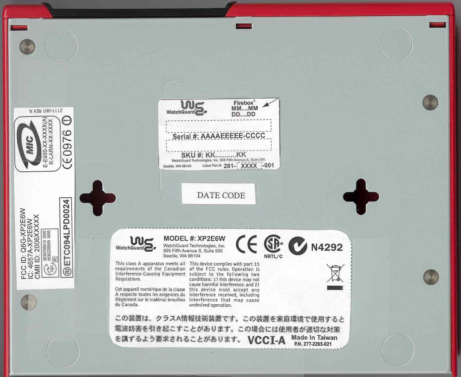
SUBMITTAL PHOTOGRAPH Front SUBMITTAL PHOTOGRAPH Back SUBMITTAL PHOTOGRAPH Top SUBMITTAL PHOTOGRAPH Bottom SUBMITTAL PHOTOGRAPH Left SUBMITTAL PHOTOGRAPH Right
Internal Photos
Page 1 of 6 Report No.: ETS05-043B SUBMITTAL PHOTOGRAPH Inside Front Cover Page 2 of 6 Report No.: ETS05-043B SUBMITTAL PHOTOGRAPH Interior Overall Construction Page 3 of 6 Report No.: ETS05-043B SUBMITTAL PHOTOGRAPH Transmitter Top Page 4 of 6 Report No.: ETS05-043B SUBMITTAL PHOTOGRAPH Transmitter Top without Shield Page 5 of 6 Report No.: ETS05-043B SUBMITTAL PHOTOGRAPH Transmitter Bottom Page 6 of 6 Report No.: ETS05-043B SUBMITTAL PHOTOGRAPH Transmitter Clock
RF Exposure Info
4056 Sierra Pines Dr. * Mariposa, CA 95338 * PH (209) 966-5240 * Fax (209) 742-6133 WORLDWIDE EMC – COMMERCIAL * INDUSTRIAL * MEDICAL * MILITARY * AVIONICS BREA, CA * FREMONT, CA * MARIPOSA, CA *REDMOND, WA Date of Report: 11/15/05 Maximum Permissible Exposure Statement Calculations prepared for: Watchguard Calculations prepared by: Randal Clark CKC Laboratories, Inc. 4056 Sierra Pines Dr. Mariposa, CA 95338 FCC ID Number:: Model Number: Fundamental Operating Frequency: 2402-2462 Maximum Rated Output Power: 26dBm Measured Output Power: 26dBm Measurement Uncertainty: Maximum Antenna Gain: 5.1dBi Power Output and Operating Frequency Information used for these calculations were from: CKC Laboratories, Test Report # Device and Antenna Operating Configuration: Device tested with modulation in continuous transmit mode. Power output listed is conducted with EIRP calculated using manufacturer’s stated antenna gain. The result contained in this report does not include time averaging. Test Procedure: This equipment is evaluated in accordance with the guidelines set forth in OET Guide 65 and RSS 102. Other Considerations: None. 4056 Sierra Pines Dr. * Mariposa, CA 95338 * PH (209) 966-5240 * Fax (209) 742-6133 WORLDWIDE EMC – COMMERCIAL * INDUSTRIAL * MEDICAL * MILITARY * AVIONICS BREA, CA * FREMONT, CA * MARIPOSA, CA *REDMOND, WA MPE Calculations: MPE Limit in accordance with 1.1310: Occupational / Controlled Exposure X General Population / Uncontrolled Exposure MPE Limit = 1.0 (mW/cm 2 ) Note: Limit is calculated based on the lowest frequency used in the operating frequency range. 2 2 4 )/( d EIRP cmmWDensityPower π = Given: EIRP in mW and d in cm EIRP (mW) Distance (cm) Power Density (mW/cm 2 ) Result 1288.25 10.13 1.000 Pass Statement of Compliance: This device demonstrates compliance under the operating conditions specified in this document. Under normal operating conditions, the antenna is designed to be installed in accordance with the manufacturer’s instructions in such a manor to maintain the minimum separation distance. The MPE calculations shown above demonstrate compliance to the provisions of 1.1310 in accordance with the guidelines of OET 65. As can be seen from the MPE results, this device passes the limits specified in 1.1310 at a distance of 10.1cm and at an output power of 1.3 W EIRP under normal operating conditions. This device is not tested for collocation. The antennas used for this transmitter must be installed to provide a separation distance of at least 20 cm from all persons and must not be co-located or operating in conjunction with any other antenna or transmitter. End-users and installers must be provided with antenna installation instructions and transmitter operating conditions for satisfying RF exposure compliance.
Test Report
Page 1 of 99 Report No: FC05-069 WATCHGUARD TECHNOLOGIES, INC. TEST REPORT FOR THE INTERNET FIREWALL, XP2E6W FCC PART 15 SUBPART C SECTIONS 15.247, 15.207 & 15.209, SUBPART B SECTIONS 15.107 & 15.109 CLASS B, SUBPART B SECTION 15.109 CLASS A (DIGITAL) AND RSS-210 COMPLIANCE DATE OF ISSUE: NOVEMBER 11, 2005 PREPARED FOR: Watchguard Technologies, Inc. 505 Fifth Avenue South, Suite 500 Seattle, WA 98104-3892 PREPARED BY: Mary Ellen Clayton CKC Laboratories, Inc. 5046 Sierra Pines Drive Mariposa, CA 95338 P.O. No.: W.O. No.: 251470 83764 Date of test: October 4 - November 10, 2005 Report No.: FC05-069 This report contains a total of 99 pages and may be reproduced in full only. Partial reproduction may only be done with the written consent of CKC Laboratories, Inc. The results in this report apply only to the items tested, as identified herein. Page 2 of 99 Report No: FC05-069 TABLE OF CONTENTS Administrative Information .............................................................................................4 FCC to Canada Standard Correlation Matrix...................................................................5 Conditions for Compliance ..............................................................................................5 Approvals .........................................................................................................................5 Equipment Under Test (EUT) Description ......................................................................6 FCC 15.31(e) Voltage Variation......................................................................................6 FCC 15.31(m) Number Of Channels ...............................................................................6 FCC 15.33(a) Frequency Ranges Tested .........................................................................6 FCC 15.35 Analyzer Bandwidth Settings ........................................................................6 FCC 15.203 Antenna Requirements ................................................................................6 FCC 15.205 Restricted Bands..........................................................................................6 EUT Operating Frequency ...............................................................................................6 Equipment Under Test (EUT) Description ......................................................................7 Equipment Under Test .....................................................................................................7 Peripheral Devices ...........................................................................................................7 Report of Measurements ..................................................................................................9 Table 1: FCC 15.107 Six Highest Conducted Emission Levels ..........................9 Table 2: FCC 15.109 Six Highest Radiated Emission Levels .............................10 Table 3: FCC 15.109 Six Highest Digital Radiated Emission Levels .................11 Table 4: FCC 15.207 Six Highest Conducted Emission Levels ..........................12 FCC 15.247(a)(2) Occupied Bandwidth 6dB ......................................................13 FCC 15.247(a)(2) Occupied Bandwidth 26dB ....................................................19 Table 5: FCC 15.247(b)(2) RF Power Output .....................................................25 Table 6: FCC 15.247(d) Six Highest Spurious Emission Levels ........................26 Table 7: FCC 15.247(d)/15.209 Six Highest Radiated Emission Levels ............27 FCC 15.247(d) Bandedge ....................................................................................28 Table 8: FCC 15.247(e) Peak Power Spectral Density........................................36 Temperature And Humidity During Testing....................................................................43 EUT Setup........................................................................................................................43 Correction Factors............................................................................................................43 Table A: Sample Calculations .............................................................................43 Test Instrumentation and Analyzer Settings ....................................................................44 Spectrum Analyzer Detector Functions ...............................................................44 Peak..........................................................................................................44 Quasi-Peak ...............................................................................................44 Average ....................................................................................................44 EUT Testing.....................................................................................................................45 Mains Conducted Emissions................................................................................45 Antenna Conducted Emissions ............................................................................45 Radiated Emissions ..............................................................................................45 Appendix A: Test Setup Photographs..............................................................................46 Photograph Showing Mains Conducted Emissions .............................................47 Page 3 of 99 Report No: FC05-069 Photograph Showing Mains Conducted Emissions .............................................48 Photograph Showing Radiated Emissions ...........................................................49 Photograph Showing Radiated Emissions ...........................................................50 Photograph Showing Direct Connect Test Setup.................................................51 EUT Setup...............................................................…
Text truncated - open the document above for the full version.
Test Setup Photos
PHOTOGRAPH SHOWING MAINS CONDUCTED EMISSIONS Mains Conducted Emissions - Front View PHOTOGRAPH SHOWING MAINS CONDUCTED EMISSIONS Mains Conducted Emissions - Side View PHOTOGRAPH SHOWING RADIATED EMISSIONS Radiated Emissions - Front View PHOTOGRAPH SHOWING RADIATED EMISSIONS Radiated Emissions - Back View PHOTOGRAPH SHOWING DIRECT CONNECT TEST SETUP
Contact Information
Applicant
Jay Lindenauer(Vice President of Product Delivery Operations)
Technical Contact
CKC Laboratories, Inc.Mary Ellen Clayton
[email protected]800-500-4362
5046 Sierra Pines Drive · Mariposa, California · United States
Test Firm
CKC Laboratories, Inc.Steve Behm
Technical Specifications
| # | Rule Parts | Frequency Range | Power Output |
|---|---|---|---|
| 1 | 15C | 2.41 GHz - 2.46 GHz | 871.00 mW |
Other Applications from WatchGuard Technologies, Inc.
Q6G-AP230W
Mar 12, 2024Wireless Access Point
Equipment Class
NII - Unlicensed National Information Infrastructure TX
Q6G-AP430CR
Jul 08, 2021Wireless Access Point
Equipment Class
DTS - Digital Transmission System
Q6G-AP330
Apr 11, 2021Wireless Access Point
Equipment Class
DTS - Digital Transmission System
Q6G-AP130
Jan 19, 2021Wireless Access Point
Equipment Class
NII - Unlicensed National Information Infrastructure TX
Q6G-FS4AE5W
May 19, 2020Firebox T40-W
Equipment Class
NII - Unlicensed National Information Infrastructure TX