Q6KAT150119AAsset Tracking and Alert Device
3Si Security Systems Inc.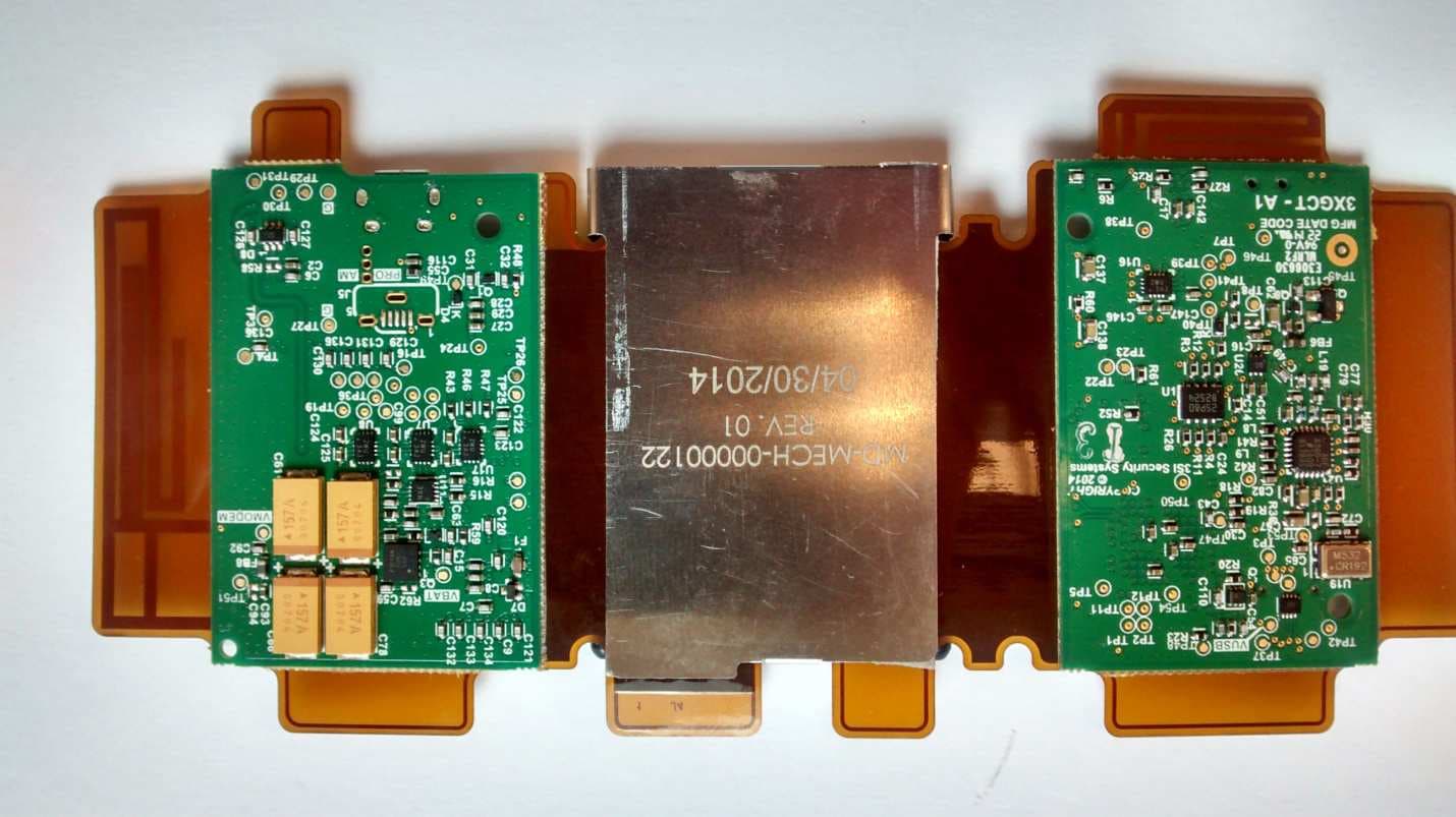
Click to zoom
Application Details
- Equipment Class
- TNB - Licensed Non-Broadcast Station Transmitter
- Date of Grant
- Jun 07, 2015
- Application Purpose
- Original Equipment
- Date of Application
- Jun 07, 2015
- Equipment Note
- Asset Tracking and Alert Device
- Frequency Range
- 216.47500000 - 216.47500000
- Company
- 3Si Security Systems Inc.
- Country
- United States
Documents & Files
Document Text
Text extracted from the exhibit documents filed with the FCC. Open a document above to read the original.
Users Manual
Regulatory Notices Important Safety Information Warning: Use of a non-3SI supplied battery may present a risk of fire, explosion, leakage, or other hazard. • Don’t disassemble, crush, puncture, shred, or otherwise attempt to change the form of your battery. • Don’t use tools, sharp objects, or excessive force to insert or remove the battery as this can damage the battery. • Don’t let the device or battery come in contact with liquids. Liquids can get into the device’s circuits, leading to corrosion • Use with an already tested/certified micro-USB wall charger. Approved external antenna model/ Modèle d'antenne externe agréé: AU-3S-GSM by San Jose Technologies Inc. Gain of 1 dBi Model: AT140317EU, AT140704EU, AT140720EU Declaration of Conformity: This device complies with the essential requirements of Article 3 of the R&TTE 1999/5/EC Directive, if used for its intended purpose, and that the following standards have been applied: 0682 FCC ID: Q6KAT140317A modelAT140317US ID: Q6KAT140704A model AT140704US ID: Q6KAT140720A modelAT140720US ID: Q6KAT140901A modelAT140901US ID: Q6KAT150119A modelAT150119US a.) NOTICE: This device complies with Part 15 of the FCC Rules. Operation is subject 2015-05-12 PN: E99900285 1. Health (Article 3.1a of the R&TTE Directive). Applied standard(s) EC recommendation 1999/519/EC; 2. Safety (Article 3.1a of the R&TTE Directive). Applied standard(s) EN 60950-1: 2006+A11:2009+A1:2010+A2:2013+AC:2011+A12:2011; 3. Electromagnetic compatibility (Article 3.1b of the R&TTE Directive). Applied standards: EN 301 489-1:V1.9.2, -3:V1.4.1, -7:V1.3.1, -24:V1.5.1; 4. Efficient use of the radio frequency spectrum (Article 3.2 of the R&TTE Directive). Applied standards: EN 301 511:V9.0.2, EN 301 908-1:V6.2.1, -2:V5.2.1; EN 300 220-1 & -2:V2.4.1, EN 300 440-1:V1.6.1, -2:V1.4.1 Normas Oficiales Mexicanas Model: AT140317US, AT140704US, AT140720US, AT140901US NOTICE: This device complies with the NOM safety standards: • NOM-001-SCFI-1993 • NOM-003-SCFI-2000 • NOM-016-SCFI-1993 • NOM-019-SCFI-2000 This device complies with Part 15 of the FCC Rules. Operation is subject to the following two conditions: (1) this device may not cause harmful interference, and (2) this device must accept any interference received, including interference that may cause undesired operation. b.) NOTICE: Changes or modifications made to this equipment not expressly approved by 3SI Security System, Inc may void the FCC authorization to operate this equipment. c.) Radio frequency radiation exposure Information: This equipment complies with FCC radiation exposure limits set forth for an uncontrolled environment. This equipment should be installed and operated with minimum distance of 20 cm between the radiator and your body. This transmitter must not be co-located or operating in conjunction with any other (than provided by 3SI) antenna or transmitter. d)NOTICE: This transmitter is authorized by rule under the Low Power Radio Service (47 CFR part 95) and must not cause harmful interference to TV reception or United States Navy SPASUR installations. You do not need an FCC license to operate this transmitter. This transmitter may only be used to provide: auditory assistance to persons with disabilities, persons who require language translation, or persons in educational settings; health care services to the ill; law enforcement tracking services under agreement with a law enforcement agency; or automated maritime telecommunications system (AMTS) network control communications. Two-way voice communications and all other types of uses not mentioned above are expressly prohibited. e.)NOTICE: This device may not interfere with TV reception or Federal Government radar. Model: AT140317EU NOTICE: This device complies with the requirements imposed or covered by regulations in Australia and New Zealand. Regulatory Notices Important Safety Information Warning: Use of a non-3SI supplied battery may present a risk of fire, explosion, leakage, or other hazard. • Don’t disassemble, crush, puncture, shred, or otherwise attempt to change the form of your battery. • Don’t use tools, sharp objects, or excessive force to insert or remove the battery as this can damage the battery. • Don’t let the device or battery come in contact with liquids. Liquids can get into the device’s circuits, leading to corrosion • Use with an already tested/certified micro-USB wall charger. Approved external antenna model/ Modèle d'antenne externe agréé: AU-3S-GSM by San Jose Technologies Inc. Gain of 1 dBi c.) Radio frequency radiation exposure Information: This equipment complies with IC radiation exposure limits set a.) NOTICE: This device complies with RSS-210 of Industry Canada. Operation ID: 5043A-AT140317A, model : AT140317US ID: 5043A-AT140704A, model: AT140704US ID: 5043A-AT140720A, model : AT140720US ID: 5043A-AT140901A, model : AT140901US INDUSTRY CANADA 2015-05-12 PN: E99900285 This equipment complies with IC radiation exposure limits set forth for an uncontrolled environment. This equipment should be installed and operated with minimum distance of 20 cm between the radiator and your body. This transmitter must not be co-located or operating in conjunction with any other antenna or transmitter. Cet équipement est conforme aux exigences d’exposition aux radiofréquences de la IC pour un environnement non contrôlé. Il devrait être installé et opéré d'une distance minimum de 20 cm entre le radiateur et votre corps. Le transmetteur ne doit pas être situé ou opéré en conjonction avec une autre antenne ou transmetteur. d.) Antenna Statement Under Industry Canada regulations, this radio transmitter may only operate using an antenna of a type and maximum (or lesser) gain approved for the transmitter by Industry Canada. To reduce potential radio interference to other users, the antenna type and its gain should be so chosen that the equivalent isotropically radiated power (e.i.r.p.) is not more than that necessary for successful communication. Conformém…
Text truncated - open the document above for the full version.
Cover Letter(s)
May 27, 2015 Federal Communications Commission 445 12 th Street SW Washington, DC 20554 Subject: Limited Agency Agreement 3SI Security Systems FCC ID: Q6KAT150119A To Whom It May Concern: We, 3SI Security Systems, hereby authorized Intertek Testing Services to act as our Agent for the purpose of preparing application for FCC ID number Q6KAT150119A under all applicable parts of the FCC rules and regulations. The effective date of this limited agency agreement is May 27, 2015. The Limited Agency Agreement expires on Aug 31, 2015, unless sooner terminated or extended by written notice to Intertek Testing Services and the Federal Communications Commission. This is to advise that we are in full compliance with the Anti-Drug Abuse Act. The applicant is not subject to a denial of federal benefits pursuant to Section 5301 of the Anti-Drug Act of 1988, 21 U.S.C. 862, and no party to the application is subject to a denial of federal benefits pursuant to that section. If you have any questions or comments, please do not hesitate to contact me. Sincerely, ______________________ Brandon Cromer Technical Mgr of Hardware & Systems
Cover Letter(s)
Federal Communications Commission Equipment Authorization Division, Application Processing Branch 7435 Oakland Mills Road Columbia, MD 21048 May 18, 2015 Dear FCC Examiner, Pursuant to Paragraphs §0.457 and §0.459 of the Commission’s Rules (47 C.F.R.) and Section §522(b)(4) of the Freedom of Information Act, 3SI Security Systems Inc. requests permanent confidentiality granted for the following product: FCC ID Title/Model Q6KAT150119A AT150119US For the product stated above, we request that the following information be held confidential: 1) Block diagram and operational description 2) Schematics 3) Parts list The items listed above contain 3SI Security Systems trade secrets and proprietary information that is otherwise not available to the public. Should you have any questions, please contact me at the address below. Regards, __________________________ ___________________ Brandon Cromer Date 3SI Security Systems 101 Lindenwood Drive Suite 200 Malvern, PA 19355 May 18, 2015
External Photos
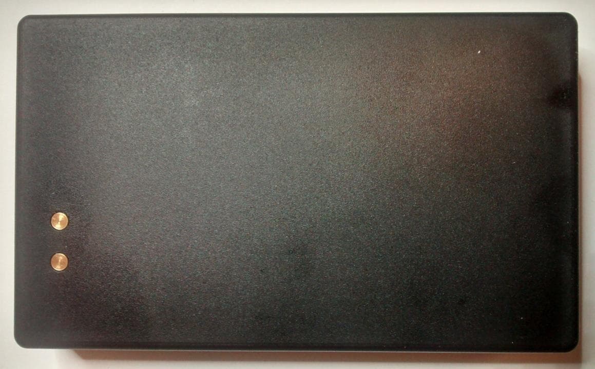
FCC ID: Q6KAT150119A EXTERNAL PHOTOGRAPHS 1. Top side view of the radio product. FCC ID: Q6KAT150119A 2. Bottom side view of the radio product.
ID Label/Location Info
FCC ID: Q6KAT150119A PRODUCT LABEL LOCATION Product label is located under the battery. The expanded view of the label is shown below:
Internal Photos
FCC ID: Q6KAT150119A INTERNAL PHOTOGRAPHS 1. Top side view of the radio product with the battery removed. For detailed internal view of the module, see: FCC ID: RI7CE910DUAL JF2 module with the shield removed FCC ID: Q6KAT150119A 2. Enlarged view of the board showing JF2 module with the shield removed. FCC ID: Q6KAT150119A 3. Bottom side view of the radio product, with the battery holder removed. There are no shields on this side.
RF Exposure Info
731 Enterprise Drive Lexington, KY 40510 Telephone: 859-226-1000 Facsimile: 859-226-1040 www.intertek-etlsemko.com MPE Calculation § 1.1310: The criteria listed in table 1 shall be used to evaluate the environmental impact of human exposure to radiofrequency (RF) radiation as specified in §1.1307(b), except in the case of portable devices which shall be evaluated according to the provisions of §2.1093 of this chapter. Part 1.1310 Limits for Maximum Permissible Exposure (MPE) 1.1 Test Procedure An MPE evaluation for was performed in order to show that the device was compliant with §2.1091. The maximum power density was calculated for each transmitter at a separation distance of 20cm. For each transmitter the maximum RF exposure at a 20 cm distance using the formula: 10/)( 10 dBmowerConductedP mW PowerConducted= 2 )20(4 . cm mW GainAntPowerConducted tyPowerDensi × × = π 731 Enterprise Drive Lexington, KY 40510 Telephone: 859-226-1000 Facsimile: 859-226-1040 www.intertek-etlsemko.com 1.2 Results: • Maximum Conducted Output Power = 10.63dbm • Maximum Antenna Gain = -36.4dbi Power Density = (10.63dBm+ -36.4dbi) / 5025.6 cm 2 Power Density = 0.0026mW / 5025.6 cm 2 Power Density = . 0.0000005 mW/cm 2 Limit at 216.475 = 0.2mW/cm 2 The calculated maximum power density at 20cm distance is less that the limit for general population / uncontrolled exposure.
Test Report
FCC ID: Q6KAT150119A ANTENNA INFORMATION This radio product is equipped with 1. Data modem antenna, connected to FCC certified transmitter RI7 1.1 Physical properties. The modem antenna is an inverted F type, printed on the flex board attached to the edge of the modem module ( 1.2 Frequency coverage BAND 1 2 Q6KAT150119A ANTENNA INFORMATION is equipped with internal, non-detachable antennas characterized below. Data modem antenna, connected to FCC certified transmitter RI7CE910DUAL The modem antenna is an inverted F type, printed on the flex board attached to the edge of the modem module (RI7CE910DUAL) Frequency coverage BAND LOW BANDEDGE HIGH BANDEDGE MHz MHz 806 960 1710 2170 characterized below. DUAL. The modem antenna is an inverted F type, printed on the flex board attached to the edge of FCC ID: Q6KAT150119A 1.3 Impedance 1.4 Antenna Gain BAND Gain dBi 1 2.4 2 2.8 FCC ID: Q6KAT150119A 2. Beacon antenna 2.1 Physical properties. The beacon antenna is implemented as a closed loop (a trace) around the PCB perimeter. The total length of the trace is: 2.2 Frequency coverage. Q6KAT150119A Physical properties. The beacon antenna is implemented as a closed loop (a trace) around the PCB perimeter. The length of the trace is: 16.363” Frequency coverage. LOW BANDEDGE HIGH BANDEDGE MHz MHz 210 240 The beacon antenna is implemented as a closed loop (a trace) around the PCB perimeter. The FCC ID: Q6KAT150119A 2.3 Measured impedance 2.4 Antenna Gain FREQUENCY Gain MHz dBi 216.475 -36.4 219.600 -35.2
Test Report
This report is for the exclusive use of Intertek's Client and is provided pursuant to the agreement between Intertek and its Client. Intertek's responsibility and liability are limited to the terms and conditions of the agreement. Intertek assumes no liability to any party, other than to the Client in accordance with the agreement, for any loss, expense or damage occasioned by the use of this report. Only the Client is authorized to permit copying or distribution of this report and then only in its entirety. Any use of the Intertek name or one of its marks for the sale or advertisement of the tested material, product or service must first be approved in writing by Intertek. The observations and test results in this report are relevant only to the sample tested. This report by itself does not imply that the material, product, or service is or has ever been under an Intertek certification program. EMC Report for 3SI Security Systems on the AT150119US Page 1 of 26 731 Enterprise Drive Lexington, KY 40510 Telephone: 859-226-1000 Facsimile: 859-226-1040 www.intertek-etlsemko.com TEST REPORT Report Number: 102092861LEX-001 Project Number: G102092861 Report Issue Date: 5/21/2015 Product Name: AT150119US Standards: Title 47 CFR Part 15 Subpart B and Part 95 Tested by: Client: Intertek Testing Services NA, Inc. 731 Enterprise Drive Lexington, KY 40510 3SI Security Systems 2055 N. Brown Road, Suite 225 Lawrencefille, GA 30043 Report prepared by Report reviewed by Bryan Taylor, Team Leader Jason Centers, Staff Engineer Intertek Report Number: 102092861LEX-001 Issued: 5/21/2015 EMC Report for 3SI Security Systems on the AT150119US Page 2 of 26 TABLE OF CONTENTS 1 Introduction and Conclusion .............................................................................................................. 3 2 Test Summary ...................................................................................................................................... 3 3 Description of Equipment Under Test ............................................................................................... 4 4 Maximum Transmitter Output Power ................................................................................................. 7 5 Occupied Bandwidth ........................................................................................................................... 9 6 Conducted Spurious Emissions at Antenna Terminals ................................................................. 12 7 Radiated Spurious Emissions (Transmitter) ................................................................................... 15 8 Frequency Stability ............................................................................................................................ 19 9 Receiver Spurious Emissions .......................................................................................................... 21 10 Measurement Uncertainty.............................................................................................................. 25 11 Revision History ............................................................................................................................. 26 Intertek Report Number: 102092861LEX-001 Issued: 5/21/2015 EMC Report for 3SI Security Systems on the AT150119US Page 3 of 26 1 Introduction and Conclusion The tests indicated in section 2 were performed on the product constructed as described in section 3. The remaining test sections are the verbatim text from the actual data sheets used during the investigation. These test sections include the test name, the specified test method, a list of the actual test equipment used, documentation photos, results and raw data. No additions, deviations, or exclusions have been made from the standard(s) unless specifically noted. Based on the results of our investigation, we have concluded the product tested complied with the requirements of the standard(s) indicated. The results obtained in this test report pertain only to the item(s) tested. The INTERTEK-Lexington is located at 731 Enterprise Drive, Lexington Kentucky, 40510. The radiated emission test site is a 10-meter semi-anechoic chamber. The chamber meets the characteristics of CISPR 16-1 and ANSI C63.4. For measurements, a remotely controlled flush-mount metal-top turntable is used to rotate the EUT a full 360 degrees. A remote controlled non-conductive antenna mast is used to scan the antenna height from one to four meters. The test site is listed with the FCC under registration number 485103. The test site is listed with Industry Canada under site number IC 2042M-1. 2 Test Summary Page Test full name FCC Reference Result 7 Maximum Transmitter Output Power 2.1046, 95.639(e) Pass 9 Occupied Bandwidth 2.1049, 95.629(c) Pass 12 Conducted Spurious Emissions 2.1051, 95.635(c)(2) Pass 15 Radiated Spurious Emissions (Transmitter) 2.1053, 95.635(c)(2 Pass 19 Frequency Stability 2.1055, 95.629(c)(2) Pass 21 Receiver Spurious Emissions 15.109 Pass --- Conducted Voltage Emissions 15.107 NA 1 1 This test was not applicable since the test sample was battery powered and would never have any connections to the AC mains. Intertek Report Number: 102092861LEX-001 Issued: 5/21/2015 EMC Report for 3SI Security Systems on the AT150119US Page 4 of 26 3 Description of Equipment Under Test Equipment Under Test Manufacturer 3SI Security Systems Model Number AT150119US Serial Number 5773143697 Receive Date 5/12/2015 Test Start Date 5/12/2015 Test End Date 5/15/2015 Device Received Condition Good Test Sample Type Production Frequency Band 216.475MHz Modulation Type None Transmission Control Test Commands Maximum Output Power (Conducted) 10.63dBm Test Channels LPRS Channel 50 (Extra Band Frequencies) Antenna Type PCB / Internal Operating Voltage 3.7VDC (Battery) Description of Equipment Under Test The AT150119US is an asset tracking and alert device equipped with a cellular transmitter module, GPS receiver, …
Text truncated - open the document above for the full version.
Test Setup Photos
Test Setup Test Setup
Contact Information
Applicant
Brandon Cromer(Systems and Technical Manager)
Technical Contact
3SI SECURITY SYSTEMS INC.Waldemar Sierocinski
[email protected]470-223-0804
2055 N Brown Road · Lawrenceville · United States
Test Firm
Intertek Testing Services NAJames Sudduth
Technical Specifications
| # | Rule Parts | Frequency Range | Power Output | Emission | Tolerance |
|---|---|---|---|---|---|
| 1 | 95G | 216.475 MHz - 216.475 MHz | 2.00 µW | 681HP0N | 0.2500000000 ppm |
Other Applications from 3Si Security Systems Inc.
Q6KAT140720A
Jan 27, 2015Asset Tracking and Alert Device
Equipment Class
PCB - PCS Licensed Transmitter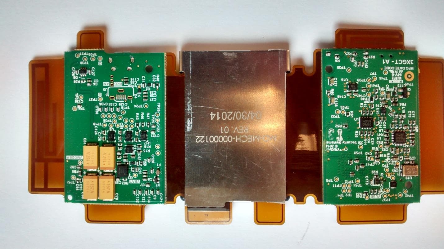
Q6KAT140901A
Dec 18, 2014Asset Tracking and Alert Device
Equipment Class
PCB - PCS Licensed Transmitter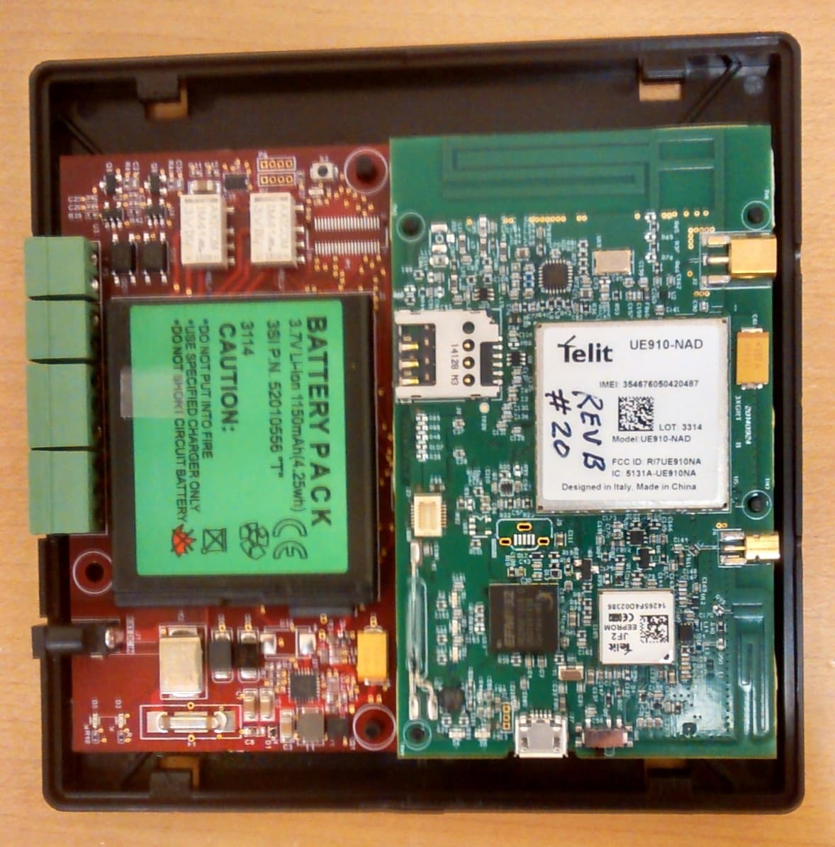
Q6KAT140704A
Dec 07, 2014Asset Tracking and Alert Device
Equipment Class
PCB - PCS Licensed Transmitter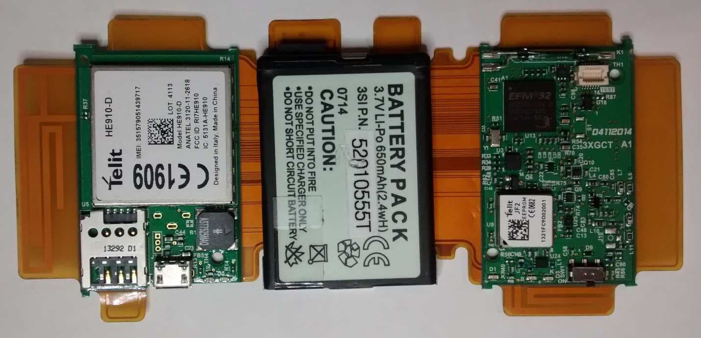
Q6KAT140317A
Jul 10, 2014Asset Tracking and Alert Device
Equipment Class
PCB - PCS Licensed Transmitter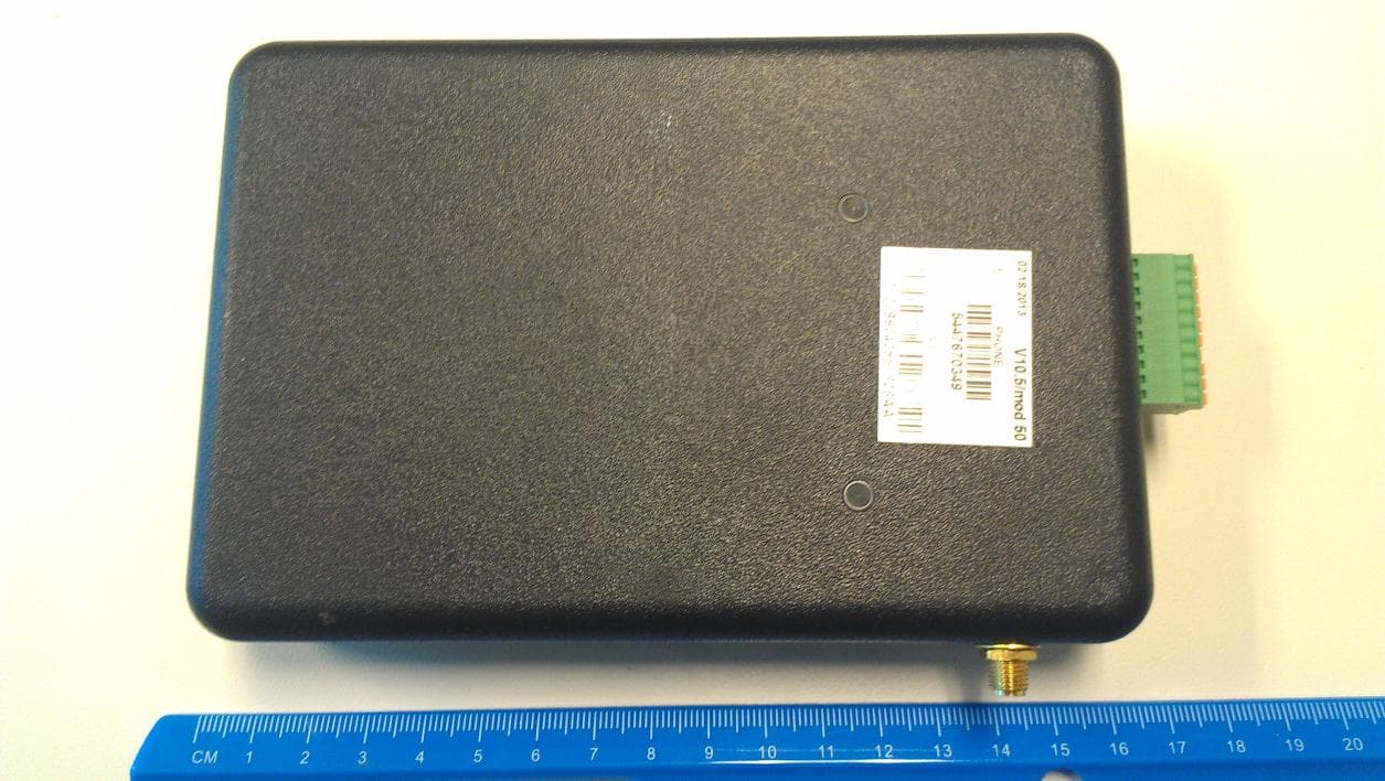
Q6KGT86000A
May 02, 2013ASSET TRACKING AND ALERT DEVICE
Equipment Class
PCB - PCS Licensed Transmitter