Q6U-MCR-001Bluetooth gateway
Yantouch Corporation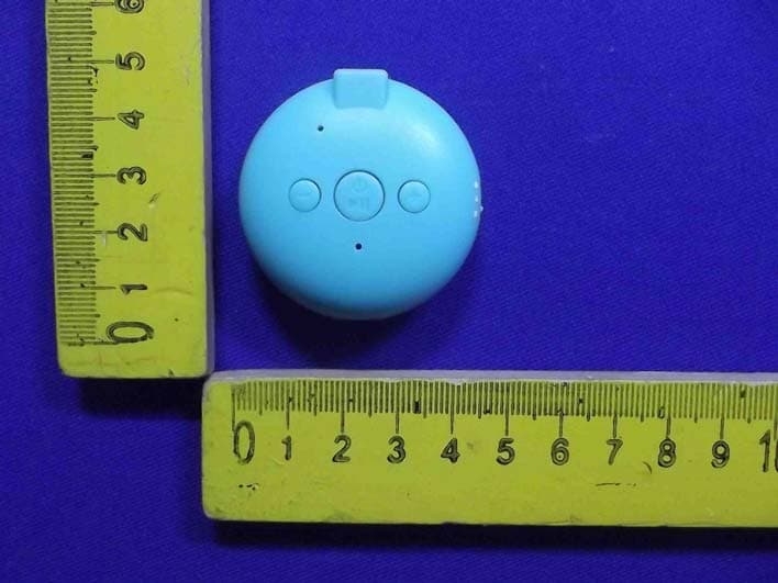
Click to zoom
Application Details
- Equipment Class
- DSS - Part 15 Spread Spectrum Transmitter
- Date of Grant
- Mar 16, 2014
- Application Purpose
- Original Equipment
- Date of Application
- Mar 16, 2014
- Equipment Note
- Bluetooth gateway
- Frequency Range
- 2402.00000000 - 2480.00000000
- Company
- Yantouch Corporation
- Country
- Taiwan
Documents & Files
Document Text
Text extracted from the exhibit documents filed with the FCC. Open a document above to read the original.
Users Manual
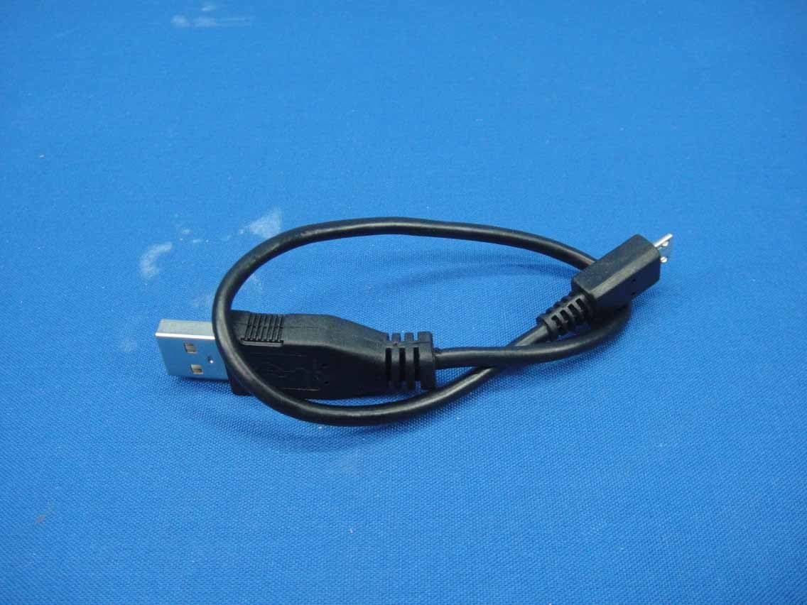
Introduction: With the trend of large-size mobile phone, it sounds no longer convenient to have one really taken in hand. More and more users choose to leave mobile phone in their bag. Considering the trend, the wearable MCR-1 in a fashion shape is introduced to the market. It connects to smart phone through Bluetooth technology. When users take it, the MCR-1 prevents smart phone from dropping and brings followingbenefits. Anti-loss reminder: the MCR-1 reminds users with a vibration alert when itis away from their mobilephonesforcertaindistance*. Phonecallreminder:theMCR-1givesavibrationalertwhenthereisanincomingcall. Hands-free conversation: the MCR-1 equips with a microphone, let users answer the incoming callwheninsertinganearphone. Portablemusicplayer:users canlisten tostereomusic frommobilephone withinsertedearphone, andplay/selectsongandadjustvolumethroughtheMCR-1. Inaddition, applying amale-to-maleaudio linetoconnect theMCR-1and aconventional Hi-Fispeaker canmaketheHiFiBluetoothenabled. Upgraded Hi-Fi speaker: With an audio line, MCR-1 connects to LINE IN jack of the speaker to transmit music. The speaker can play stereo music from mobile phone under the control of the MCR-1. *5metersinaverage,dependingontheenvironment. HumanInterface 1. ModeSelection: (a) NormalMode:MCR-1fullyoperatedwith5-hourtalkingtimeand7-daystandbytime. (b) SilentMode:WorkasitdoesinNormalModeexceptvibrationfunctionisdisabled. (c) VeryLowPowerMode:ItmakesMCR-1canbestoredforyearswithafully-chargedbattery. NotedthatMCR-1willworkasitisinNormalModewhenchargingevenitisintheVery LowPowerMode.TheVeryLowPowerModelalsoresetthewholeunit. Note:AfteranychangeinModeSelection,usershavetopushMFBtorestartMCR-1. 2. 3.5mm Phone Jack: It connects to earphone. Note that MCR-1 does not support microphone function of the earphone. It also connects a male-to-male Audio Line to theLINE IN jack of a conventionalHi-Fispeaker,tomakeitBluetoothenabled. 3. Strap Hole: With Accessory Metal Ring, it enables users to have wider choices of straps. The BiggerandSmallerStrapRingaresuggestedtobeconnectedasshown. 4. mini USB Connector: MCR-1 will be charged when it isconnected toa DC-5V power source with theAccessoryChargingCable. 1 (a) (b) (c) 3 2 5 6 7 Bigger Strap Ring Smaller Strap Ring 4 Macaron 1 (a) (b) (c) 3 2 5 6 7 Bigger Strap Ring Smaller Strap Ring 4 Macaron 1 (a) (b) (c) 3 2 5 6 7 Bigger Strap Ring Smaller Strap Ring 4 Chaton 1 (a) (b) (c) 3 2 5 6 7 Bigger Strap Ring Smaller Strap Ring 4 Chaton 5. Microphone:Usedforhand-freeconversation. 6. LED: Upper Red and lower Blue LEDs, indicate the status for user operation. In this user guide, LED1denotestheupperLED,andLED2denotesthelowerLED. 7. OperationButtons:-,MFB,+. Operation-MFB+ PushVolume Down Play/PauseVolume Up Long PushBackwardStopForward PushVolume DownAnswerVolume Up Long PushReject PushVolume DownCancelVolume Up Long PushCancel PushVolume DownCancelVolume Up Long PushCancel "Conversation" "StandBy" "Incoming Call" "Dialing" Instruction: 1. Power ON: Push MFB for 3 sec, both LEDs will flash 3 times with 1 vibration,and a "power on"voicefromthePhoneJack. 2. PowerOFF: PushMFBfor3secinanyotherstates,bothLEDswillflash3timeswith1vibration, anda"poweroff"voicefromthePhoneJack. 3. Battery Low: LED1 will flash 2 times with 1 vibration, and a "Battery Low"voice from the PhoneJack. 4. Under Charging: MCR-1 will be charged when it connects the charging cabletoaDC-5Vpower source.Thechargingtimeis2hourstypically.TheLED1keepsonwhenitisundercharging. 5. TalkingTime:Typicallynolessthan5hoursnomatterwhenlistentomusicorphoneconversation. 6. Stand-ByTime:Typically7dayswhenstayinStand-Bystate. 7. PairingandConnect: (a) NeverPairingBefore: (a-1) Push MFB longer than 5 sec will start the Pairing. Both LEDs will flashalternatively, anda"pairing"voicefromthePhoneJack. (a-2)TurnontheBluetoothofthemobilephoneandseekforthedevicenamed“MCR-1". (a-3) Go pairing MCR-1 through mobile phone. If mobile phones ask for a matching code, key in 0000. When complete the pairing, LED2 will flash 10 times, and a "pairing completed"voicefromthePhoneJack. (a-4) Go connecting MCR-1 through mobile phone. When they are successfully connected, LED2 will flash 2 times with 1 vibration, and enter the Stand-By state. LED2keeps flashing2timespersecondsintheStand-Bystate. (a-5)IfthePairingisnotsuccessful, avoice"pairingnotcompleted"willbesentfromthe PhoneJack.Follow(a-1)~(a-4)torepeatthe“PairingandConnect"again. (b)EverPaired: (b-1)WhenMCR-1isinPower-Onstate,pushMFBtoconnectthemobilephone. (b-2) When MCR-1 is in Power-Off state, turn it on by pushing MFB longer than3sec,to connectthemobilephone. 8.AnswerPhoneCall:MCR-1willvibratewith1secdurationsuccessivelyintheIncomingCallstate. 8.1 Answer with MCR-1: Push MFB, then a hand-free conversation can start with the embedded microphone when an earphone is inserted. (Note: MCR-1 does not support themicrophone functionoftheearphone.) 8.2 Answer with mobile phone: It will depend on the Bluetooth function provided by different mobile phones. If the mobile phone cannot answer the phone call well, usersneed to switch MCR-1 into Very Low Power Mode before answer incoming call. Then, turn it back to either NormalModeorSilentModeafterthephonecall,andrestartMCR-1. 9. RejectPhoneCall:PushMFBlongerthan2secwhenusersarenotconvenienttoanswercall. 10. Anti-loss: Whenever MCR-1 detectsthe connected Bluetooth signal lower than some level (typically 3m ~ 5m*), it successively vibrates 3 times with 2-sec durationuntil it loses the Bluetoothsignal(typically10m*). *Dependontheenvironment. 11.OneMCR-1sharedby2mobilephones 11.1 FollowInstruction7toletMCR-1pairedwithPhoneAandPhoneBrespectively. 11.2 TurnoffBluetoothofPhoneAandPhoneB. 11.3 FollowInstruction7(b),connectMCR-1toPhoneA. 11.4 Follow Instruction 7(b), connect MCR-1 to Phone B. Then, both Phone A and Phone B are connectedtoMCR-1. Accessory 1. AudioLine: Used to connect MCR-1 to LINE IN jack of the conventional Hi-Fispeaker. (ItisonlyprovidedinMaca…
Text truncated - open the document above for the full version.
Cover Letter(s)
Yantouch Corporation Mar. 10, 2014 Federal Communications Commission Authorization and Evaluation Division Confidentiality Request regarding application for certification of FCC ID:Q6U-MCR-001. Pursuant to Sections 0.457 and 0.459 of the Commission’s Rules, we hereby request confidential treatment of information accompanyingthis application as outlined below: Exhibit TypeFile Name Block DiagramBlockDiagram.pdf Schematic DiagramSchematics.pdf Circuit DescriptionCircuit Description.pdf The above materials contain trade secrets and proprietary information not customarily released to the public. The public disclosure of these materials may be harmful to the applicant and provide unjustified benefits to its competitors. Yours Sincerely, Yantouch Corporation <SIGNATURE of John Hsu> ---------------------------------------------------------- R&D Director
Cover Letter(s)
Yantouch Corporation FCC ID: Q6U-MCR-001 POWER OF ATTORNEY (03/10/2014) Federal Communications Commission Authorization and Evaluation Division 7435 Oakland Mills Road Columbia, MD 21046 To Whom It May Concern: We, the undersigned, hereby authorize Shenzhen Anbotek Compliance Laboratory Limited (MR. Tom Chen, Manager) on our behalf, to apply to the Federal Communications Commission on our equipment. Any and all acts carried out by Shenzhen Anbotek Compliance Laboratory Limited (MR. Tom Chen, Manager) on our behalf shall have the same effect as acts of our own. This authorization expires on(03/10/2015). This is to advise that we are in full compliance with the Anti-Drug Abuse Act. We,(Yantouch Corporation), are not subject to a denial of federal benefits pursuant to Section 5301 of the Anti-Drug Act of 1988, 21 USC853a, and no party to the application is subject to a denial of federal benefits pursuant to that section. Sincerely, (Yantouch Corporation) ------------------------------- (John Hsu) (R&D Director)
Cover Letter(s)
NINGBO EMTEK CO., LTD. Statement Mar. 10, 2014 Federal Communications Commission Authorization and Evaluation Division 7435 Oakland Mills Road Columbia, MD 21046 To Whom It May Concern: We, NINGBO EMTEK CO., LTD. (Address: 1F Building 4, 1177#, Lingyun Road, Ningbo National Hi-Tech Zone, Ningbo, Zhejiang, China) declare for the equipment identified by: Product Description: Bluetooth gateway Model Number: MCR-001, MCR-002, MCR-003, MCR-004, MCR-005, MCR-006, MCR-007, MCR-008, MCR-009 Tradename or Brands: N.A. FCC ID: Q6U-MCR-001 We confirm that all the tests for this product according to FCC PART 15.247 were conducted in our test lab. Yours Sincerely, ---------------------------------------------------------- Andy Wang/ Manager NINGBO EMTEK CO., LTD. Tel: 86-574-27907998 Fax: 86-574-27721538
External Photos
Figure 1 The EUT-Overall View Figure 2 The EUT- Front View Figure 3 The EUT- Back View Figure 4 TheEUT-SideView Figure 5 TheEUT-SideView
ID Label/Location Info
Product Name:Bluetooth gateway Model No.:MCR-001 FCC ID:Q6U-MCR-001
ID Label/Location Info
Label Location On EUT
Internal Photos
Figure 6 The EUT-Inside View Figure 7 PCB of the EUT-Front View Figure 8 PCB of the EUT-Front View Figure 9 PCB of the EUT-Back View Figure 10 PCB of the EUT-Front View Figure 11 PCB of the EUT-Back View
Operational Description
MY81SPK02M2 Datasheet v0.2 MY81SPK02M2 5 Http://www.myland.com.hk MY81SPK02M2 Bluetooth 3.0+EDR Stereo Audio module MY81SPK02M2 Datasheet v0.2 MY81SPK02M2 5 Http://www.myland.com.hk 1. General Description The MY81SPK02M2 Bluetooth module is designed using the ISSC IS1681S chip. The module is highly integrated, compact size, low power and high data rate. It requires very few external components to achieve high quality stereo audio streaming with remote control commands. The MY81SPK02M2 provides remote control keys, operation status indication pins, stereo audio output, AUX input interface and NFC detection interface. 2. Features 1. Bluetooth 3.0+EDR compliant 2. Typical +2dBm Class 2 output power 3. Audio DAC: 94dB SNR 4. Build in Max. 250mAH Li-ion battery charging circuit 5. HSP, HFP, A2DP, AVRCP profile support 6. SBC decode for Bluetooth audio streaming 7. Voice prompt 8. Build in Line in interface 9. Build in MIC circuit 10. AGC/AVC,AEC 11. NFC support 12. EQ control 13. Size: 13.5mm x 26.8mm MY81SPK02M2 Datasheet v0.2 MY81SPK02M2 5 Http://www.myland.com.hk 3. Application High quality stereo headset High quality stereo speaker and HiFi High quality wireless stereo audio receiver 4. Outline Dimension & Pin Definition MY81SPK02M2 Datasheet v0.2 MY81SPK02M2 5 Http://www.myland.com.hk Pin No. I/O Name Description 1 I/O P20 GPIO, default pull-high input System Configuration, H: Application L: Baseband(IBDK Mode) 2 P P30 GPIO, default pull-high input Line-in detection, 1: no line-in detected; 0: line-in detected 3 I/O P00 GPIO, default pull-low input. Slide Switch Detector 4 I/O P04 GPIO, default pull-high input Audio AMP Enable or NFC detect 5 AO SPKR R-channel analog headphone output, single-ended application only 6 AO AOHPM Headphone common mode output/sense input 7 AO SPKL L-channel analog headphone output, single-ended application only 8 AP VDDA Reserve for external cap to fine tune audio frequency response 9 AP AGND Audio ground 10 AI MIC1_P Mic 1 mono differential analog positive input 11 AI MIC1_N Mic 1 mono differential analog negative input 12 AP MIC_BIASMicrophone biasing voltage 13 AI AIR Stereo analog line in, R-channel 14 AI AIL Stereo analog line in, L-channel 15 I/O RST_N System Reset Pin 16 P ADAP_IN Power adaptor input 17 P VDDIO VDDIO pin, for calibration only Do not add external power to this pin 18 P BAT_IN Battery input 19 P SYS_PW System Power Output 20 I/O SK1/P03 Default SAR input for battery detection This pin can be re-defined as GPIO P03 21 P GND Digital ground 22 P BK_OUT Buck feedback sense pin 23 P MFB Multi-Function Push Button key Combined Play/Pause key when A2DP enabled. 24 P LED1 LED Driver 1 25 P LED2 LED Driver 2 26 I/O P02 GPIO, default pull-high input PLAY/PAUSE button 27 I/O P27 GPIO, default pull-high input,Forward button MY81SPK02M2 Datasheet v0.2 MY81SPK02M2 5 Http://www.myland.com.hk 28 I/O P05 GPIO, default pull-high input,REW button 29 O HCI_TXD HCI TX data 30 I HXI_RXD HCI RX data 31 I/O P16 GPIO, default pull-high input Volume down button 32 I/O P01 GPIO, default pull-high input Volume up button 33 AIO BT_RF/P22 NC for on board PCB antenna/ Audio AMP Enable Antenna matching if an external antenna is used 34 P GND Digital ground 5. BQB Approval Revision History Version Date Description V0.1 2012-9-10 First draft V0.2 2012-10-10 QDID added ===================================================================== Contact us: Myland Limited Rm.3, 3/F., Block B, Tonic Ind. Centre, 19 Lam Hing Street, Kowloon Bay, Kowloon, Hong Kong Tel:852-23312212 Fax:852-27573135。E-Mail:[email protected] Http://www.myland.com.hk
Test Report
Shenzhen Anbotek Compliance Laboratory Limited FCC ID: Q6U-MCR-001 Page 1 of 54 Report No.: 201402776F Shenzhen Anbotek Compliance Laboratory Limited Tel:(86)755-26066544 Fax:(86)755-26014772 www.anbotek.com FCC TEST REPORT for Yantouch Corporation Bluetooth gateway Model No.: MCR-001, MCR-002, MCR-003, MCR-004, MCR-005, MCR-006, MCR-007, MCR-008, MCR-009 Report Number : 201402776F Date of Test : Feb. 22~ Mar. 05, 2014 Date of Report : Mar. 06, 2014 Prepared for : Yantouch Corporation Address : Rm. 303, 4F-1., No.5, Xin'an Rd., Hsinchu Science, Hsinchu City 300, Taiwan Prepared By : Shenzhen Anbotek Compliance Laboratory Limited Address : 1/F., Building 1, SEC Industrial Park, No.0409 Qianhai Road, Nanshan District, Shenzhen, Guangdong, China Tel: (86) 755-26066544 Fax: (86) 755-26014772 Shenzhen Anbotek Compliance Laboratory Limited FCC ID: Q6U-MCR-001 Page 2 of 54 Report No.: 201402776F Shenzhen Anbotek Compliance Laboratory Limited Tel:(86)755-26066544 Fax:(86)755-26014772 www.anbotek.com TABLE OF CONTENTS Description Page Test Report 1. GENERAL INFORMATION ................................................................................................................ 5 1.1 Description of Device (EUT) ....................................................................................................................... 5 1.2 Auxiliary Equipment Used during Test ......................................................................................................... 6 1.3 Description of Test Facility .......................................................................................................................... 6 1.4 Measurement Uncertainty ............................................................................................................................ 6 2. TEST PROCEDURE ............................................................................................................................ 7 3. CONDUCTED EMISSION ................................................................................................................... 8 3.1 Block Diagram of Test Setup ....................................................................................................................... 8 3.2 Power Line Conducted Emission Measurement Limits (15.207) ................................................................... 8 3.3 Configuration of EUT on Measurement ....................................................................................................... 8 3.4 Operating Condition of EUT ........................................................................................................................ 8 3.5 Test Procedure ............................................................................................................................................. 9 3.6 Power Line Conducted Emission Measurement Results ............................................................................... 9 4. RADIATION INTERFERENCE ......................................................................................................... 12 4.1 Requirements (15.247, 15.209): ................................................................................................................. 12 4.2 Test Procedure ........................................................................................................................................... 12 4.3 Test Configuration ..................................................................................................................................... 13 4.4 Test Results ............................................................................................................................................... 14 5. CHANNEL SEPARATION TEST ........................................................................................................ 23 5.1 Measurement Procedure ............................................................................................................................ 23 5.2 Test SET-UP .............................................................................................................................................. 23 5.3 Test Equipment .......................................................................................................................................... 23 5.4 Test Results ............................................................................................................................................... 24 6. 20DB BANDWIDTH TEST ................................................................................................................. 28 6.1 Measurement Procedure ............................................................................................................................ 28 6.2 Test SET-UP .............................................................................................................................................. 28 6.3 Test Equipment .......................................................................................................................................... 28 6.4 Test Results ............................................................................................................................................... 28 7. QUANTITY OF HOPPING CHANNEL TEST ..................................................................................... 33 7.1 Measurement Procedure ............................................................................................................................ 33 7.2 Test SET-UP .............................................................................................................................................. 33 7.3 Test Equipment .......................................................................................................................................... 33 7.4 Test Results .........................................................................…
Text truncated - open the document above for the full version.
Test Setup Photos
1. Photo of Power Line Conducted Emission Test 2.Photo of Radiated Emission Test
Contact Information
Applicant
John Hsu(R&D Director)
Test Firm
EMTEK (NINGBO) CO.,LTD.Andy Wang
Technical Specifications
| # | Rule Parts | Frequency Range | Power Output |
|---|---|---|---|
| 1 | 15C | 2.40 GHz - 2.48 GHz | 1.50 mW |
Other Applications from Yantouch Corporation
Q6U-YTL110-112-12
Dec 17, 2015EYE1 (Black or White)
Equipment Class
DSS - Part 15 Spread Spectrum Transmitter
Q6U-YTL091-911-16
Aug 08, 2013Bluetooth Speaker
Equipment Class
DSS - Part 15 Spread Spectrum Transmitter
Q6U-YTL051-XYZ
Oct 29, 2012BlackDiamond3
Equipment Class
DSS - Part 15 Spread Spectrum Transmitter