Q9PTS35-CThermo-Hygro Sensor
Hideki Electronics Limited
Click to zoom
Application Details
- Equipment Class
- DXX - Part 15 Low Power Communication Device Transmitter
- Date of Grant
- May 31, 2007
- Application Purpose
- Original Equipment
- Date of Application
- May 31, 2007
- Equipment Note
- Thermo-Hygro Sensor
- Frequency Range
- 433.92000000 - 433.92000000
- Company
- Hideki Electronics Limited
- Country
- Hong Kong
Documents & Files
Document Text
Text extracted from the exhibit documents filed with the FCC. Open a document above to read the original.
Users Manual
www.tuv.com Report No.14015800 001 Appendix 10 User Manual FCCID: Q9PTS35-C Thermo-Hygro Sensor (TS35C) USER MANUAL 2 REMOTE SENSOR FEATURES • Double-tool design • Remote temperature and humidity transmission to the main unit via 433 MHz frequency • Case can be wall mounted using built-in hanger • Selection of the temperature display in Celsius or Fahrenheit • Three channel selection • LCD displays temperature, humidity and channel A. LED INDICATOR • Flashes once when the remote sensor transmits a reading to the main unit. • Flashes twice when battery power is low. B. BATTERY COMPARTMENT • Holds two AAA-size batteries C. RESET • Resets all previous settings D. CHANNEL SWITCH • Selects the desired channel -1, 2 or 3 E. WALL-MOUNT RECESSED OPENING • Keeps the remote sensor on the wall F. °C/ °F SWITCH • Selects the temperature display in Celsius or Fahrenheit A C B F D E 3 BEFORE YOU BEGIN • We recommend using alkaline batteries for the remote sensor and main unit when temperatures are above 0°C (32°F). We recommend using lithium batteries for the remote sensor when temperatures are below 0°C (32°F). • Avoid using rechargeable batteries. (Rechargeable batteries cannot maintain correct power requirements). • ALWAYS install batteries in the remote sensor before the main unit. • Insert batteries before first use, matching the polarity in the battery compartment • Press RESET after each battery change with a paper clip or similar tool. • Remove protective plastic screen from LCD display (if any). • During an initial setup, place the main unit close to the remote sensor. • After reception is established (the remote temperature and humidity will appear on the main unit’s display), position the remote sensor and the main unit within the effective transmission range of 328 feet (100 meters). • The remote sensor can be placed indoors or outdoors, depending on the area where the temperature and humidity are intended to be measured. If you intend measuring outdoor elements, place remote sensor outdoors • The main unit must be placed indoors. NOTE : 1. Avoid pressing any buttons on the main unit before the remote readings are displayed. 2. The effective operating range may be influenced by the surrounding building materials and how the receiver and transmitter are positioned. 3. Place the remote sensor so that it faces the main unit (receiver), minimizing obstructions such as doors, walls, and furniture. 4. Though the remote sensors are weather-resistant, they should be placed away from direct sunlight, rain or snow. The best suggested location for the remote sensor for outdoors is under the eave on the north side of the building. NOTE: When the temperature falls below freezing, the batteries in the outdoor remote sensor may have reduced voltage supply and a shorter effective range. We recommend using lithium batteries at temperatures of 0°C (32°F) and below. 4 BATTERY INSTALLATION REMOTE SENSOR NOTE: Install the batteries; select the channel and temperature in °C or °F before mounting the remote sensor. • Remove the screws from the battery compartment with a small screwdriver. • Set the channel. The switch is located in the battery compartment. Channel 1 is typically selected if only one remote sensor is being used. • Install 2 “AAA” size alkaline batteries (not included) matching the polarities shown in the battery compartment. • Replace the battery compartment door and secure the screws. • Secure the remote sensor in the desired location. SPECIFICATIONS Remote Sensor Remote Temperature Proposed operating range with alkaline batteries: -20°C to + 70°C (-4°F to + 158°F) Temperature resolution: 0.1°C/0.2°F RF Transmission Frequency: 433 MHz RF range: 30 meters Temperature & humidity transmission cycle: approximately 45 seconds Low battery indicator Wall-mount of Table stand Power Remote Sensor: 2 AAA size 1.5V batteries (not included) Dimensions Remote sensor: 2.35(L) x 3.77(H) x 0.86(D) inches 5 FCC STATEMENT This device complies with Part 15 of the FCC Rules. Operation is subject to the following two conditions: (1) This device may not cause harmful interference, and (2) This device must accept any interference received, including interference that may cause undesired operation. Warning: Changes or modification to this unit not expressly approved by the party responsible for compliance could void the user’s authority to operate the equipment. NOTE: This equipment had been tested and found to comply with the limits for a Class B Digital device, pursuant to Part 15 of the FCC Rules. These limits are designed to provide reasonable protection against harmful interference in a residential installation. This equipment, installed and used in accordance with the instructions, may cause harmful interference to radio communications. There is no guarantee that interference will not occur in a particular installation. If this equipment does cause harmful interference to radio or television reception, which can be determined by turning the equipment off and on, the user is encouraged to improve or correct turning the interference by one or more of the following measures: Reorient or relocate the receiving antenna Increase the separation between the equipment and receiver. Connect the equipment to an outlet on a circuit different from that to which the receiver is connected. Consult the dealer or an experienced radio / TV technician for help. 6 EC-Declaration of conformity Product: TS35C This product contains the approved transmitter and complies with the essential requirements of Article 3 of the R&TTE 1999/5/EC Directive, if used for its intended use and that the following standard(s) has/have been applied: Efficient use of radio frequency spectrum (Article 3.2 of the R&TTE Directive) Applied standard(s) EN 300 220-2 V2.1.1:2006 Electromagnetic compatibility (Article 3.1.b of the R&TTE Directive) Applied standard(s) EN 301 489-3 V1.4.1:2002 EN 301 489-1 V1.6.1:2005 Low voltage directive Applied standard…
Text truncated - open the document above for the full version.
External Photos
www.tuv.com Appendix 3 Prüfbericht - Nr.: Test Report No. 14015800 001 Seite 1 von 4 Page 1 of 4 www.tuv.com Appendix 3 Prüfbericht - Nr.: Test Report No. 14015800 001 Seite 2 von 4 Page 2 of 4 www.tuv.com Appendix 3 Prüfbericht - Nr.: Test Report No. 14015800 001 Seite 3 von 4 Page 3 of 4 www.tuv.com Appendix 3 Prüfbericht - Nr.: Test Report No. 14015800 001 Seite 4 von 4 Page 4 of 4
ID Label/Location Info
www.tuv.com Appendix 5 Prüfbericht - Nr.: Test Report No. 14015800 001 Seite 1 von 1 Page 1 of 1 FCCID Label Location Diagram
Internal Photos
www.tuv.com Appendix 4 Prüfbericht - Nr.: Test Report No. 14015800 001 Seite 1 von 5 Page 1 of 5 www.tuv.com Appendix 4 Prüfbericht - Nr.: Test Report No. 14015800 001 Seite 2 von 5 Page 2 of 5 www.tuv.com Appendix 4 Prüfbericht - Nr.: Test Report No. 14015800 001 Seite 3 von 5 Page 3 of 5 www.tuv.com Appendix 4 Prüfbericht - Nr.: Test Report No. 14015800 001 Seite 4 von 5 Page 4 of 5 www.tuv.com Appendix 4 Prüfbericht - Nr.: Test Report No. 14015800 001 Seite 5 von 5 Page 5 of 5
Test Report
www.tuv.com Appendix 1 Prüfbericht - Nr.: Test Report No. 14015800 001 Seite 1 von 6 Page 1 of 6 Ref -20 dBmAtt 10 dB A Center 433.91 MHzSpan 1 MHz100 kHz/ * RBW 100 kHz VBW 300 kHz SWT 2.5 ms 1 PK VIEW PRN -120 -110 -100 -90 -80 -70 -60 -50 -40 -30 -20 1 Marker 1 [T1 ] -40.04 dBm 433.910000000 MHz ndB [T1] 20.00 dB BW 354.000000000 kHz T1 Temp 1 [T1 ndB] -60.30 dBm 433.730000000 MHz T2 Temp 2 [T1 ndB] -60.04 dBm 434.084000000 MHz Date: 29.MAR.2007 12:29:01 - Bandwidth measurement: 20dB bandwidth = 180kHz + 174kHz =354kHz www.tuv.com Appendix 1 Prüfbericht - Nr.: Test Report No. 14015800 001 Seite 2 von 6 Page 2 of 6 Ref -20 dBmAtt 10 dB A RBW 100 kHz VBW 300 kHz Center 433.91 MHz10 s/ * SWT 100 s VIEW 1 PK PRN -120 -110 -100 -90 -80 -70 -60 -50 -40 -30 -20 1 Marker 1 [T1 ] -41.12 dBm 23.800000 s 2 Delta 2 [T1 ] 0.10 dB 48.200000 s Date: 29.MAR.2007 12:37:29 www.tuv.com Appendix 1 Prüfbericht - Nr.: Test Report No. 14015800 001 Seite 3 von 6 Page 3 of 6 Ref -20 dBmAtt 10 dB A RBW 100 kHz VBW 300 kHz Center 433.91 MHz100 ms/ SWT 1 s VIEW 1 PK PRN -120 -110 -100 -90 -80 -70 -60 -50 -40 -30 -20 1 Marker 1 [T1 ] -40.69 dBm 196.000000 ms 2 Delta 2 [T1 ] -0.01 dB 90.000000 ms 3 Delta 3 [T1 ] 0.11 dB 288.000000 ms 4 Delta 4 [T1 ] 0.10 dB 376.000000 ms Date: 29.MAR.2007 12:46:06 Part 15.231 (e) requirement Measured time (second(s)) Limit (second(s)) Duration of each transmission 0.376 ≤ 1 Duration of silent period 48.2 ≥ 30 x 0.4018=12.05 and ≥ 10 (shall be in any circumstances) www.tuv.com Appendix 1 Prüfbericht - Nr.: Test Report No. 14015800 001 Seite 4 von 6 Page 4 of 6 Ref -20 dBmAtt 10 dB A RBW 3 MHz VBW 10 MHz Center 433.91 MHz10 ms/ SWT 100 ms CLRWR SGL 1 AP PRN -120 -110 -100 -90 -80 -70 -60 -50 -40 -30 -20 1 Marker 1 [T1 ] -45.45 dBm 2.800000 ms 2 Delta 2 [T1 ] 0.18 dB 88.200000 ms Date: 29.MAR.2007 12:59:33 - The graph shows the pattern of coding during the signal transmission. - Within the pulse train, there are 50 short and 21 long ‘on’ signals. www.tuv.com Appendix 1 Prüfbericht - Nr.: Test Report No. 14015800 001 Seite 5 von 6 Page 5 of 6 Ref -20 dBmAtt 10 dB A RBW 3 MHz VBW 10 MHz SGL Center 433.91 MHz1 ms/ SWT 10 ms 1 PK MAXH * PRN -120 -110 -100 -90 -80 -70 -60 -50 -40 -30 -20 1 Marker 1 [T1 ] -44.84 dBm 2.280000 ms 2 Delta 2 [T1 ] -0.18 dB 960.000000 μs Date: 29.MAR.2007 14:16:45 - The duration of long ‘on’ signal indicates 0.96ms. www.tuv.com Appendix 1 Prüfbericht - Nr.: Test Report No. 14015800 001 Seite 6 von 6 Page 6 of 6 Ref -20 dBmAtt 10 dB A RBW 3 MHz VBW 10 MHz SGL Center 433.91 MHz1 ms/ SWT 10 ms 1 PK MAXH * PRN -120 -110 -100 -90 -80 -70 -60 -50 -40 -30 -20 1 Marker 1 [T1 ] -44.81 dBm 4.240000 ms 2 Delta 2 [T1 ] 0.06 dB 460.000000 μs Date: 29.MAR.2007 14:16:02 -The duration of short ‘on’ signal indicates 0.46ms. - Therefore, the total ‘on’ time of one successful period (0.96ms x 21) + (0.46ms x 50) = 43.16 ms - Average factor: 20 log (43.16/100)= - 7.3dB
Test Report
www.tuv.com Test Report No.:14015800 001 Date: 22.05.2007 Page 2 of 12 Test Summary Periodic Operation Device Result: Pass Radiated Emission of Carrier Frequency Result: Pass Spurious Radiated Emissions Result: Pass Bandwidth Measurement Result: Pass www.tuv.com Test Report No.:14015800 001 Date: 22.05.2007 Page 3 of 12 Contents List of Test and Measurement Instruments.........................................................4 General Product Information ................................................................................5 Product Function and Intended Use.............................................................................................5 Ratings and System Details ..........................................................................................................5 Independent Operation Mode........................................................................................................6 Submitted Documents ...................................................................................................................6 Related Submittal(s) Grants ..........................................................................................................6 Test Set-up and Operation Mode..........................................................................7 Principle of Configuration Selection ............................................................................................7 Test Operation and Test Software ................................................................................................7 Special Accessories and Auxiliary Equipment ...........................................................................7 Countermeasures to achieve EMC Compliance..........................................................................7 Test Methodology ..................................................................................................8 Radiated Emission .........................................................................................................................8 Field Strength Calculation .............................................................................................................8 Test Results ...........................................................................................................9 Periodic Operation Device Section 15.231(e) ...........................................................................9 Radiated Emission of Carrier Frequency Section 15.231(b) .................................................10 Spurious Radiated Emissions Section 15.231(b)...................................................................11 Bandwidth Measurement Section 15.231(c) ...........................................................................12 Appendix 1: Test Results Appendix 2: Test Setup Appendix 3: EUT External Photo Appendix 4: EUT Internal Photo Appendix 5: FCCID Label & Label Location Diagram Appendix 6: Bill of Material Appendix 7: Schematic Diagram Appendix 8: Exploded Diagram Appendix 9: Block Diagram and Operating Description Appendix 10: User Manual www.tuv.com Test Report No.:14015800 001 Date: 22.05.2007 Page 4 of 12 List of Test and Measurement Instruments Kind of Equipment Manufacturer Type S/N Test Receiver Rohde & Schwarz ESVS30 842807/009 Biconical Antenna Rohde & Schwarz HK116 841489/015 Log.-Periodic Antenna Rohde & Schwarz HL223 841516/017 Double Ridge Horn Antenna EMCO 3115 9002-3347 Spectrum Analyzer Rohde & Schwarz FSP30 1093.4495K30 Active Loop Antenna EMCO 6502 9107-2651 www.tuv.com Test Report No.:14015800 001 Date: 22.05.2007 Page 5 of 12 General Product Information Product Function and Intended Use The equipment under test (EUT) is a “thermo-hygro sensor” operating at 433.9 MHz. The EUT senses and transmits the information of temperature and humidity to the associated weather station receiver. The transmitter meets the requirement on periodic transmission as specified in Part 15.231 (e). For details, refer to Appendix 1. Ratings and System Details FCCID : Q9PTS35-C Operating Frequency : 433.9 MHz Type of antenna : Integral antenna Power supply : Battery operated 3.0V (AA battery x 2) Port(s) : none www.tuv.com Test Report No.:14015800 001 Date: 22.05.2007 Page 6 of 12 Independent Operation Mode The basic operation mode : - transmits weather information of temperature and humidity to the associated weather station receiver. For further information refer to User Manual Submitted Documents The submitted documents are listed as follow: - Circuit diagram - Block diagram - User manual - FCC ID label Related Submittal(s) Grants This is a single application for certification of the transmitter. www.tuv.com Test Report No.:14015800 001 Date: 22.05.2007 Page 7 of 12 Test Set-up and Operation Mode Principle of Configuration Selection Emission: The test mode was configured on the equipment under test (EUT) to obtain the maximum emission. Test Operation and Test Software Test operation should refer to test methodology. - There was no special software to exercise the device. Special Accessories and Auxiliary Equipment The product has been tested together with the following additional accessories: - none Countermeasures to achieve EMC Compliance - none www.tuv.com Test Report No.:14015800 001 Date: 22.05.2007 Page 8 of 12 Test Methodology Radiated Emission The radiated emission measurements were performed according to the procedures in ANSI C63.4-2003. The equipment under test (EUT) was placed at the middle of the 80 cm height turntable, and the turntable is 3 meters far from the measuring antenna. During the testing, the EUT was operated standalone and arranged for maximum emissions. The EUT was tested in three orthogonal planes. The measurement was performed with the EUT rotated 360゚, the antenna height scanned between 1m and 4m, and the antenna rotated to repeat the measurements for both the horizontal and vertical antenna polarizations. Repeat the measurement steps un…
Text truncated - open the document above for the full version.
Test Setup Photos
www.tuv.com Appendix 2 Prüfbericht - Nr.: Test Report No. 14015800 001 Seite 1 von 2 Page 1 of 2 Set up of radiated emission test Set up of radiated emission test www.tuv.com Appendix 2 Prüfbericht - Nr.: Test Report No. 14015800 001 Seite 2 von 2 Page 2 of 2 Set up of radiated emission test
Contact Information
Applicant
Thomas Lai(Engineering Manager)
Technical Contact
TUEV Rheinland Hong Kong Ltd.Derek Leung
[email protected]+852 2192 1000
9/F, Oriental News Building · Hong Kong
Test Firm
Hong Kong Productivity CouncilIr Angel Wong Yuen-yee
Technical Specifications
| # | Rule Parts | Frequency Range | Power Output |
|---|---|---|---|
| 1 | 15C | 433.92 MHz - 433.92 MHz | - |
Other Applications from Hideki Electronics Limited
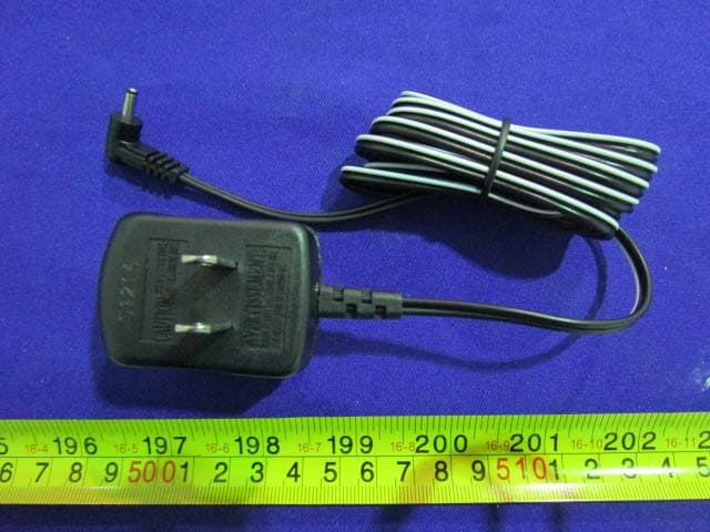
Q9PPCR325W1
Feb 03, 2015Atomic Projection Clock
Equipment Class
CYY - Communications Receiver used w/Pt 15 Transmitter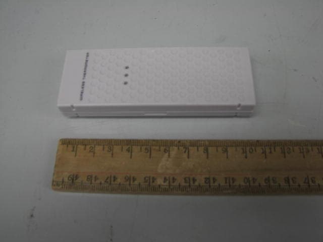
Q9PTS21
Sep 02, 2010Wireless Thermo-Hygrometer and Wireless Thermometer
Equipment Class
DSC - Part 15 Security/Remote Control Transmitter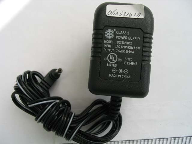
Q9PTE923W-EL-NL
Jul 09, 2006Professional Weather Station with Remote Control
Equipment Class
CRR - Superregenerative Receiver
Q9PTS24C-34C
Jul 09, 2006Thermo-Hygrometer Sensor
Equipment Class
DXX - Part 15 Low Power Communication Device Transmitter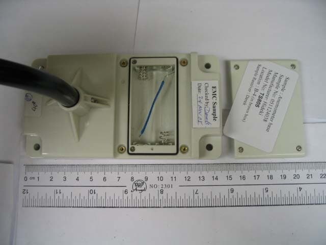
Q9PTS805
Jul 09, 2006Anemometer
Equipment Class
DXX - Part 15 Low Power Communication Device Transmitter